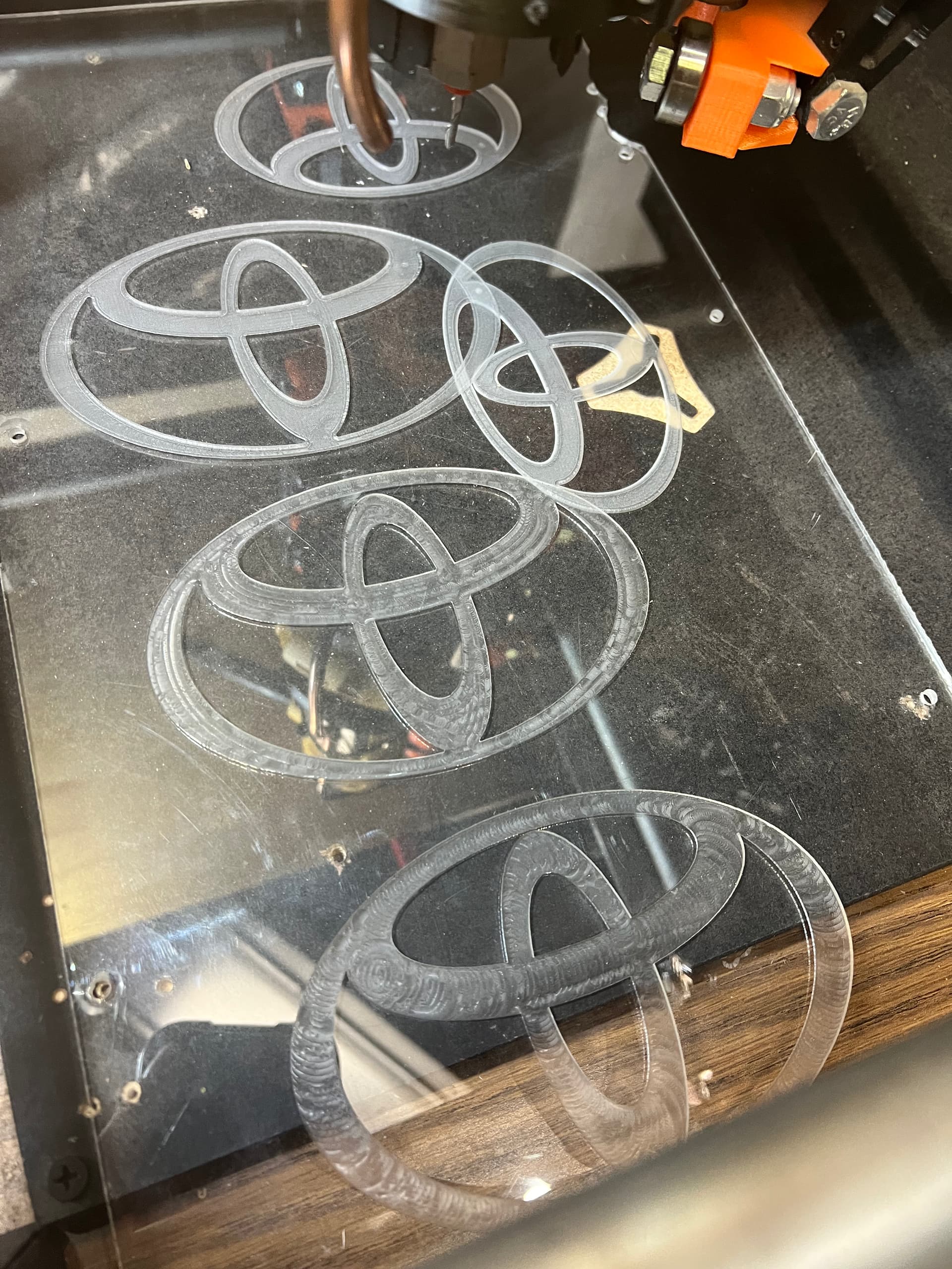
I’m struggling a bit on the learning curve of milling. I’ve successfully made a few test runs with a Toyota logo, experimenting with 2D adaptive, 2D pocket and 2D contour paths into plexiglass, not completely through the stock, to allow to be used for edge lighting.
These paths were generated in fusion and sent from Repetier as well as on sdcard and ran from the mpcnc display.
But now i can not figure my way through its current behavior. I think maybe i have something wrong in my setup but the behavior tells me it must be something else. I’m running flyfishers post processor. Maybe i have something wrong there. It doesn’t seem to repond to X and Y commands until near the end, which appears to be the final 2D contour, but its path doesn’t resemble the created tool path. I’ll link videos shortly.
It’s not very noticeable in the video but at the end of the plunges it does do a little x and y action, which I assume is like a full depth finishing pass on the 1/8” holes with the 3/32 ball nose, but the first 2 plunges are to be a 2D adaptive for the two large holes. I have no idea what is going on.
When I look at your g-code in a simulator, it looks fine, but when I look at the g-code itself, movements are tiny. It looks like you authored your model (CAD) tiny. Typically, this kind of problem occurs because of a mix up in inches/mm, but that does not appear to be the case here. Could you attach/upload a copy of your Fusion 360 file? You will need to put in a ZIP file first.
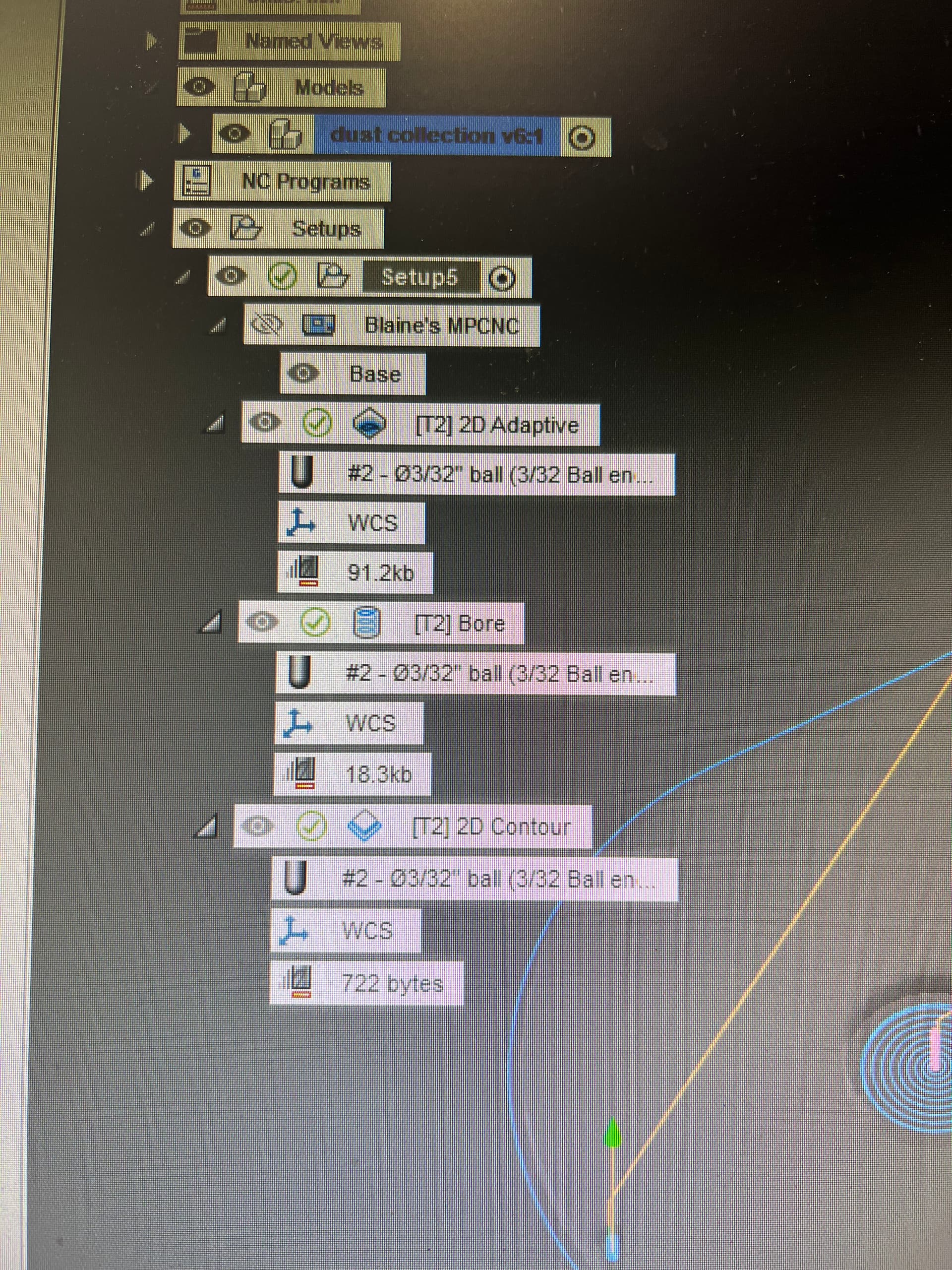
i see the tiny movement, and the J shaped tool path near the end is really confusing to me, instead of an oval pass around the perimeter. The speed seems a bit fast too to me for a 3/32 bit. i had to create the tool profile but i haven’t put time in to editing feeds and speeds yet . The rest of the project has 3D printed fine. just need to use the mpcnc to cut the top and bottom from plexiglass.
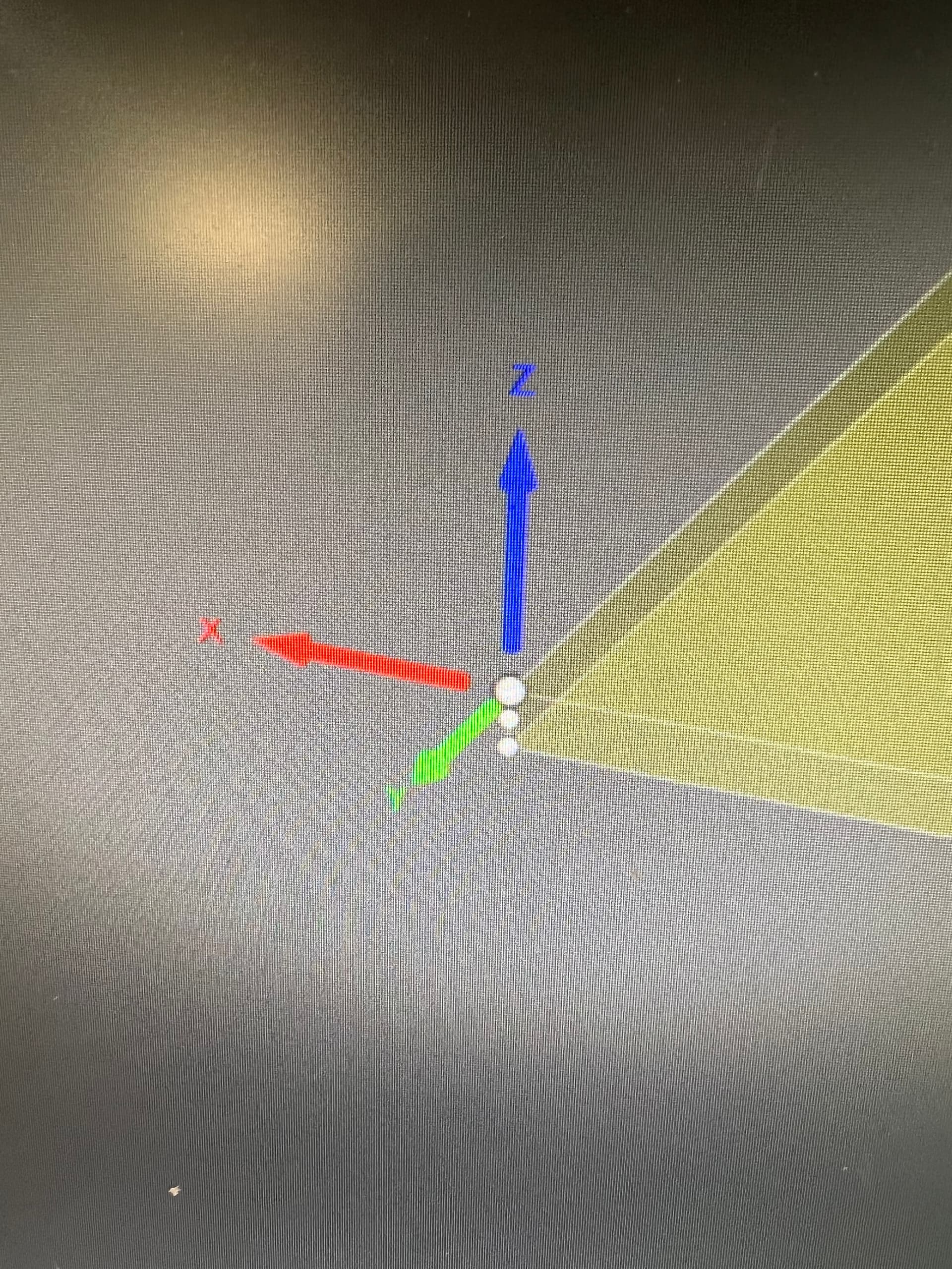
Ok, one issue i see is that the x and y gcodes are negative numbers. It’s as if i missed something in setup to reference the origin of my stock at the bottom left corner, home000.
I was able to push the router out to the middle and start the gcode in Repetier and it does run the file and looks correct, but it is starting at the opposite corner and coming back, which after looking at the gcode, it appears to be doing exactly as it’s written.
How do i create the code that it acknowledges my home position and create all x and y coordinates in + numbers?
I just don’t understand what i’m missing here, since I’ve already created several Toyota logo files that did reference from home position and ran as I wanted.
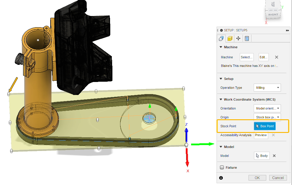
To get your requested result, you want to select “Stock Point” if it is not already selected (orange rectangle), then you want to select one of the points indicated by the orange arrow. If you select the top point, then the top of the stock is your reference. If you select the bottom point, then the spoil board is your reference. Personally, I like to use the spoil board as reference for contour cutting in wood where the measured top (touch plate) may vary in height.
Edit: I was just about to close Fusion 360 when I realized that personally I layout horizontal items along the X axis. This is mostly arbitrary, but it does make the stock easier for me to clamp on the spoil board. So if I was doing your model, I would do the setup this way:
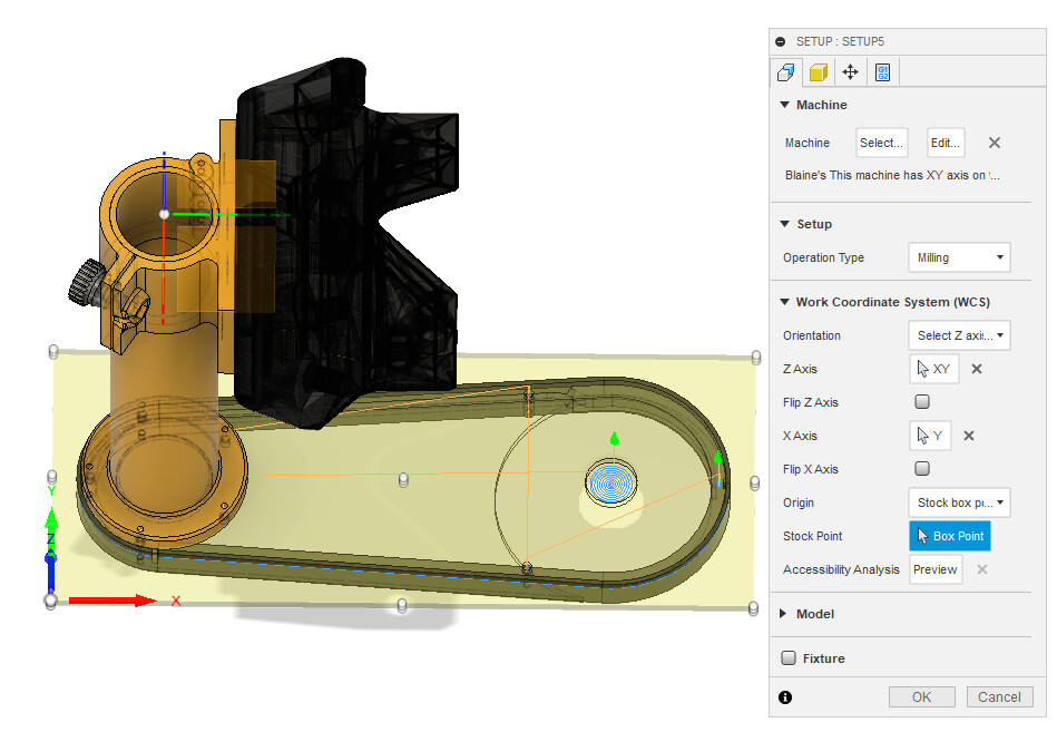
I just figured it out. I feel dumb. I didn’t notice the direction of the x and y arrows at the point i selected on the stock. It was simply a matter of selecting the opposite corner of the stock to get the arrows in the correct direction. Which still doesn’t quite make sense to me. Like why couldn’t i designate the corner that i selected? Oh well. Lots to learn. Just wish i would have figured it out 2 days ago. It fits nicely in the printed part.
There are all sorts of different ways you can establish the coordinate system for your stock, but the corner you selected will not work unless you flip your stock. Fusion 360 uses what is sometimes referred to as a left-hand coordinate system, and, from the corner you selected, you cannot get a positive X and Y. You could use the back right corner.