Well, with a downcut bit, the cutting force is downwards, which does make for a nicer topside finish to your piece, since there’s less tear-out. But, it pushes all the wood chips down as well, which can cause problems, especially when you’re cutting a slot (even more if you’re just plunging a hole the same diameter as your bit).
1 Like
I found as a result of a slightly out of flat tube my router wasn’t perpendicular to the cutting surface which gave me slight off-square cut edges. This is visually pretty apparent but worth mentioning.
The feed rates and doc is always an issue. If you’re having issues like this go back to really slow and really shallow until the problems go away. Most people here I think are using 1/8" bits for most cut-through operations. I’ve tried the 1/4" bits and for the benefits of longer reach and not being able to break bits, needing to cut more wood, and needing to slow the feed rates as a result didnt give me any gains in time.
For an idea my machines have cut pretty happily around 4-5mm doc at between 8-10mm/s. I’m using a 4ft wide axis for my tubes.
Sorry for the delay but work has been busy this week.
Took all advice on board.
Tightened up the belts. They are all much tighter now.
Slowed the 6.4mm spiral bit down to 300mm/min but cut 4.5mm deep
Flipped the Estlecam file around by 90 deg
Had another go.
Came out much better.
So on that one.
A. length is spot on
B. width is still a bit narrow? 29.41 vs 30mm
C. holes are a bit oval but much better.
D. 30mm width is correct
E. 20.2mm wide is pretty close to 20mm
F… 29.1 vs 30 which is a bit narrow.

So it is wandering around a bit really isn’t it?
Then.
Redid the gcode for 3.2mm standard bit.
A. drilled the holes, ie not pocketed for first 2. seems to have caught an edge on hole 2, First one is fine.
B next 3 holes were pocketed out. Look pretty good. But not perfect (here is where I am wondering if I am asking more of the machine than it is capable of?)
C.width is 29.6mm vs 30mm
D.width is 19.8mm vs 20mm
E. width is 29.1 vs 30mm
F. last cut on this face shows a ridge along the bottom so it has wandered a bit. 19.8 vs 19.9mm (getting nit picking aren’t i?)
G but here the grain of the cut looks totally different but I guess that is the nature of going with the grain vs against the grain?

So in closing, I reckon you were right to suggest too fast for the cutter size etc and belts too slack.
But my key question is … How accurate a result should I be looking for on these small dimensions, ie machine is 2.4m long and I am cutting 20 mm bits.
I am not unhappy just curious.
There has never been a “spec” for it. I would consider something under 0.5mm without a finishing pass pretty good, and I would expect 0.2mm or so to be acceptable, but with some more room for improvement if you have a finishing pass. This is just based on my gut, not from any kind of analysis.
But, wood is a natural material, and there is also some stretch in the machine and the belts, so for the money, and effort, 0.2mm over a 2.4m span seems pretty freaking good.
We have seen some exceptional results from some users. Down to smaller accuracies, but every machine is different. And I can’t remember if those higher accuracies were on smaller machines, or mpcncs or what.
Glad you got it working better, and you’re happy with it.
1 Like
Happy with it… ??? I am really happy with it.
This is the most fun I’ve had for a while. I just love the whole ‘robiticacality’ of it all. Designing in F360 and then cutting then putting together then using… It is a totally immersive thing that we have here.
Takes your mind of viruses for sure.
Any lurkers out there, get one.
R
2 Likes
I agree. I love my lowrider. It has enabled me to make things I would never have tried otherwise, however…
When I’m actually watching the CNC work, I feel a little bit like I’ve turned wood working into a spectator sport…8^)
It feels a little bit like I’m cheating too. ![]()
Well, just re-did it in Estlcam with a finishing cut, never done that before, and it has come out perfectly.
Think I finally have it under control.
Got the micrometer out and it seems to me that the biggest error I can find is in the Y axis and is 0.02mm.
I think that is “good enough” on a machine that can cut 2,400mm in the Y direction. ie 0.02mm across a 30mm wide object in pine. I am no engineer but I reckon that is astonishingly good. It is amazing to my untrained mind.
Rainy good Friday here so more shed time to come.
Designed up a ply shelf with a tab in fence to stop vaccines falling down the back of our vaccine fridge at work so that is next to come.
Thanks again you blokes.
Rob
3 Likes
Very neat.
I love watching it move around too. I secretly reduce the maximum acceleration lower than it needs to be so it has to smoothly start and stop. I love how smart it makes it look. I have been fooled though. It is definitely stupid. It will do exactly what I told it to do.
1 Like
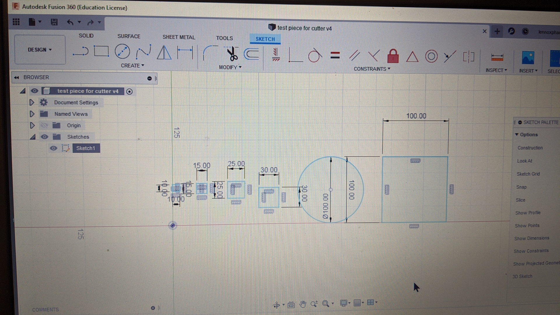
Well. Was thinking more about this so did up another piece in FS 360.
Took it into Estlcam

Then cut it out of some 12mm ply.
Consistent error across the X axis of about 3mm

So here is my looking at it.
The X axis error is pretty much 3mm too small right across the board,
10mm sq is 7x9.6
15mm sq is 12.4 x 14.8
25mm sq is 22.3x24.5
30mm sq is 27x30
100mm sq is 97x100
100mm circle is 97x 100 with X always shorter.
This is not a % error, it is consistent across all sizes.
What have I done wrong? Is there something in the CNC setup in Estlcam that could be doing this?
Puzzled.
Check your start up routine did you zero correctly?
Well.
Dunno as they say.
I screwed wood to table
Moved the router to the xyz kick off point.
Used the reset all command, it beeps and that is the xyz point and then print.
Am I missing something?
R
Sorry no you are not . Maybe @jeffeb3 or @kvcummins will have a idea. I dont.knkw what can make 1 axis different than the others
I don’t get it. I thought we had solved it already.
The estlcam toolpaths look a little funky to me. Like they are engraves on top of the lines. The bit is about 3mm, right? Can you post the gcode? We can probably look at the dimension on one of the squares and see if it is full sized.
Won’t let me upload a gcode?
Ok, just did a 100mm square again on it’s own.
New gcode
Did it one way.
Then went back to Estlecam and rotated it through 90 deg
No finishing cut
Both 97x100mm
ie the X axis is always short by 3mm
Here is the Gcode for both of them plus the original one as well in one folder.
Stuffed if I know.
Thanks
R
https://drive.google.com/drive/folders/1T_SCOUJ_q8eoYvXdJj4Z3WF-Lcan6bwx?usp=sharing
Could it be short one diam of the cutting tool? ie 3.2mm? Is there some thing in the setup that starts it on the wrong side of the xyz zero point?
;No. 3: Hole 3
G00 X49.9640 Y26.1850 Z4.0000 F2100
G00 Z0.5000 F480
G01 Z-3.0000 F300
G01 X43.6390 F600
G01 Y45.0100 F600
G01 X49.9640 F600
G00 Z0.0000 F480
G01 X56.1390 F600
G01 Z-3.0000 F300
G01 X62.4640 F600
G01 Y26.1850 F600
G01 X56.1390 F600
G00 Z0.0000 F480
G01 X49.9640 F600
G00 Z-2.5000 F480
G01 Z-6.0000 F300
G01 X43.6390 F600
G01 Y45.0100 F600
G01 X49.9640 F600
G00 Z0.0000 F480
This is from one of the square holes on test 2.gcode. It is a little hard to see, but Y goes to 26.1850, then Z, X move around and Y goes to 45.0100.
So the Y length of this side is 45.01-26.1850=18.825. If you subtract 1/8", it is 15.65. Shouldn’t that be 15mm exactly?
The X also goes from 43.6390 to 62.464, which is also 18.825. So that doesn’t explain why it is different in X.
So, after looking at the gcode. I think it looks fishy, but it doesn’t explain that descrepency.
What does the machine look like when you send a 3mm move in X? Try switching directions. I am wondering if there is something loose (like a pulley) that is causing 3mm of backlash. 3mm seems like a lot for that though.
Have you done anything to adjust the steps/mm in either direction?
So what happened since here? I am confused how the error jumped 3mm.
does your machine have duel end stops? if so the x and y cuts start in negative space but that only explained that instance
1 Like
Will try that manual move of the machine with the router going across a bit of ply in a few hours when the sun comes up.
The accuracy I was talking about was in the Y axis and to be honest not sure now of the X axis measurement as it was longer than the micrometer so probably did not measure that dimension. I would have assumed it to be as accurate as the other.
I don’t know how to adjust steps/mm so if I have it would be accidental.
I did pull it apart and put new Y plates on with fibreglass and epoxy on them to stiffen them. I will remeasure some of my old work (before rebuilding) and see what it is like to the mm and report back.
Will do all that when everyone else wakes up.
R
1 Like