Merry Christmas everyone!!
Is there any plans around for a full size table?
Thanks
Merry Christmas everyone!!
Is there any plans around for a full size table?
Thanks
I just finished my full sized table. I don’t have any plans for it but I can take pics and post them if you want. I just kinda winged it. Made out of 2x4” for the most part with SuperStrut for the Y-Axis rails.
That would be awesome mate. Pictures would be much appreciated. Thank you
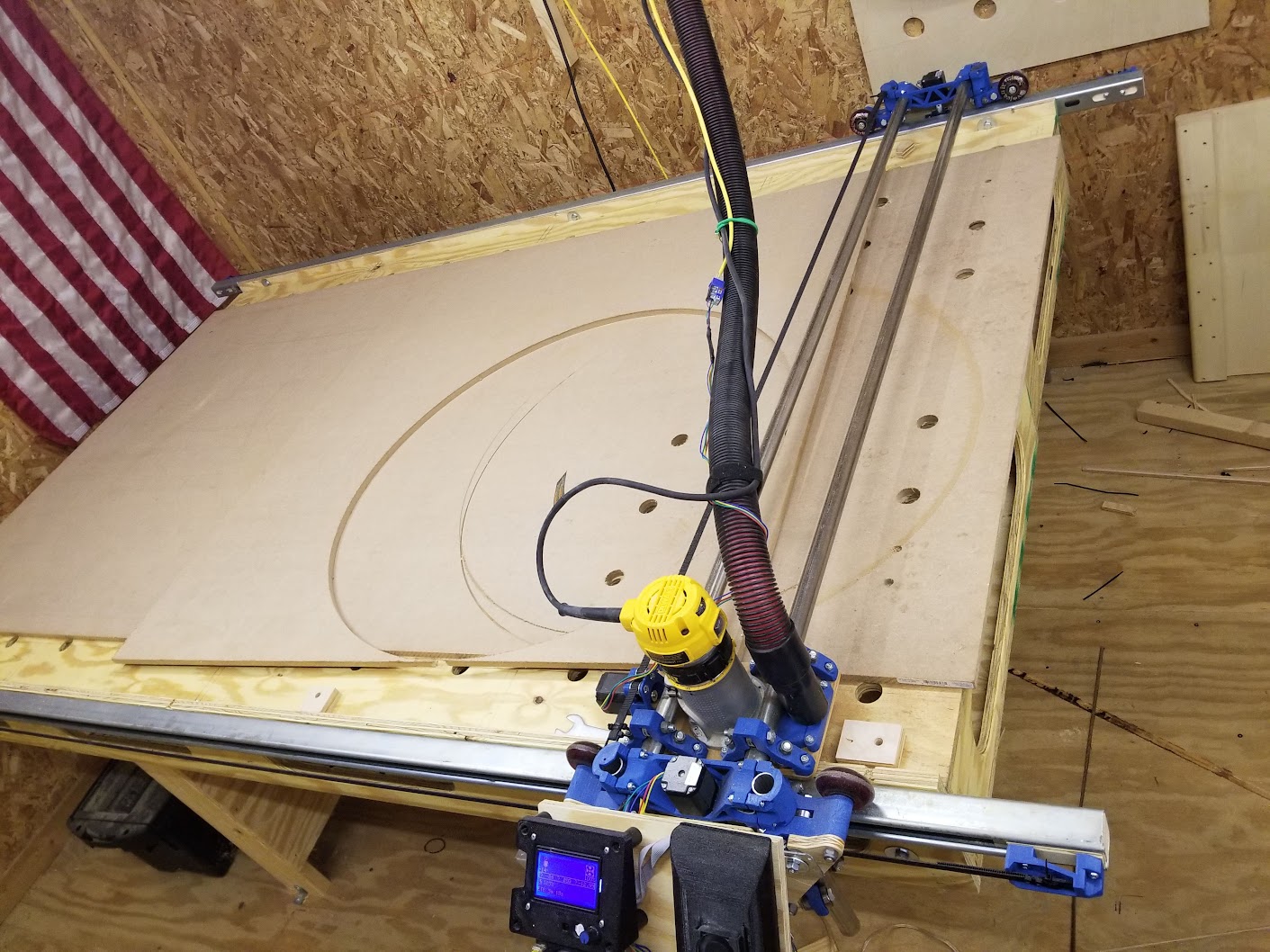
Here are a bunch of pics I just took. It’s a bit messy right now as I was using it this morning.
It’s a full sheet table so the overall dimensions are 56" wide by 111" long. For the side rails I based them off of Jeb’s build (https://www.v1engineering.com/forum/topic/jebs-lowrider-v2-build/) - using Unistrut (which comes in 10’ sections so I just left them full length. This way they hang over the end of the table and give me room to play with so I can move the LR2 out beyond the table. I can then get underneath the router and change the bit without having to remove the router from the 611 Plate.
The rest of the table is 2x4 construction with the legs and the 4 sides all being doubled up. Once I had the basic 2x4 top made and before I put in any of the cross bracing, I squared the entire table up on the diagonal to within 1/64th of an inch. Once I had it square, I clamped it down to my work table and put in the cross bracing, putting the 2x4 cross bracing at 16" on center. I then ran more 2x4’s down the middle of the table lengthwise to add more rigidity. This kept the entire table completely square.
After the table top was finished (all the 2x4’s and cross braces in place, I then flipped it upside down to install the legs. I did this because I figured the “bottom” (before I flipped it over) would be flatter then the top since I was building it on a flat table and the 2x4’s were resting on the table. I used metal corner braces to hold the legs in place until I could add the diagonal supports (which is what I used to keep them stable and also to square them up). I then attached casters to the table so I could easily move it since I keep it in my garage and need to move it around when I want to use it.
I then made a router jib for my full sized router and used a facing bit to face it down about 1/2" off the top of the 2x4’s to help get rid of any inconsistency’s in the 2x4’s and my ability to get them level. I know this isn’t exact and not sure it helped at all but it’s what I did. I also did it because I made an error in the design and if I didn’t do that, the MDF top of the table would be sitting higher then the Unistrut was. I know now that this isn’t a big deal but at the time I wasn’t sure. After I routed out a 4x8 section, I then dropped in a 3/4"x4’x8’ piece of MDF into this routed slot. I then screwed this MDF down to the 2x4’s in each corner to help hold it in place.
In putting on the Unistrut, I couldn’t use the holes it comes with so I just drilled new ones in-between those slots. This let me raise up the Unistrut by about 1/4" which also helped to compensate from my design mistake. I used another small piece of MDF as a guide to install the Unistrut by laying it on top of the table and lifting the Unistrut up to the bottom of this additional piece of MDF (which I just clamped down while doing this). This let me get the Unistrut as level as I could (but I still got one side about 1-2mm to low (I know I’m mixing SAE and Metric here but I tend to think in SAE for large measurements and Metric for small ones - I really wish the USA would switch over already!!).
That’s pretty much it for the table itself. Instead of using a piece of Aluminum angle iron for the wire guide, I used a piece of 1/2" diameter conduit that I had lying around. I was able to fish the wires through this and it works great so far. You can see it in the pics. I also have another piece clamped to the end of the table to act as a wire holder. My plan is to screw this down to the table, add another one to the opposite end, run a piece between them and then hang the wires and vacuum hose from this conduit using shower curtain rings. This should hold the wires up off the table and still let them freely move as they need to.
Another thing I am going to add if from Jeffeb3’s table - a 1" or so strip that runs the length of the table that will help guide the wheels and will also help keep the dust level in the wheels and lead screw down. Right now, they are getting covered in routing dust. I also plan on placing a thin sheet of plexiglass coming off of the XZ Main that will hang between the Unistrut and the lead screw to act in the same manner.
That’s all I can think of for now. If you have any other questions, just let me know.
That is one heck of a beefy table!
Yeah, in reading all your thoughts on it, I realized heavy and sturdy is best… lol.
Jeff that is a beast. That would be what? 30-40m of 2 x 4? I really like the way you’ve braced it.
So the spoilboard is supposed to be flush with the unistrut? and the only thing sticking up would be the workpiece? IN my case mostly 16mm MDF
After using it for a while, I don’t think it’s critical that the spoil board be flush with the Unistrut. If it isn’t, you will just loose that same amount of Z travel. A bigger concern, is getting the unistrut to be as level as possible to the spoil board and to have them at the same height. I’m thinking of making a jig and reattaching mine just to dial in that extra little bit of accuracy.
As for 2x4’s, I used 4@10’ and (if I remember correctly) 8@8’. I also scrounged some smaller sections from the work table I replaced this with. If I had to guess, I would say I used 12@8’ all together, which is just over 41 meters (so, damn good guess on your part!).
I have the 3/4” mdf as the top of the table and I put another layer of 1/4” Luan on top of that for a spoil board. I used 4 sheets of Luan 2’x4’ each so I could replace just sections of them that needed it instead of having to replace a single 4’x8’ sheet. I haven’t actually attached it all yet, just the 1 piece where I have been working.
I’m surprised myself with my flukeass educated guess.
Hey thanks heaps for all the info. I really appreciate it
Yeah, if you just put a router on a gantry and then added some motors, you could get it really flat ![]()
OMG! Lol! Too damn funny. I guess one or the other idea would do the same thing - dial in the table to the Unistrut or dial in the Unistrut to the table…
I actually hadn’t considered that the two things are achieving the same purpose until you said that… must be the food coma taking over! Lol.
So I was just thinking. My table length according to the JSCalc needs to be 2821mm. A full sheet of MDF is around 2440 long. So this would mean that If I’m going to put a sheet of MDF ontop of the table, I would have to add a piece of around 400mm to the end?? I may not be thinking straight here, but wouldn’t that create a ‘bump’ when the wheels are going over that join? Or would you need to putty fill any gaps and sand smooth?
My table top is a full sheet of plywood long. The mdf spoil board hangs out an inch or so on either end. The unistrut rails stick out 6 inches on either end, since they’re 9 feet long. If anything is going to be unsupported, it’s only going to be a couple inches, so I don’t worry about it.
If you look at the second pic I posted, you can see where the full MDF sheet ends and how the structure of the table and the unistrut extends beyond that. You need to go bigger then what you want your actual work area to be to give the machine room to get the router bit to the very edge.
There are 9’x5’ mdf sheets made, fwiw. I doubt the seam will make that much difference.
I totally agree with this. I was worried about seems and such which is why I went the Unistrut route, it after using my LR and having it Run Over some of my stepper motor cables, I can say that I doubt a seam would be an issue! Even with running over the cables, I didn’t notice any problem with the piece I was cutting. With that being said, I spent about 3 hours today doing cable maintenance on my machine. I will post pics tomorrow when it is done.
My progress so far. As you’ll see in the pics I have made the table quite a bit bigger than the calculator said. I’m really happy about the comment on the seams not making any difference. Obviously they will be screwed down and levelled pretty much spot on with the main piece.
I’m thinking, sand down the two long edges so they’re smooth, and have the wheels ride on that. Will 35mm be enough width for the wheel to ride on?
Secondly I’ll centre the full sheet of 16mm (or closer to one edge) and bolt it down. To cover the remaining part of the table (minus the 2 x long 90x35), I was thinking of using 18mm MDF to surround the 16mm, leaving a 2mm pocket for the full 16mm MDF workpiece to sit into. Does that make sense?
Anyway, your thoughts and criticism.
PS. Squareness in the X direction (so far) is right down to the mm. I think the other way I’m out by 1 to 2mm max.
Looking good! Great big shop.
If you are using the outside wood for rails, there was an idea I suggested to someone else that I think would be awesome.
The MDF will be really close to trammed with the gantry that way. You have cnc experience, but if you were worried about your first job being a surface operation, you could always just clamp a spoil board right now and get to testing.
Not a bad idea @Jeffeb3 . So you mean just let it surface the whole area it can reach, meaning all the cross (X DIR) sections, and then sit the 16mm 8x4 inside that, recessed at say…5mm??