From Novice to Slightly above Novice: My Lowrider v3 Build Experience

I want to start by expressing my gratitude to V1 Engineering for their Lowrider v3 CNC router kit. It’s a game-changer for someone like me, providing an affordable yet full sheet-capable CNC router kit. As a beginner in this field, I acknowledge my limited knowledge, so my observations and suggestions are just reflections of my personal experience.

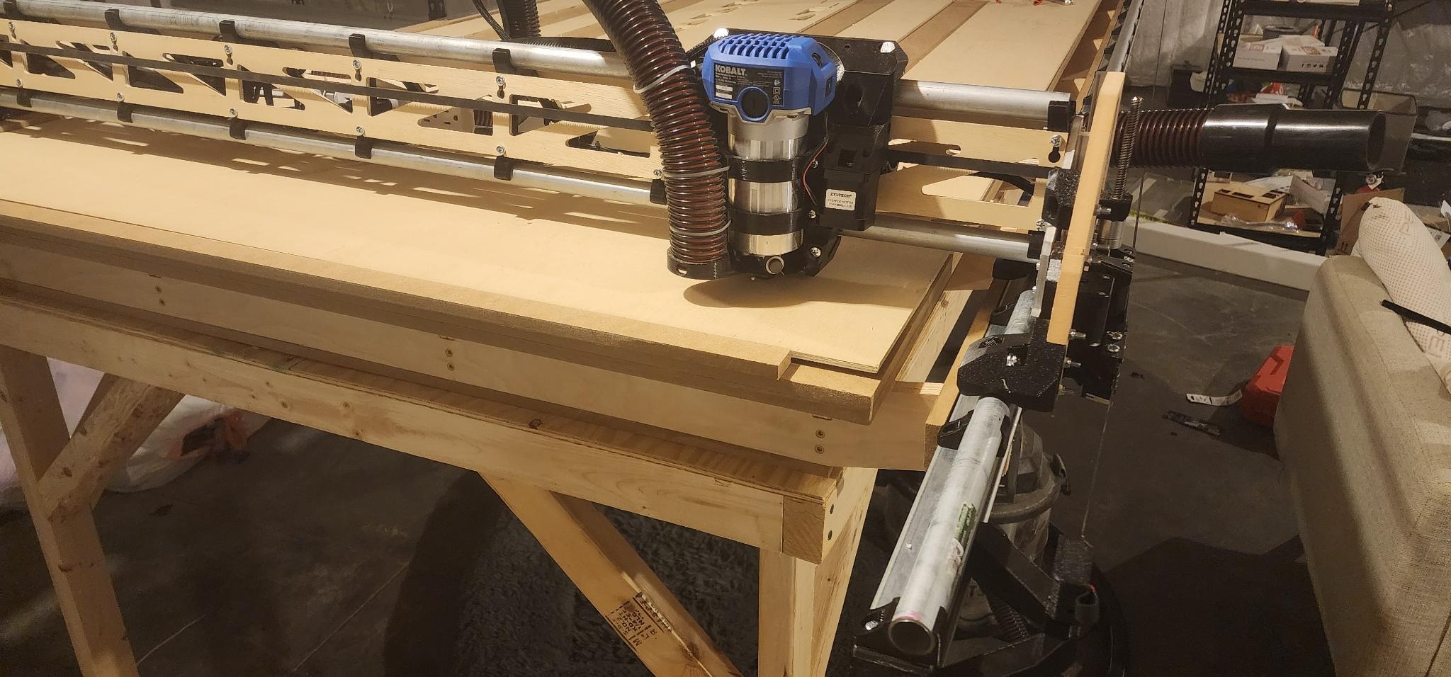
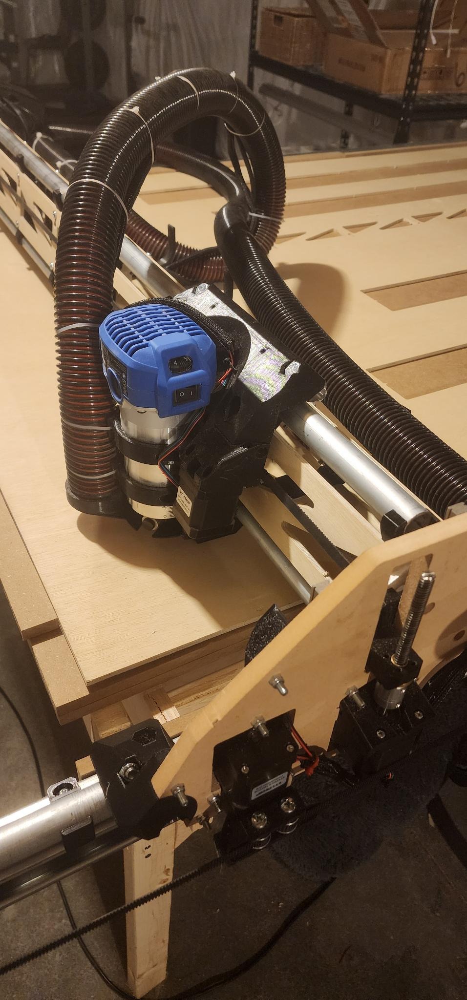
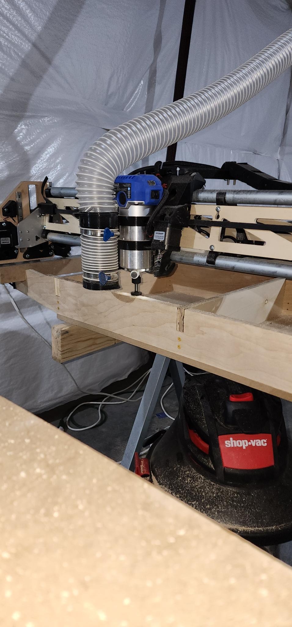
My primary objective with this machine is to create cabinetry from plywood of various thicknesses (3/4in, 1/2in, 1/4in). I invested in the full hardware kit, the jackpot control board, all the 3D printed parts, metal XZ plates, 3/4in EMT rails, and precut YZ plates. A valuable addition to the hardware kit would be a touch plate and a set of bits. For the router, I used the Kobalt 1.25hp variable speed.

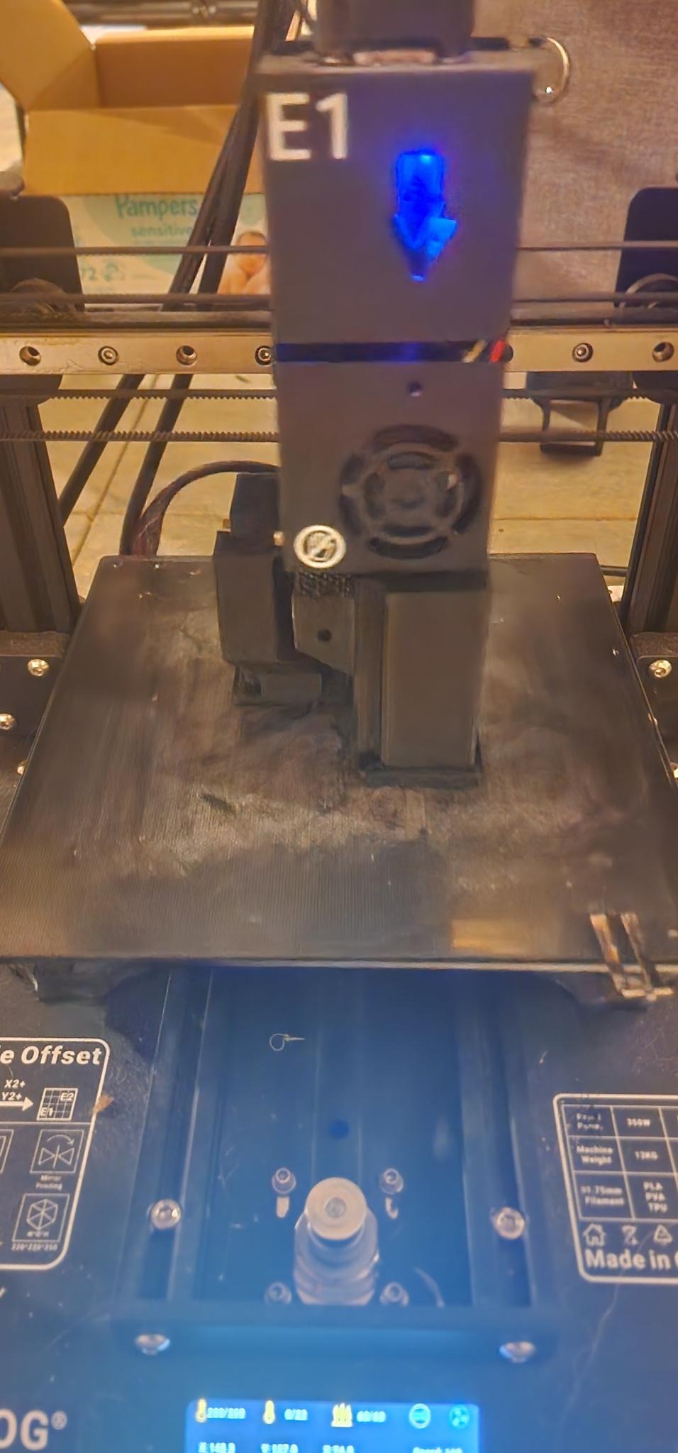
Owning two 3D printers, I initially considered printing the parts myself but later decided that purchasing pre-printed parts was more economical and time-efficient.

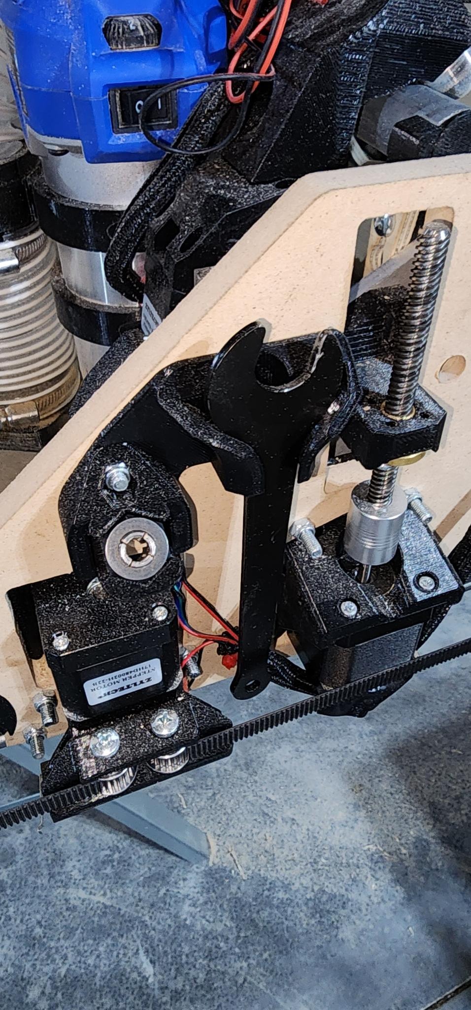
The assembly process was mostly smooth, with a few challenges. Aligning the linear bearings was tricky, but I managed it by adjusting the screws in the YZ plates carefully and using silicone lube. I encountered connectivity issues with the end-stop connectors, likely due to my installation, and resolved this by soldering the connections. There was a minor issue with the Z1 connector on the jackpot board, but it was quickly fixed with a replacement.

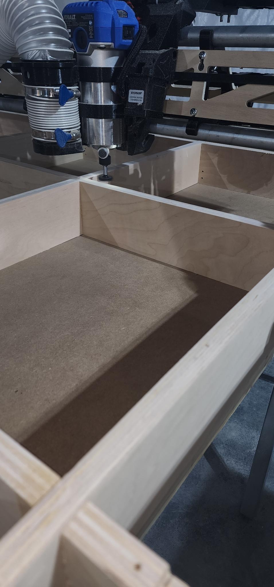
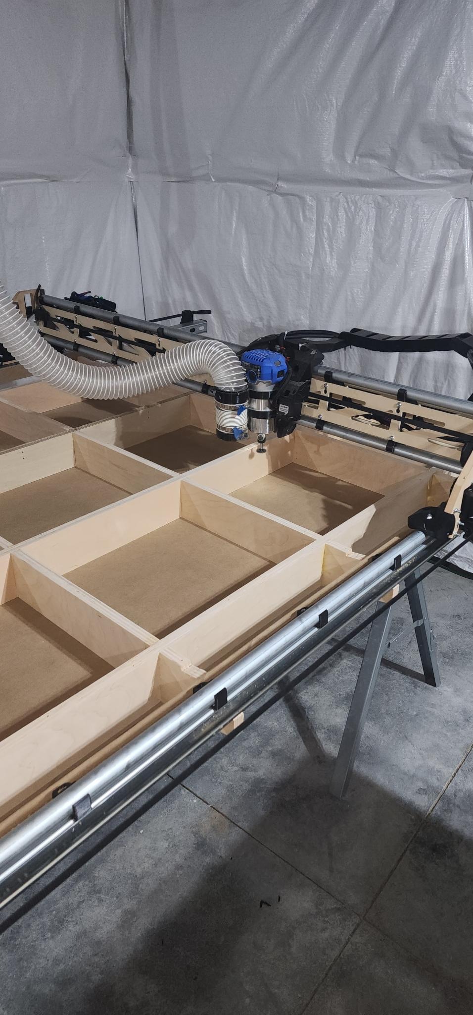
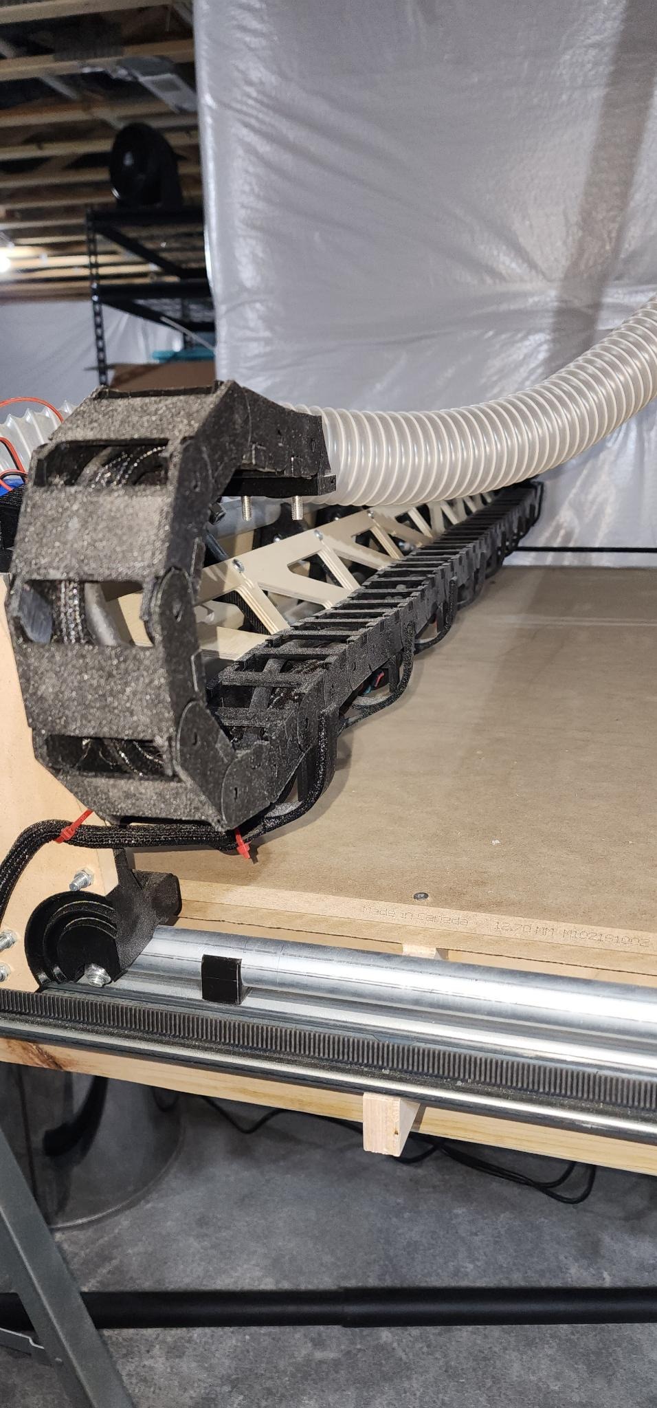
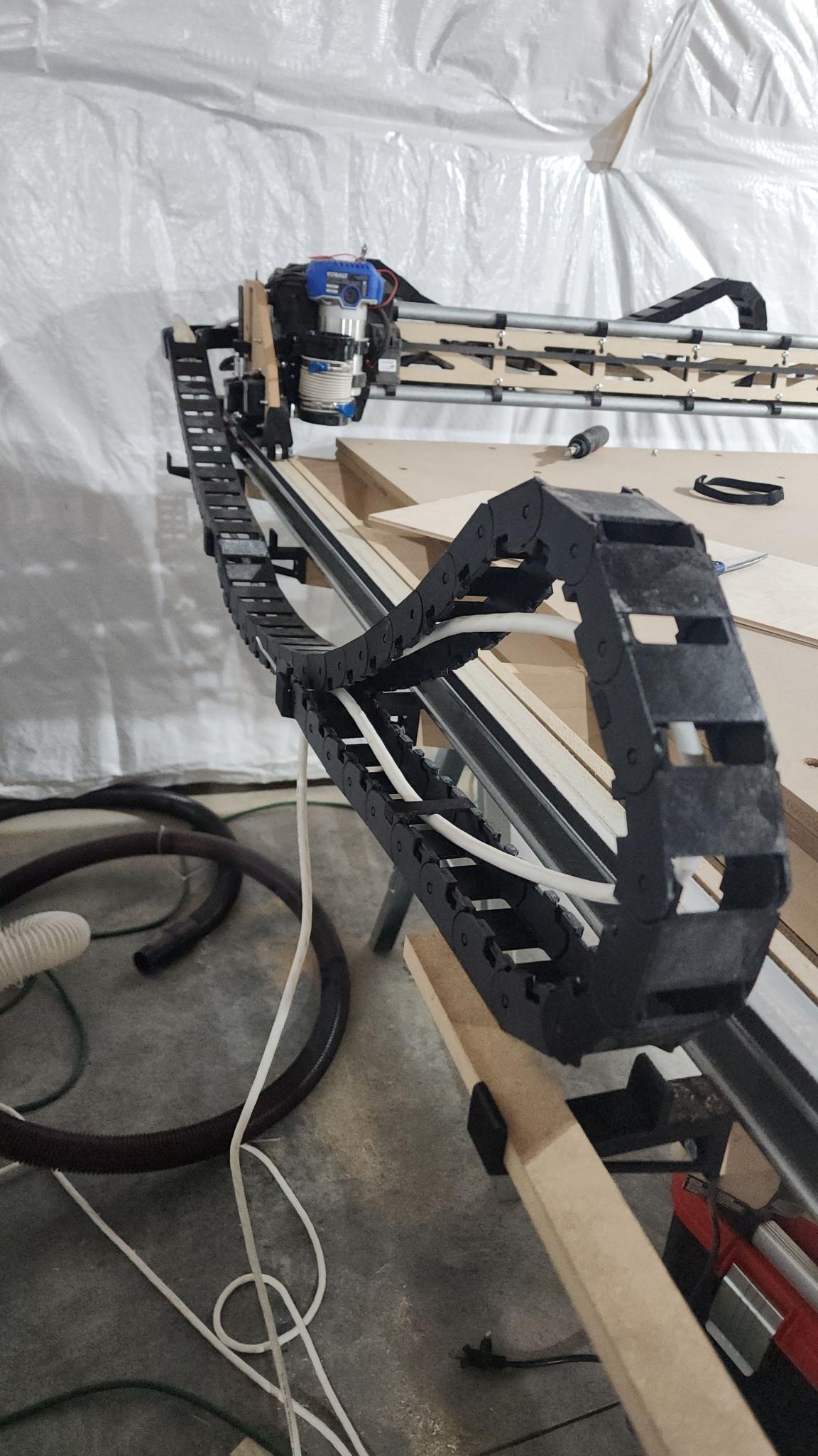
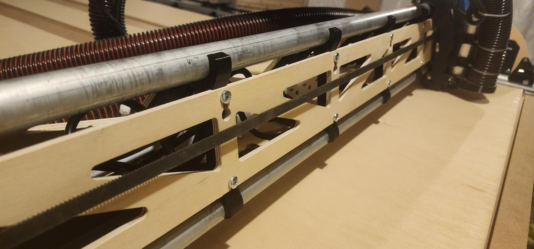
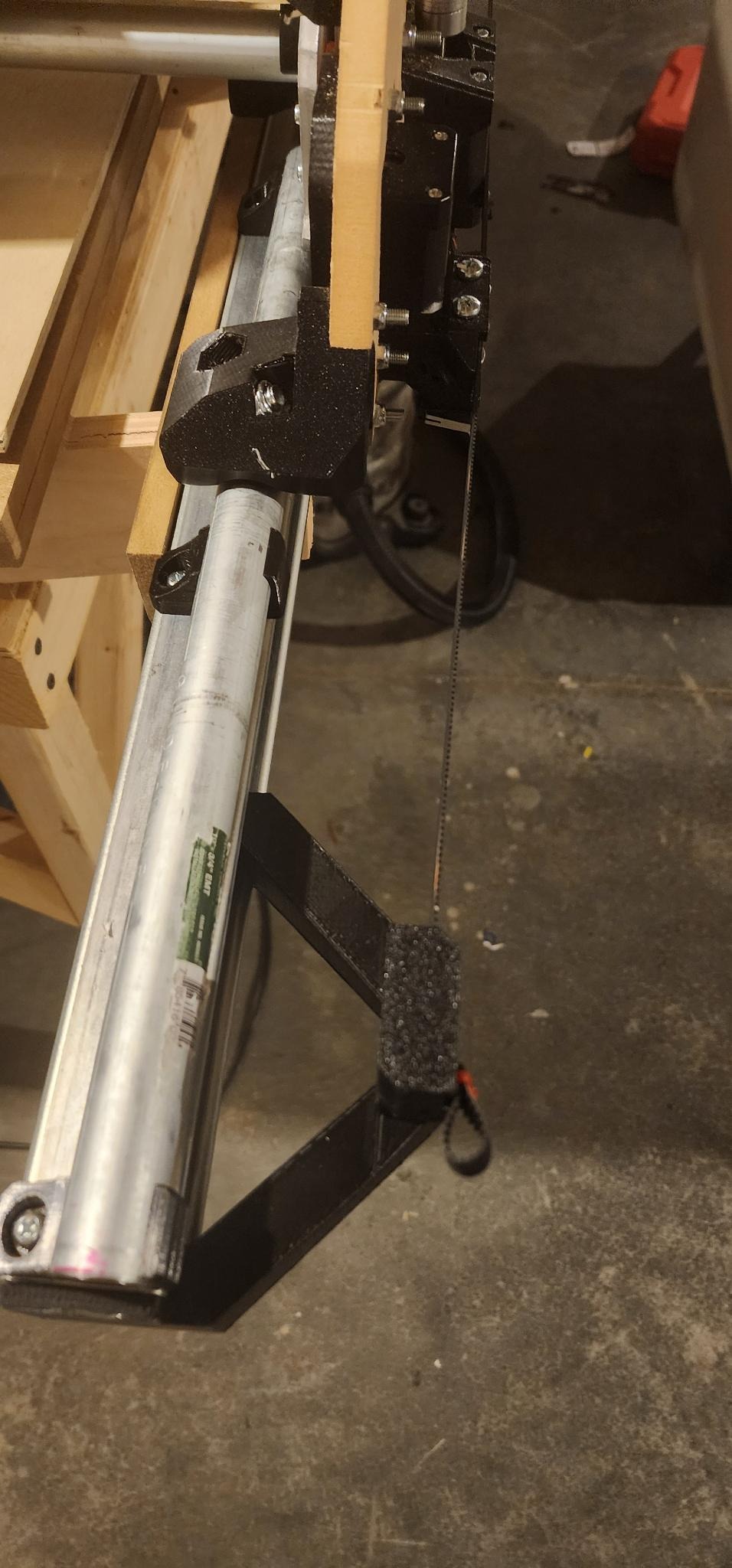
One of my projects was building Doug’s parametric table with metal uni-strut rails. The initial cuts and movement of the Lowrider on the floor for the strut braces were thrilling. Assembling the struts onto the gantry was a bit tedious due to the positioning of the nuts, but it got easier with practice.

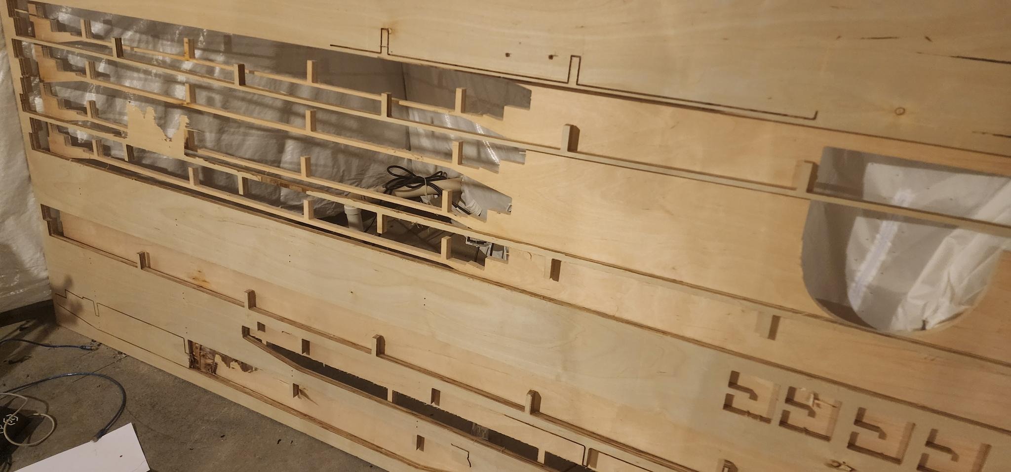
I faced a hiccup with the DXF file for the strut braces, which included an extra gantry brace not in my kit. I 3D printed this missing piece and installed it. Cutting the 3/4in plywood took some trial and error – I used up two and a half sheets due to the learning curve.

For the parametric table, I relied heavily on the Bootstrapping parametric table post. Determining the correct parameters for a snug fit was challenging. I wish the design included a test DXF file linked to the parameters for trial and error. I ended up creating my test fits to figure out the needed parameters.

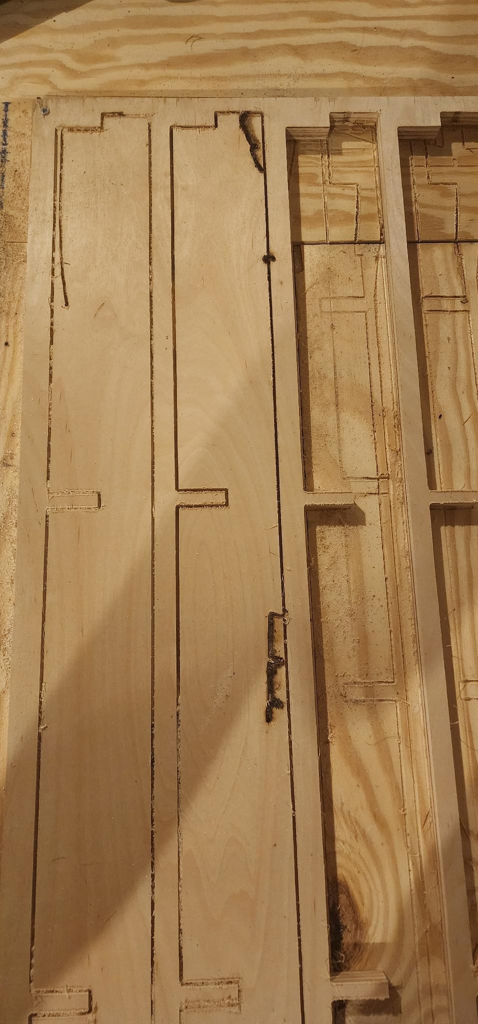
Getting the right speeds and feeds for the machine was a learning process, leading to issues like skipped steps and burnt wood. In hindsight, more test cuts would have been beneficial. Some benchmark files for beginners would be a great addition.

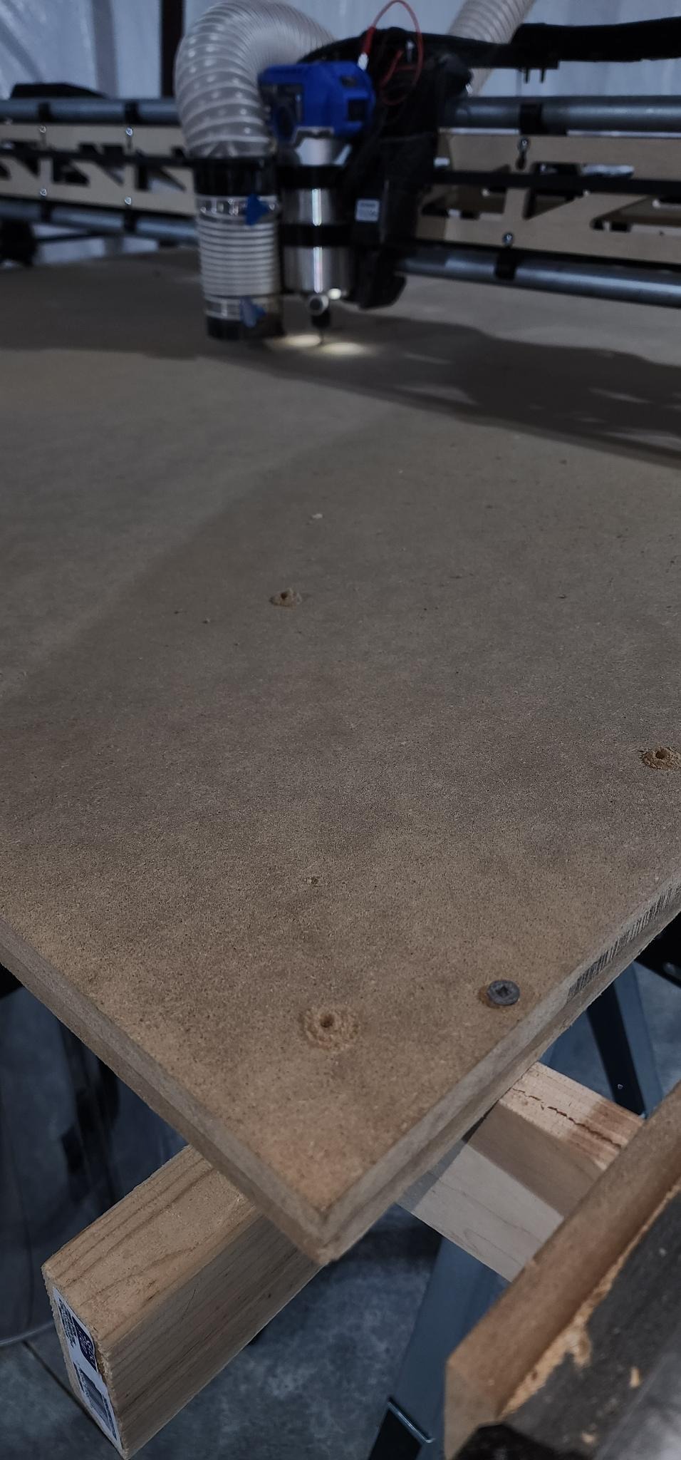
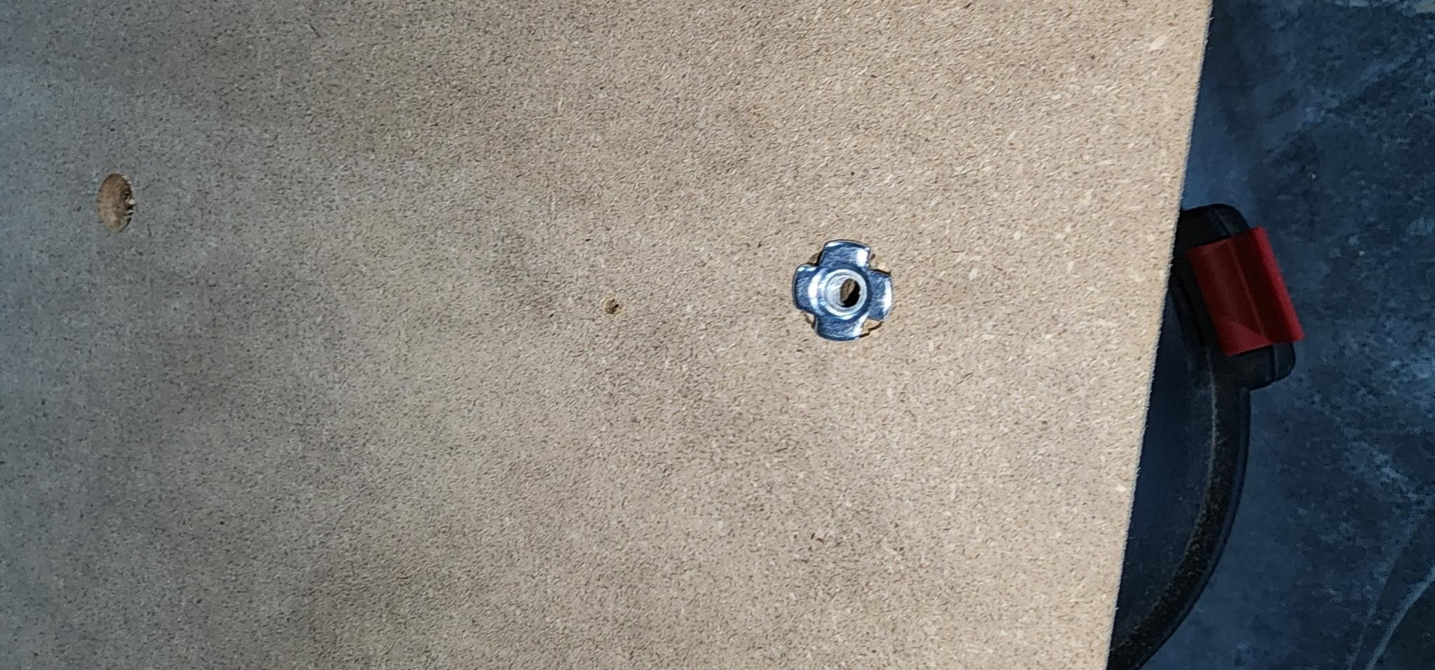
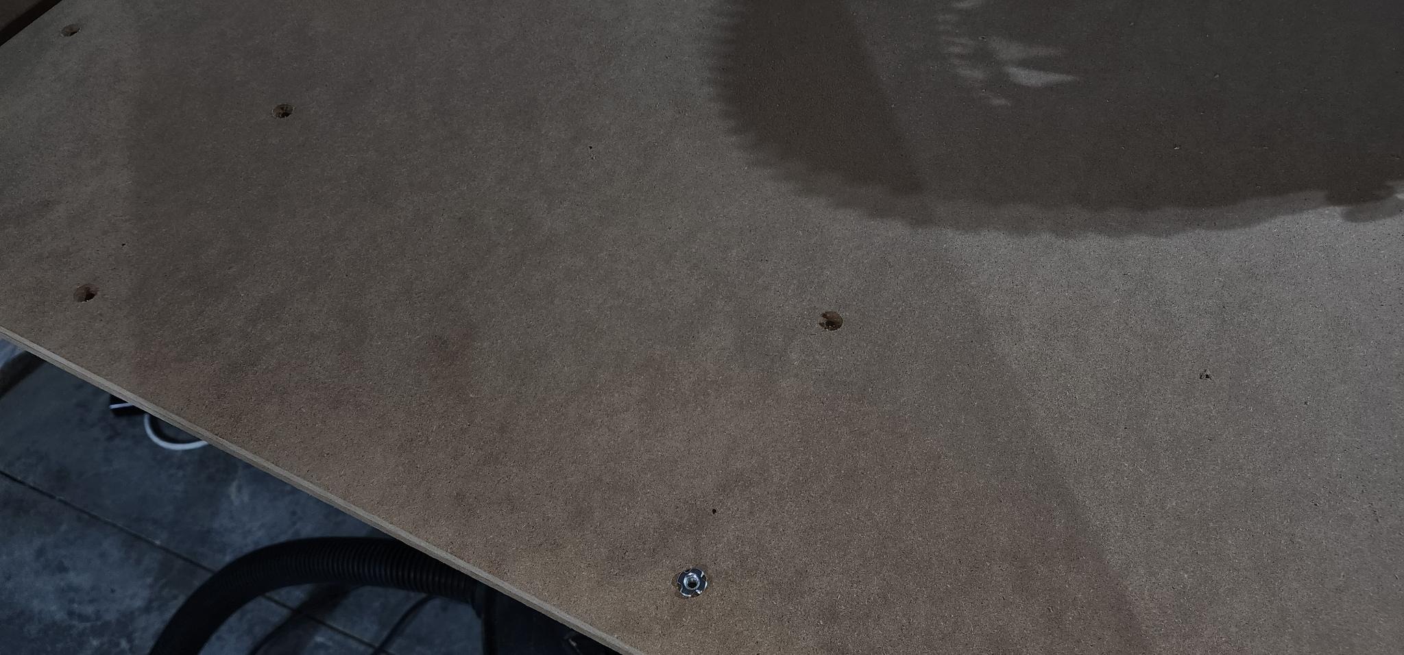
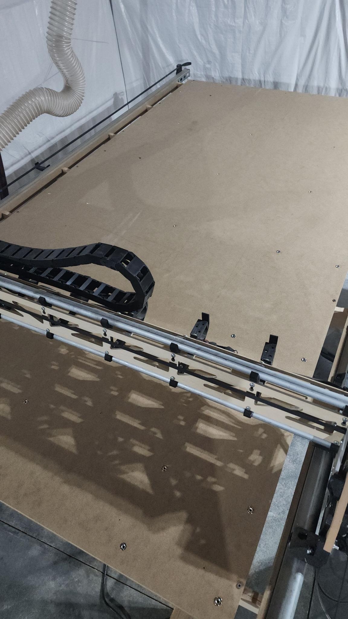
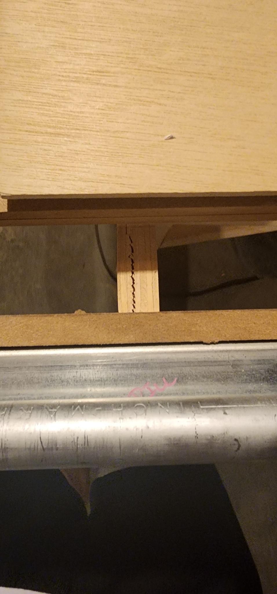
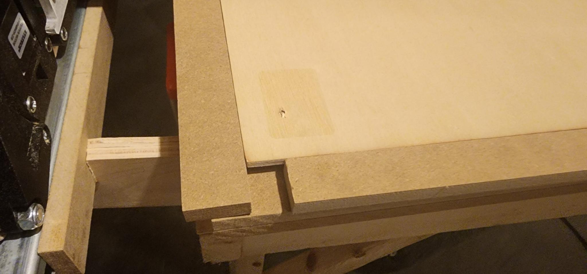
The third plywood panel was successfully cut and assembled into the table, glued and screwed together. I cut the MDF panel to size, using leftover strips as backboards. Cutting the uni-strut to size and attaching it to the x-spars was straightforward, although I faced some splitting in the x-spars despite pre-drilling.

I’m currently 3D printing extenders for the uni-strut. Future plans include adding a reference fence and low-profile clamps for securing plywood sheets.

Building and using the Lowrider v3 has been a mix of excitement, frustration, and learning. Despite the challenges, I’d definitely recommend this machine and would undertake this project again.

10 Likes

Good job with your build!
I’m sure many of us would be interested to see the cabinetry that you produce with it.

4 Likes

You’re doing yourself a lot of favors here. That is a good project to learn a lot and prepare yourself for cabinets. It definitely requires an operator. And it can be frustrating to learn enough to become that operator. It looks like you’re on the right track.

Share anytime. This kind of stuff is always motivating for the whole community (and especially @Ryan).

5 Likes

Reach out in the future, I am sure someone can look at the first panel and see what is wrong and help so that you do not have to go through so much expensive plywood!

1 Like

Great looking build!!! I have built a few cabinets with my full sheet machine and several drawers. I’m defiantly excited to see what you come up with and how you do it! Always looking to learn myself! Any questions you have always post up and ask. Great group of people here always willing to lend a hand to help in any way!!!

2 Likes

Been busy adding some upgrades.

I noticed when surfacing the spoilboard there were some low spots. I deciding to surface the torsion box itself and then attach the top and bottom spoilboards.

I didn’t like the idea of drilling with screws it the same locations to clamp down the top spoilboard so I’m putting some lock nuts on the bottom of the bottom spoilboard and the top spoilboard can be clamped to the bottom using these lock nuts with bolts.

Some additional upgrades include the tool holder, x gantry chain, dust shoe from design8studio. Add the pendant from fluidnc.

The probe wire from v1 was too short for the new x gantry chain so I had to make a new wire.

Next up is a new table instead of saw horses.

3 Likes

All lock nuts installed. Ready to be flipped.

1 Like

Nice! I had this idea a while ago and suggested it. How did it work? It seems like it would save you hours.

1 Like

Surfacing was relatively simple. Had to make sure the router was seated as far as it would go and the surfacing bit was secure, but also came down a few millimeters below the surface.

I then probed in about 9 different locations on the spars to find the lowest spot. The lowest spot was about 0.5mm lower than the highest. I set Z on the lowest spot, set the surfacing to 0.5mm, took about an hour to surface. Did a once over with the sander and every spar joint is perfect.

4 Likes

@Buttercup

Wow, great job. You swing for the fence! Glad you’re rounding the bases to collect your HR!

1 Like

Did you 3d print the tool holder and chain?

I only know what all of this means because of memes. :smiley:

It’s on Printables, Doug made those. You can find them somewhere here: Printables

2 Likes

Yes both are from Doug on Printables.

Tool Holder: Printables

Drag Chain:

https://www.printables.com/model/250838-drag-chain-for-cnc-two-piece-snap-open-20mm-x-40mm

I’m rethinking the 3d printed drag chain on the Y axis as there is not enough support across such a long distance and requires tighter tolerances.

I think something like this with a 200mm radius would be more appropriate. Amazon.com

The distance from the top of the curved raceway to the brackets is about 203mm (8in). The length of the chain, according to common calculations, should be length/2 plus 12 inches. So my length is 114in / 2 = 57in + 12in = 69in → to mm → 1752mm.

So I need a total chain length of approx. 1800mm. Chains are some in a common length of 1000mm so I would need to buy two of these, ~$100.

I could re-print these with tighter tolerances or with an increase in flow rate as Doug suggests in the printables comments, but this took me about a roll and 4-5 days to print. Instead I will opt to purchase the chains and move on to more cutting

2 Likes