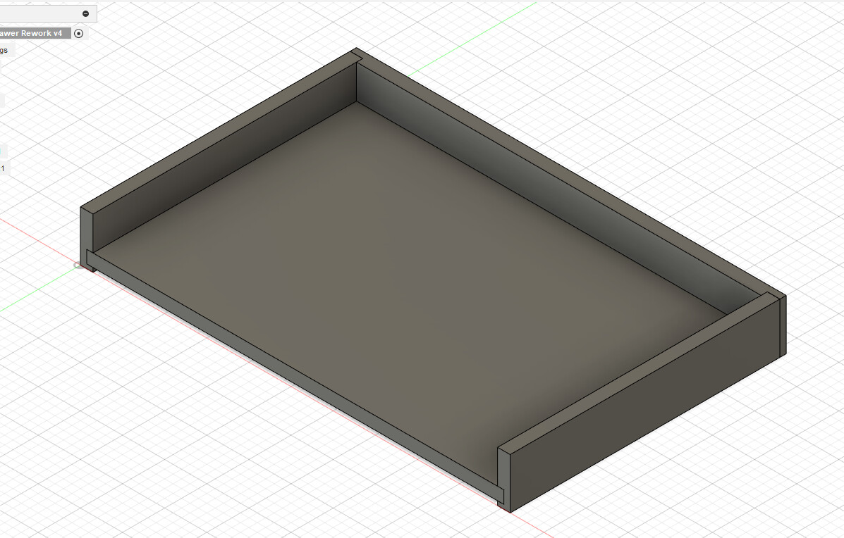
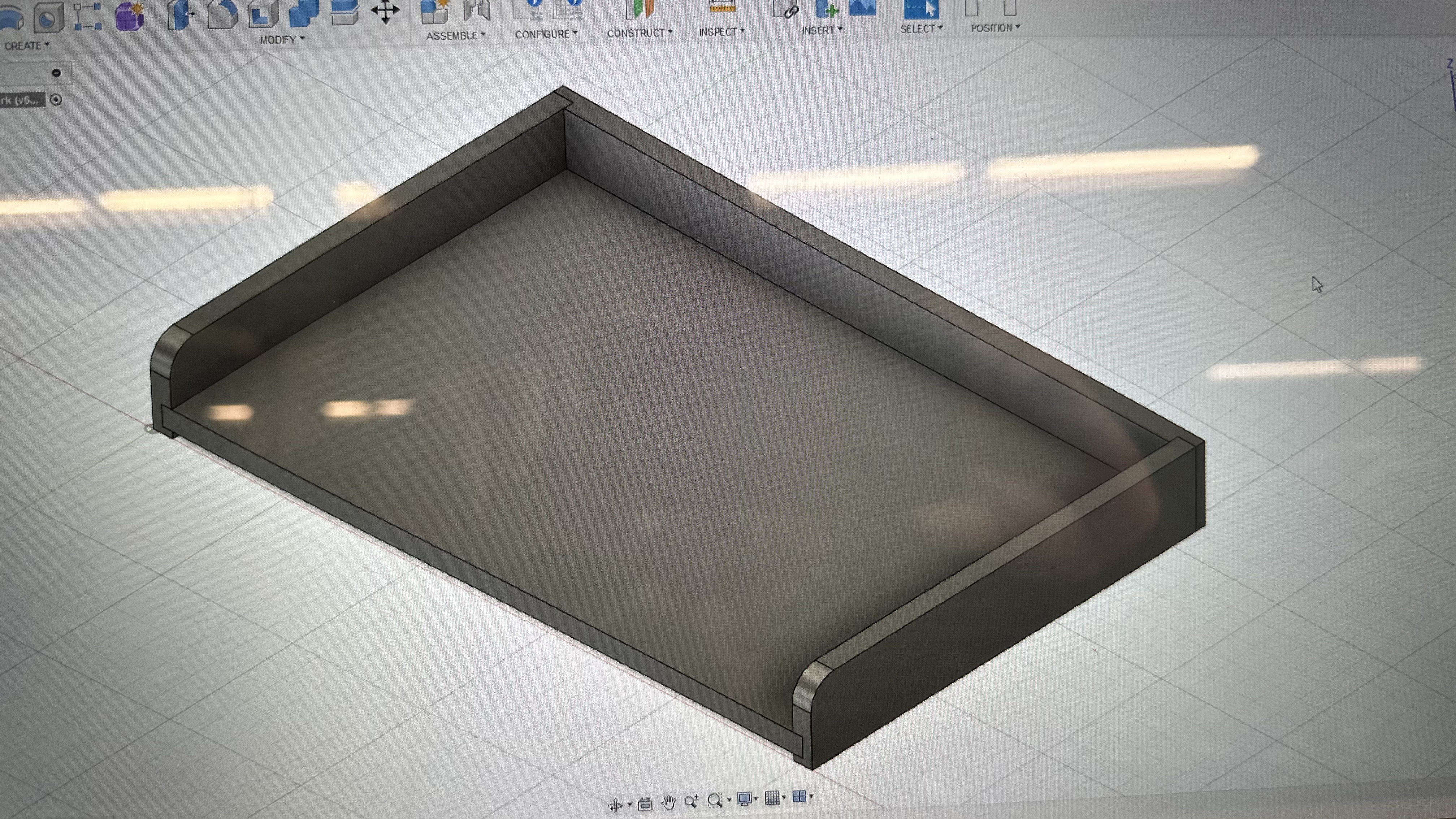
I’m using the free version of Fusion 360 and have designed a very simple drawer (a keyboard drawer, really) and I’m trying to figure out how to get from Fusion 360 to my LR4. If I can make this work, I’ll have more confidence in designing in Fusion 360 for “real” projects later.
So what’s the easiest / best way (circa 2025) to take a design like this and get it turned into G-Code?
So far, I’ve played with the CAM features in Fusion 360 and I was able to use @Flyfisher604 's latest post-processor to generate a file but it was what felt to me like a ridiculous amount of work – just trying to get the silly Z axis pointing the right way must have taken me 20 minutes or more. And while I think I got all the tools correctly selected, I really don’t know what speeds it’s going to use when I run the file – I haven’t tried running the gcode that was generated yet; that’s a project for tomorrow.
What about exporting “something” from Fusion 360 and importing to EstlCAM or some other tool (I have VCarve Desktop also)? Is there a process doc somewhere that walks a newbie through the steps?
edit: While you can’t export a model as a DXF, I do now see that you can export a sketch. I’ll see if I can figure out this “projection” stuff… Thanks, @Dreyfus.
I originally said: Can’t export DXF from the free version of Fusion. But thanks for the idea.
Hi! Can I export STL, OBJ and PDF formats on free version? When I tried doing it a few months ago it demanded an upgrade to a different plan
Yes you can, simply right click on a body or a component, choose “Save as mesh”, and select STL (Binary/ASCII).
.obj is also available in the Free version, click File > Export and choose Obj, or right click a body and choose Save as Mesh, and pick obj format there.
Instead of stl try 3mf its faster and ur slicer wont have a problem
…Any help? I don’t use Fusion so can’t confirm if any of these suggestions work. I still use the free 123D design which has no exporting restrictions. It is not a powerful as Fusion but it does for my needs.
This is the way. If you used a sketch to make your part you can use that sketch as well instead of projecting a new one. But a projected sketch is usually cleaner.
Did a quick youtube search and this was the newest video I found. But it does show how to do it.
just trying to get the silly Z axis pointing the right way must have taken me 20 minutes or more.
The learning curve to make this happen is a bit ugly, but once master can be done quickly. It is also ugly because you need to do it independently for all the pieces. Personally, so I don’t have to deal with the issue, I rotate all my parts so they are positioned with Z up like I want to mill them. Assuming you have set up Fusion 360 with Z up (highly recommended for both CAM and for 3D printing), this will be the default in the CAM, so you don’t have to deal with the issue. This also means you can set up the milling of multiple pieces. I do the rotation and positioning as the last step before CAM. If I need to go back and rework a design, I move back in history one step and insert the design changes. Most of the time, my changes do not impact the rotation.
What about exporting “something” from Fusion 360
As others have mentioned, you can right click on any sketch and export it as DXF. As Jonathan mentioned, the sketches you used to create the solid usually has many lines that you do not want to export. The solution is to create a sketch on the face of the object you want to export and then use the Sketch/Project comman on the completed solid to export only the edges you want. I get best results if I project individual edges. Sometimes if I project a whole body, I get double lines. I do this process a lot for laser work, so double lines means the laser will go over the same line twice. If you leave the projection linked and make changes before the projection in the timeline, when you go back and make changes to your original, the sketch you use for exporting will automatically be updated.
I’ve used a paid extension called Mapboards Pro that simplifies this.
Thanks Ryan for the suggestion. I was sad when the Arrange command was removed from the free version.
Have you all tried to create a 1:1 drawing of the parts and exporting the drawing to DXF? I no longer have Fusion installed so I can’t check if this works. But that is how I do it in other CAD software.
Make the 3D part → Use Sketch/Project to create a sketch with the desired lines → Right click on the sketch and export the DXF. I use this workflow all the time. In the free Fusion 360 version, you cannot save a project as a DXF, only Sketches.
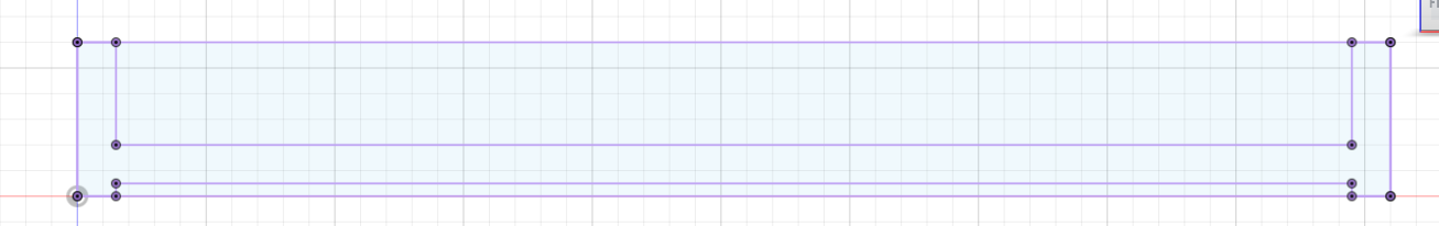
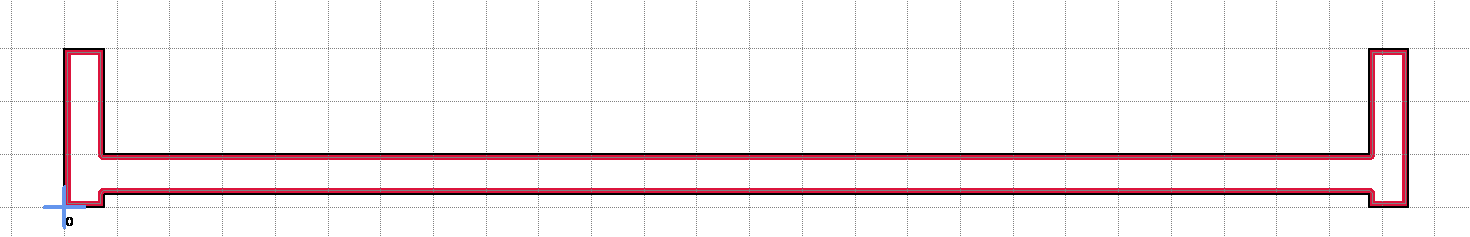
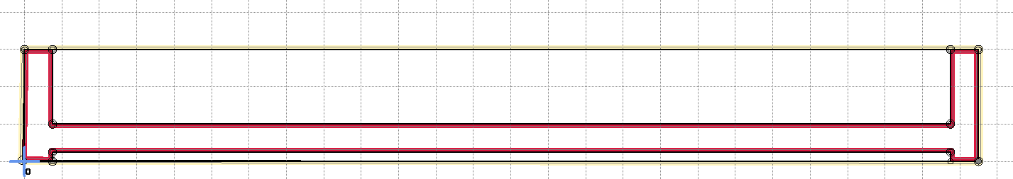
When I select the faces and do the “project” bit, then export the DXF, it looks correct but EstlCAM won’t find the “closed” polygon that I need to create as a pocket for the dado cut into the piece.
I need it to see the “H” shaped bit as a closed polygon that I can use the pocket tool on, but it just doesn’t seem to find it. I can move the mouse around and it selects numerous other closed polygons, but never then one I want… I also need it to see the entire outline so I can cut it out as a part; sometimes it does, sometimes it doesn’t.
I’ve tried selecting faces, selecting individual edges, selecting the entire solid and projecting each of those in the sketch, but the results seem to always be the same.
Estlcam lets you manually define profiles instead of automatically. When you do you can use left and right click to ‘follow’ the profile so it’s really quick to select the lines you want.
‘Manual shape detection’ the hover over tooltip explains it very well.
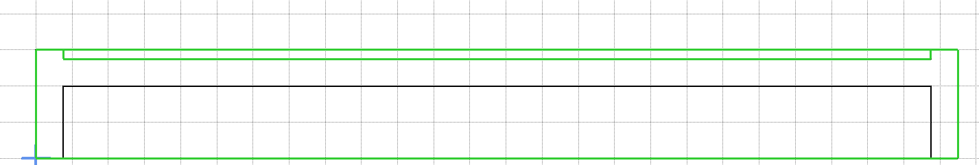
But I really need both the outline and the “H” – one for the pocket, the other for the cutout part. And I really hope that doesn’t mean I have to do two exports and two separate cutting jobs, as that’s just obnoxious.
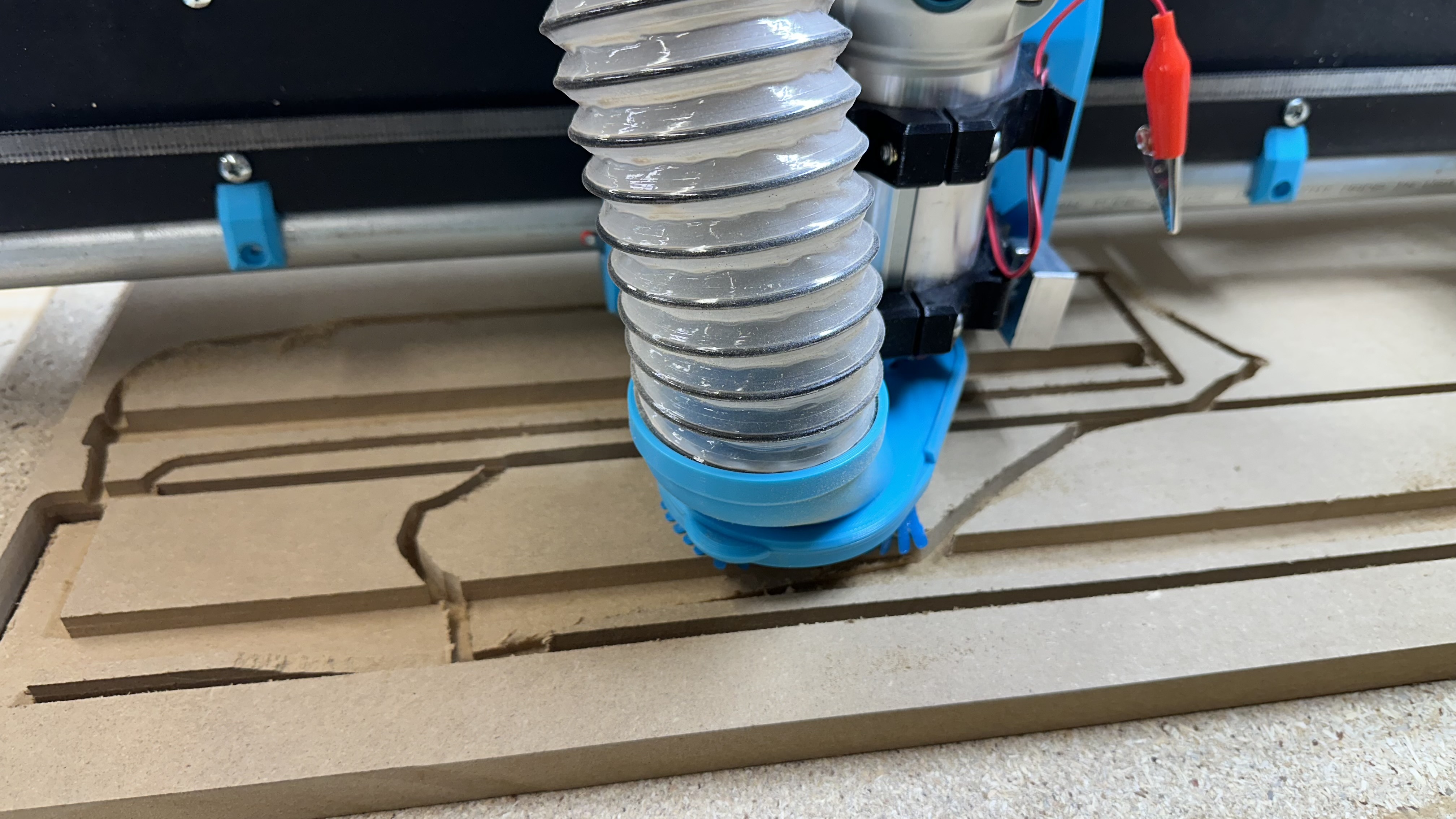
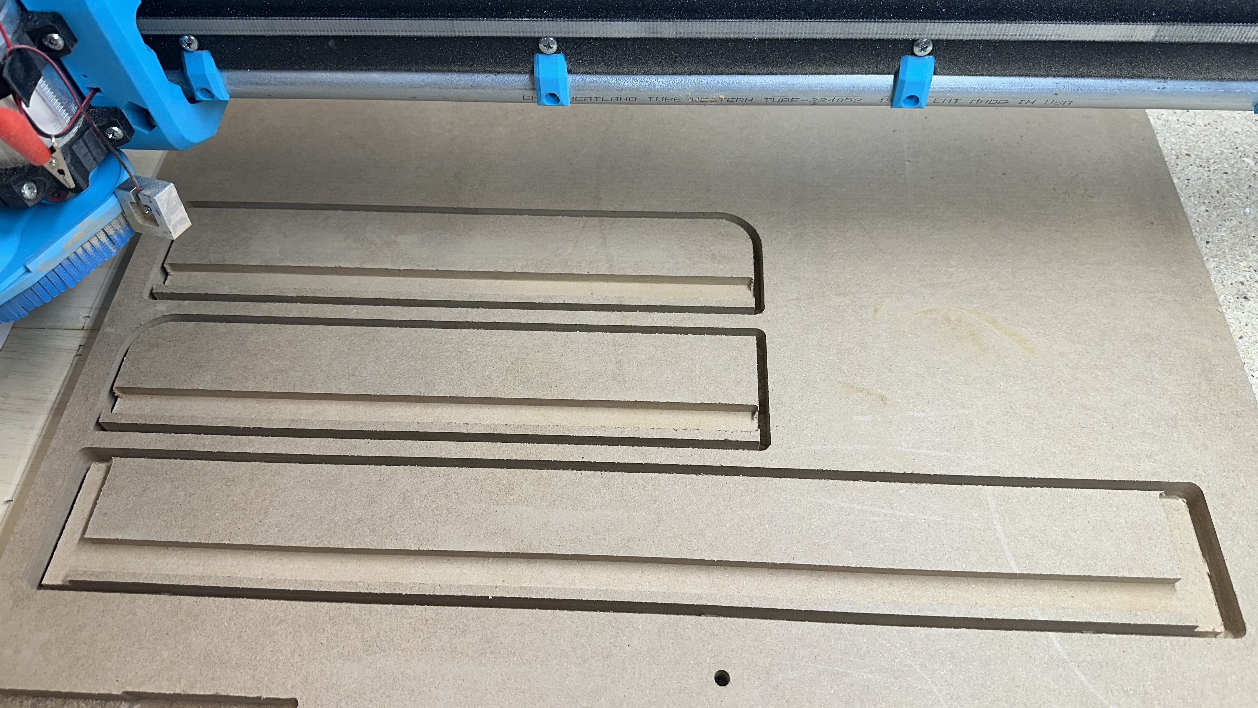
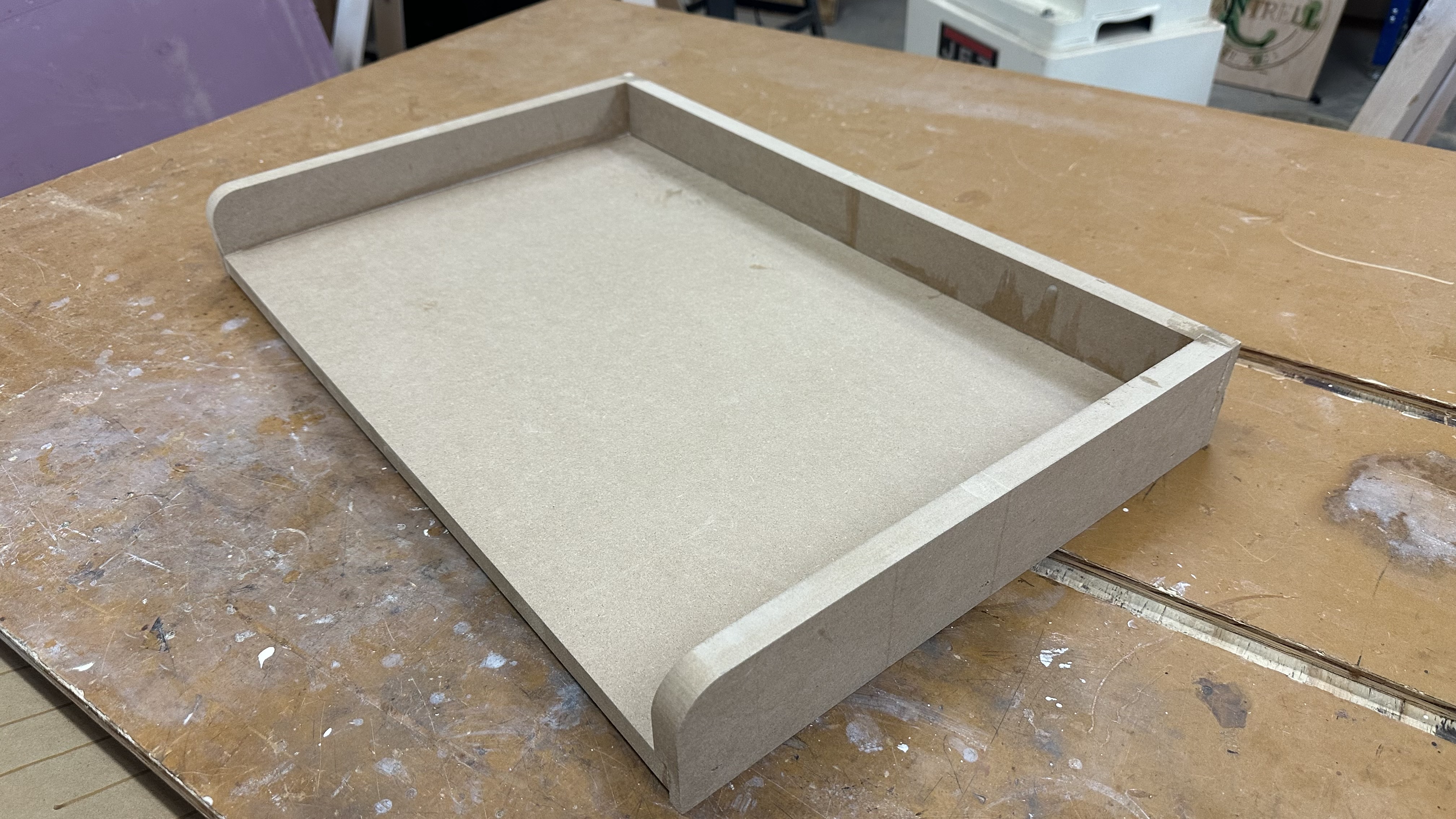
It took a few tries, but I finally managed to get all the pieces cut and assembled, and they (mostly) worked out exactly like I expected. Only thing I have to figure out at some point is why the .75" wide dados ended up about .735" – a bit too tight for the MDF I was using. But I made it work.