Does anyone know how to wire a Foxalien Smart relay onto a Jackpot board? Input is DC5V and comes with wiring for a Foxalien cnc but I figured I could just use those for the jackpot. I just need to know how to wire it up and activate it when starting a job.
Yes, we know how to connect peripherals to the Jackpot, but you’re going to need to tell us a bit more about your machine.
What kind of machine are you building?
What are you planning to run with the relay?
Do you have a link to the specs for that Foxalien Smart relay?
We need to know not only it’s required voltage but also how much current it draws.
Sorry about that I built a Lowrider 3 and I wanted to use this smart relay to automatically start the router and the vacuum when I start a job.
Here is the link to the store page: Smart Relay Controller Module for FoxAlien CNC
unfortunately I don’t have the specs with me they are in the box but I
did read on it that when it receives a 5v signal input it activates both plugs and when it ends it cuts off the plugs.

Do you have a 5V power supply floating around? If so, I’d start by testing it by connecting 5V to the Input connectors and seeing if it performs as expected. If so, that’s then simply ‘get 5V out of the Jackpot’, rather than figuring out this thing that most people are likely unfamiliar with an isn’t particularly well documented.
I would take a look at the existing connectors and attach +5V to the red connection, 0V to the other connection and verify that it turns the mains connection on by plugging in a lamp or something.
Thanks.
We also need to know the specs for your router and your vacuum. Those are 15A US 115V plugs, but with the router and vacuum you may be drawing at or above that. We need to make sure you aren’t going to overheat/overcurrent your relay box.
Maybe.
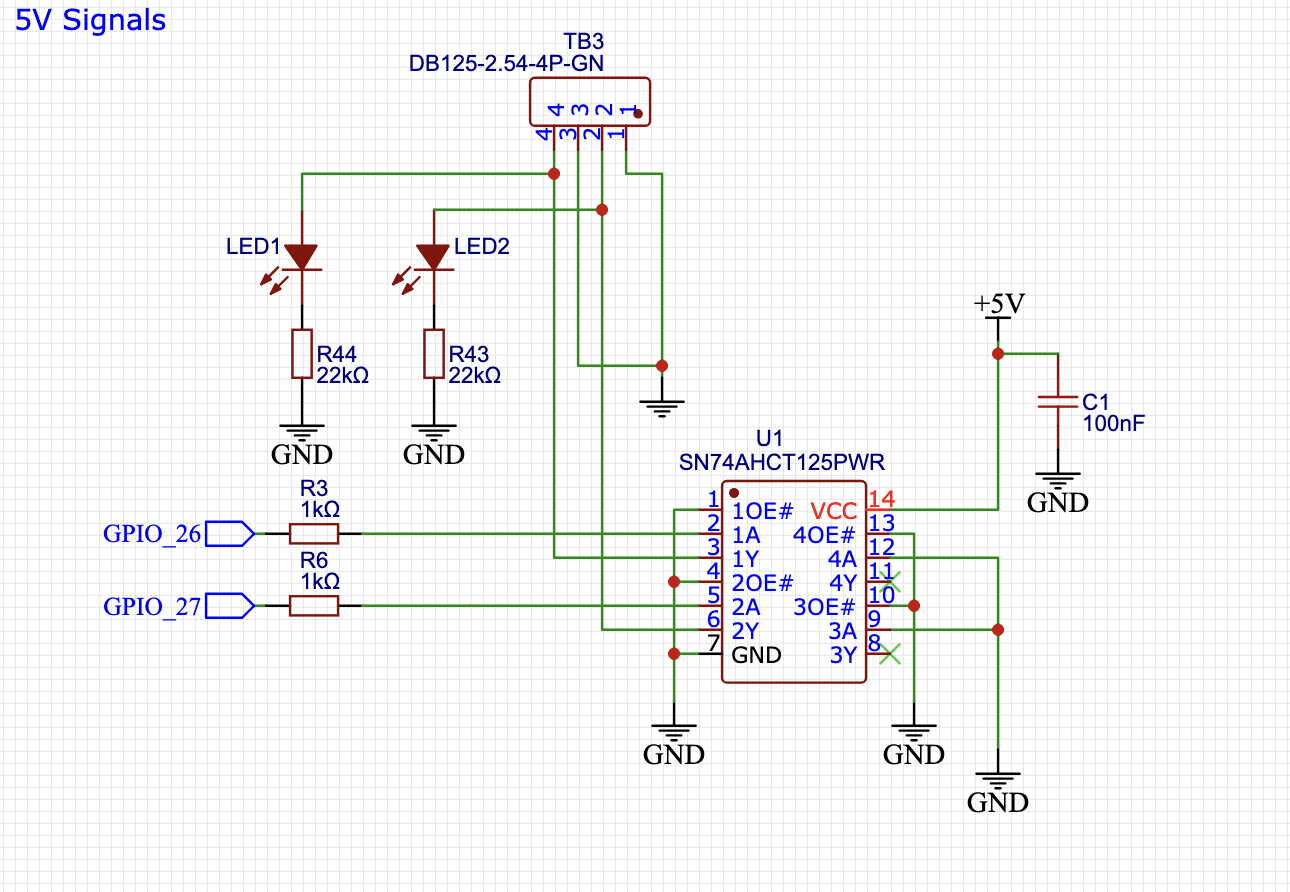
Jackpot 5V IO is sourced through a SN74AHCT125 buffer, and there’s no flyback diode protection.
If that 5V realy is a really low operating/holding current it might be OK, but I want to see the specs.
If the test 5V power supply above is used, we should measure how much current that relay box draws when on.
The MOSFET outputs on the jackpot are low side switched from VMOT, which would be either 12V or 24V, so those are not suitable to run this relay board.
I’m not sure I have a 5v power supply laying around I could use but I will try to get the specs for you guys, Thanks
Why would it need a flyback diode if it’s a driven CMOS logic output? Typically that would only be necessary for an open-drain or open-collector output.
More likely is that it’s not strong enough with only 8mA of drive available (assuming it’s just a relay inside), in which case the answer is still ‘how do we get 5V out of the jackpot’, it just also includes the need to provide a higher current driver, probably in the form of smaller relay or logic level FET/diode combo etc.
The relay outputs are a good point. I don’t see anything indicating that this won’t be low-side switched. Typically inputs like that should be entirely isolated. That’s likely a better approach.
Might be easier to just open it and take a photo? That’ll give us some pretty good hints. Does depend on whether you expect you might want to warranty it and how much something like that has cost.
Oh also I’m using a Makita 700 router and the vacuum is a small bucket shop vac like the one’s you just put onto any bucket
It was only 54 dollars when i got it so no big deal, I’ll have to open it up tomorrow while im at the shop.
It has a thermal overload built into it so I wouldn’t personally worry about overloading it.
I just found a tiktok where someone shows a brief ‘teardown’ of it where they opened it and kinda waved a camera at it roughly:
Tough to tell exactly what’s going on there or exactly how they’re implementing their 5V to 80V input but they clearly have a 5V coil relay on there that has 185mA of coil current. There’s a bunch of big electrolytics and what appear to be some passives and ICs so I’m guessing it’s a wide input range switching regulator to drop the input voltage to the 5V coil voltage. That’s a bit odd, honestly. I’d have rather seen a 110V coil relay driven by an opto-triac or something.
Either way, from looking at that it will need more current than the 5V input can supply so that’s out. It’s definitely entirely isolated so is find to be low side switched so it would be fine to drive from the relay drive mosfets. Those have flyback diodes but they won’t be needed given the input design of that board.
I would use the MOSFET connector and connect whatever the red wire goes to to Vmot and the other wire to the gpio pin.
Then all you should need to do is set that specific output high to enable whatever is connected through the box.
1 Like
I’ll give that a try, Thanks!
1 Like
Great detective work! Yes this is the way to hook it up.