I’ve been working on cutting XPS foam wings. The foam will be the core of the wing, and it will be wrapped in fiber glass later.
I need an aluminum tube going through the wing, so I decided to cut two halves with a slot for the tube. This is the first successful test piece (the back edge is a little rough, I made a mistake in CAM):
It’s a NACA0009 wing profile, with a chord of 120mm. That means it’s 120mm wide, and only 10.8mm thick at the thickest point. So the half shown in the picture is only 5.4mm thick. It’s a symmetric wing profile, so I will just mill two identical pieces and put them on top of each other.
I’m really impressed with the surface finish and accuracy!
Previously I’ve tried to hotwire wing sections like this, even on “professional” foam hotwire machines at a local fablab. Making a thin wing like this would be pretty much impossible and thicker wings would not be nearly as accurate.
Cutting wings like this was actually one of the main reasons for me to build an MPCNC, so I’m very happy it worked out!
It’s milled with a regular 4mm end mill with a flat bottom. I used a straight edge end mill. An upcut bit will probably work fine too, but I haven’t tried it. I do have a ball nose, but I was too lazy to do a tool change… First I surface the foam and cut the slot in one side. Then I flip it over, and cut out the wing profile. I just do both sides with the same end mill.
I used a 0.1mm stepover for the first 10% behind the leading edge, then 0.3mm until 25%, and 1mm for the rest. (If you look closely you can see that rightmost 25% is smoother than the left 75%.) The tool always moved along the wing, so parallel to the direction of the pen in the picture. My first idea was to move the tool perpendicular to that direction, but then you have to keep on changing the Z height all the time. The Z axis is relatively slow, so that limits the speed you can go. If you go too slow, you start melting the foam instead of cutting it. I used 40mm/sec. I might be able to go up to 60mm/sec, but 40 worked fine.
With the wing above I went from the leading edge to the rear edge. However, when I got near the rear edge, the foam just broke off (the CAM mistake I mentioned). So now I go from the rear to halfway, and then from the leading edge to half way.
The foam was held to my spoilboard using double sided tape. I got some “carpet tape” at the local hardware store. I cut small (like 1cm x 2cm pieces) and used 6 of those pieces for a 60cm long wing this morning. It held the foam in place really well. After cutting, I carefully pried it off with a putty knife. If came off very cleanly from the spoilboard and from the foam.
Tapered wings will be easy to cut in the same way I did. The trick is tiny stepover (and patience).
Be aware that such small stepover creates really fine dust. I used a dust shoe, and I vent outside. The filter clogs up pretty quickly.
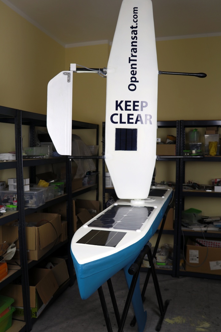
The idea is that a wing creates lift, which is normally used to keep a plane in the air. But when you use a wing vertically, the “lift” will actually push forward.
Besides the wing sail, I also plan to mill a rudder and fin in the same way. Those also use wing profiles (the rudder for low drag, and the fin for creating lift sideways which helps to keep the sailboat upright).
Oh and the hull itself of course! I built one previously using laser cut plywood and hand cut foam (with a handheld DIY foam cutter). This time it’s going to be way easier and better!
Very interesting! I was wondering about the thin symmetric airfoil. On aircraft the 0009 is common on tail surfaces, but the main lifting surface is usually more like 12% thick.
There’s some really cool tech in the sailing world. I find the foiling Moth class really interesting, and the canting keels used on the transat type boats these days too.
As for smoothness vs. stepover you can also mill the other way, and a shallow, nearly flat slope for the trailing half of the airfoil turns into a very shallow ellipse in theory, and you might get away with a larger stepover while maintaining extremely small cusps. In that orientation an ordinary flat endmill should be much better than a ball nose.


