Yes is agree I am just trying to get the steppers moving, my belts are lost in Amazon land. I didn’t quite have enough belt to finish so I am diving into this hurdle while I wait.
I am not teying to run any real sandify code or anything, I’ve just been giving it simple commands in the code box.
$X
G0 X0 Y0 F6000
G0 X320 ; Motors should make 10 full turns, same direction
G0 X0 ; Motors should make 10 full turns, opposite direction
G0 Y320 ; Motors should turn opposite directions
G0 Y9 ; and back
I dont actually type in the comments, but you should be able to copy/paste that and it’s all valid GRBL gcode
2 Likes
Dan that code worked and ran great.
And I re ran great after
Thanks
1 Like
I think I am just getting mixed up between
Gcode
Marlin and grbl.
I was assuming marlin was one style or language and grbl was another.
When iirc marlin and grbl are actually different “gcode” languages.
well now I feel a bit silly.
They are supposed to both follow the NIST standard for gcode. But they make different choices in the gray areas (and sometimes break the standard all together).
Both projects have large histories and have made their own compromises. Marlin actually started from the grbl planner codebase. But that was a decade ago.
1 Like
Thanks for the info, I often struggle with the wording and separating of things lol.
I just can’t wait till I get to a point where I can just export sandify patterns with a start and end code and have it run.
Damn belts supposed to be here on the 13 and now they are lost in the mail apparently lol.
But good time to dig into this stuff. I just have to be aware I have no end stops.
I am not a detail oriented person, generally. Especially when it comes to words and spelling. Off by one errors are something I really struggle with in my own code. That is part of why I am so good at designing fool-proof code. I write it in a way where I don’t have to worry about spelling or counting ![]() .
.
FWIW, I have endstops, but I have not installed them. I just move the carriage to the starting corner and set the zero for xy. Then I run a pattern. If it was already on, I can run another.
1 Like
I think I might have found one of my problems and if so oh man it’s a face palm.
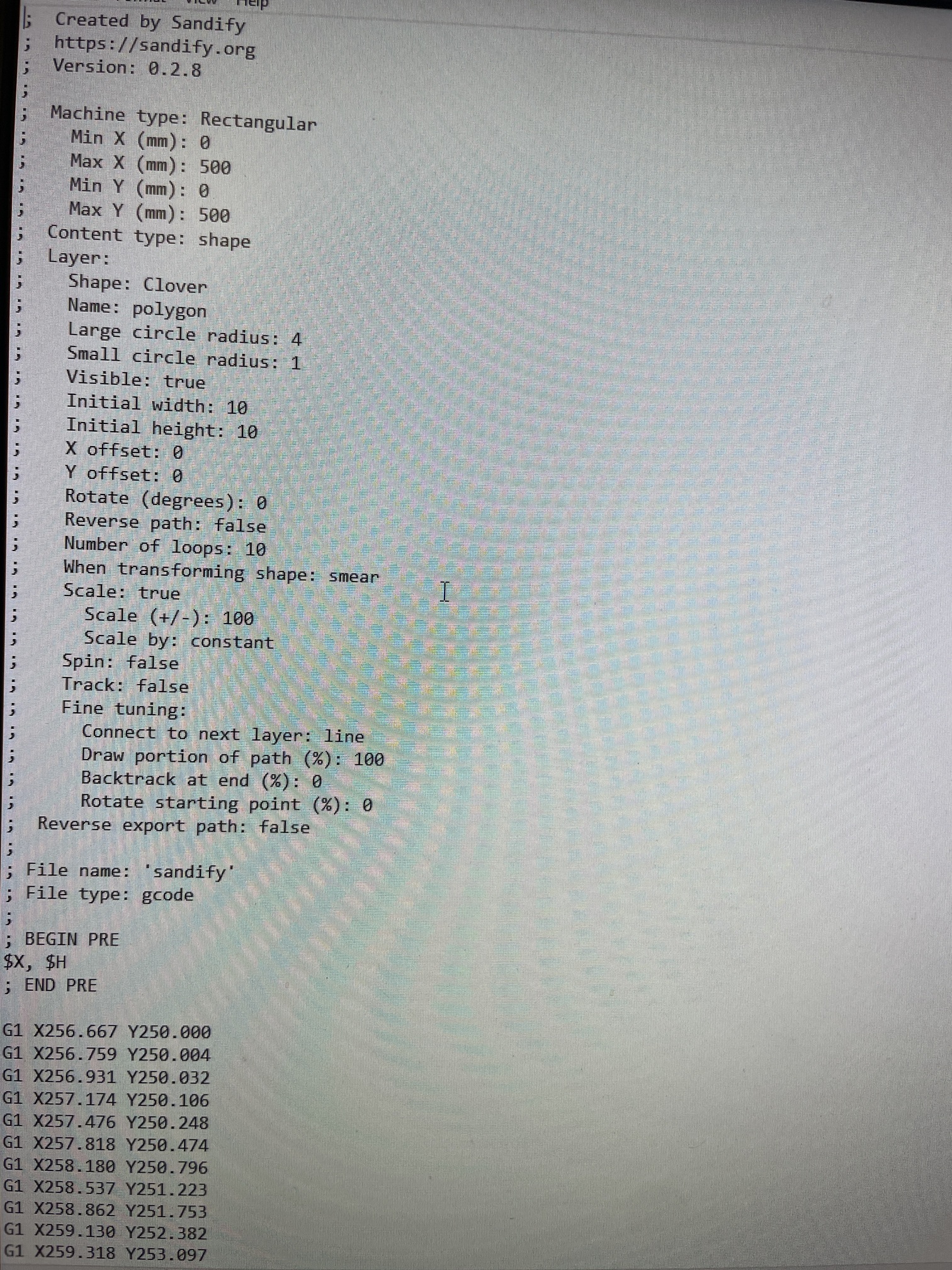
So the laptop I was running sandify on and using for my gcode.
Once I export via sandify then save it and when I opened it I noticed it was printed not word wrapped and landscape with all the g1 Commands connected.
I didn’t think much of it as I just assumed that’s how it was. Even tho I have my other files for estl cam and the ones I used for my other machines was portrait based and had single commands on lines.
At work on my break I was messing around and noticed it later it out correct.
My old laptop is a win7 based unit. So I am thinking there might be my issue as fluidnc is seeing one massive command.
Oh man if that’s it I will be mad happy lol
1 Like
And I have found my problem…… basically anytime I opened or created a sandify file using my win7 laptop it scrambled the gcode.
I am still waiting for my belt to arrive and if that all goes well I will go back through all this post and fix and get rid of all the ranting and make it like a total noob’s guide to Zenxy with fluidnc pen/laser board.
Thanks again for all the help
What browser are you using? The browser matters more than the OS.
I test in firefox. Bobnik uses chrome and safari.
It doesn’t even matter if I have it downloaded and saved on the sd card.
If I access it via webui
And download it, then open it, it’s scrambled.
Could be some setting that’s default on win7 for notebook.
But I have checked it on 3 computers now and the win7 seems to be the thing.
I will confirm tho that it’s not a internet program issue
It’s weird because I have used this laptop for the lr3 and made cuts with estlcam and even opened and edited the code to add the g38.1 touch probe command.
Bc mine was setup for the mpcnc and had the g28 in to auto write that in.
Well I am almost ready to start moving as I have received my belts.
I went to go and do a test run after I laced the belt in. And I couldn’t connect to my control board. I will have to use serial port and pull the start up sequence and see what’s going on.
It sounds like there has a been some issues with this and ppl added a restart feature in their code.
I have also heard about ppl just pressing the restart button on the board itself so I will try these tonight.
I also need to get my end stops wired up, now Dan had been so kind as to mention that I can just use the signal input pins on the board and then use the other wire iirc vcc to go from both switch to this terminal. Would this be correct or would I have to actually go in with platformio and change pin’s ?
(I really hope not lol)
The struggle is real sorry for all the spin off threads but I eventually want to consolidate this for all the other super noobs. And wanted to keep this about the board only.
No, you just need the 5V line to run tot he VCC of the optical endstops. You could bridge the ground as well, but no point to that.
So wire both of the power wires to the optical endstops to a +5V source on the TMC2209 board, then wire signal and ground to the X/Y end stop headers. I’ll be doing the same on mine.
1 Like
Thanks Dan
At lunch break I did manage to find some schematics.
Just best to ask before I let the smoke out hahah.
I think I read on some older posts are you also a northerner
1 Like
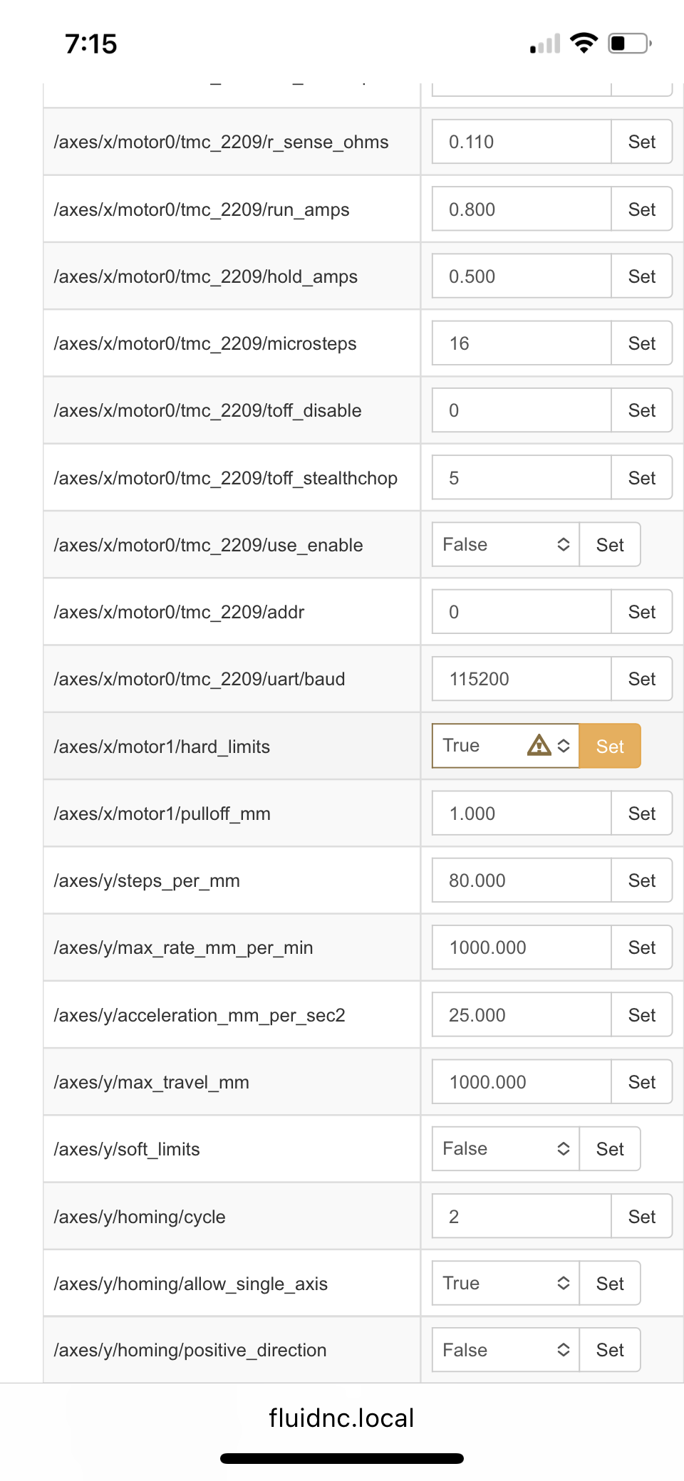
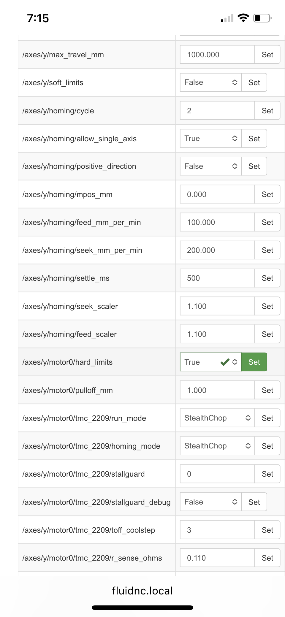
My end stops are not working and I think I know why.
I think within the config file I have to tell the board to allow the type of homing to use. “Hard end stops” you can’t save the changes iirc in webui under the config tab.
I think I remember someone talking about this before.
Like with
$CD=config.yaml
It won’t take.
Also look at how the stops are treated.
Typical switches use a pullup resistor to raise the voltage to logic high on the signal, and we use a switch to close a circuit to ground, which pulls the pin to logic low.
For our normally.closed switches, we trigger on logic high. Most of the time, the switch is connecting.thr signal to ground, so current flows through the pullup resistor and goes straight to ground. Logic low. When we trigger the switch, it takes away the low resistance path to ground, and the signal raises to logic high.
Active switches like the optical endstops don’t need the pullup resistor, and some can be kind of strange with it. The optical endstop might not have that low resistance path to ground, which results in the signal pin always being logic high if the pullup resistor is enabled. (Not all will have this problem, but it’s a possibility.)
With an active switch, either optical or mechanical, usually no pullup resistor is needed, and should not be configured. Most of these can be enabled or disabled in firmware, sometimes they are internal to the chip. I think they are built into the ESP32 in the chip or on the board.
So you need to check which way the stop triggers (I think these are logic high.)
Aha! I was just playing with my opto stops and the pen board. The default config.yaml file list for the X axis:
limit_neg_pin: gpio.33:low
This doesn’t work, it reads triggered when open and open when triggered. Change it to:
limit_neg_pin: gpio.33:high
I think the pullup resistors are configured and enabled, but it seems to be OK.
Also keep in mind that with a microswitch, it doesn’t matter which is signal and which is ground, but with these optical stops, it is important. My switches have a green light thst comes on when the switch should be triggered.
2 Likes
Thanks so much for the explanation. It would have taken me a lot of reading to get that figured out. I like the description !!!
And it would appear you are right I looked back at my start sequence. And if what you are saying is correct the Y NEG LIMIT low would never change even when I physically home it.
I will do some reading and figure out how to change my config file and save it and try these things.
I can’t state enough thanks
close older topics to help with spambots, and faster new user questions.