First off, a huge thanks to the team and community here for making this project, simply amazing. Secondly, I hope this isn’t too long of a post for my first post…
I’ve had my Lowrider V4 (~1.2m x 2.5m) built for about a month and have been relatively pleased with the performance when cutting mostly MDF. Until recently, my only challenge has been in trying to resurface the spoilboard using anything 3/4” or larger. I would always get tiny “ripples” running across from Xmin to Xmax. I figured out that my mainbody needed the tension bolts re-tightened and was hopeful that it had solved the problem (the body was tilting back and forth / front to back).
However, before I’ve tried surfacing again, I wanted to try out the build on some aluminum for a project I’m working on. No matter what I try (I’ve tried everyone’s settings that I have been able to find), I can’t get my build to cut aluminum. Watching it while it runs, it looks like the same issue (the main body tilts/shifts front to back). I’ve gone through and tightened everything and still same issues.
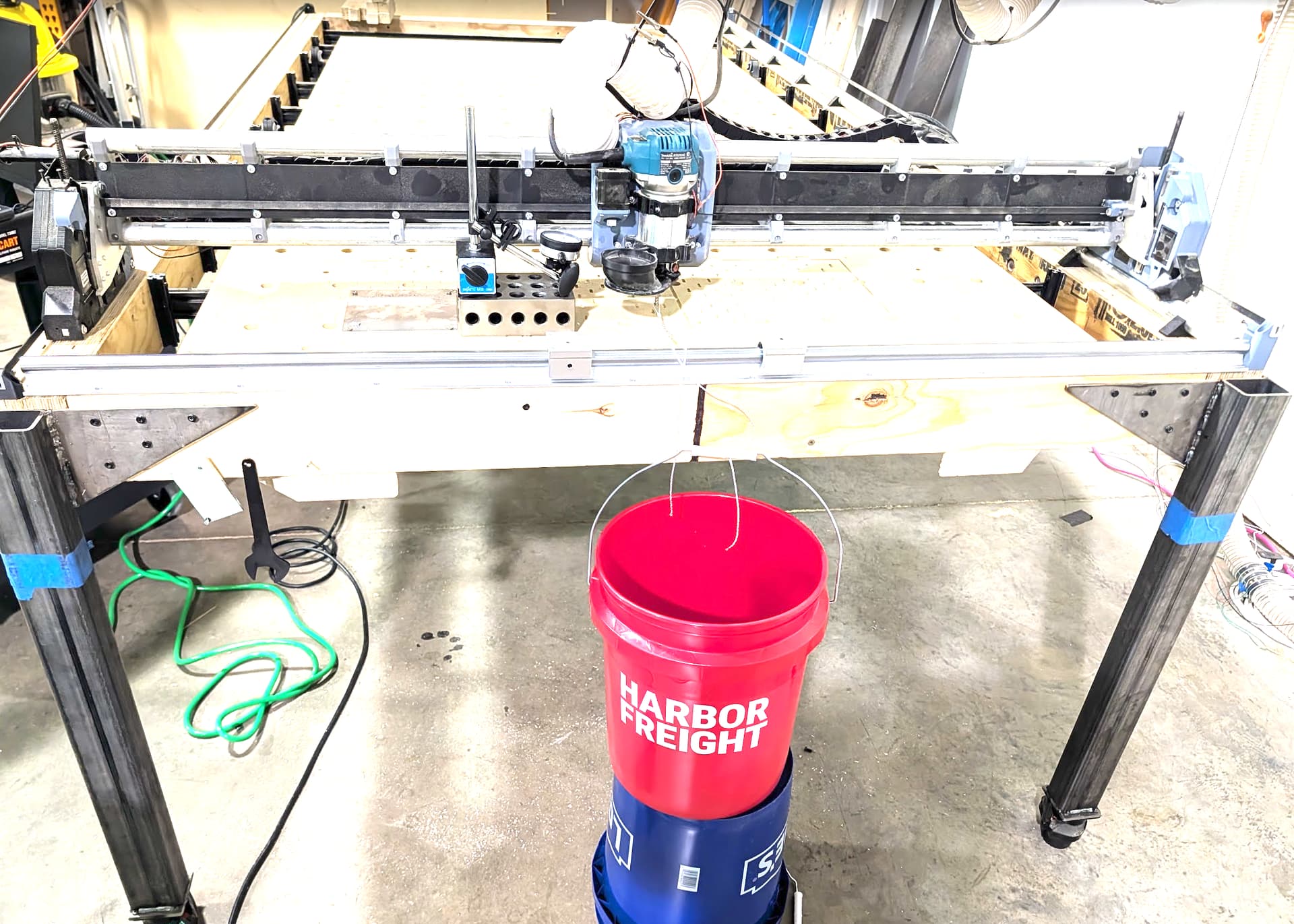
To try and diagnose the issue, I setup a relatively crude test.
I positioned the spindle/main body in the middle of the gantry, dropped my Z to approx. 75% of the way down (80mm from Z-home)
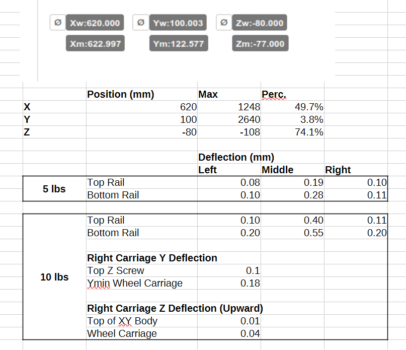
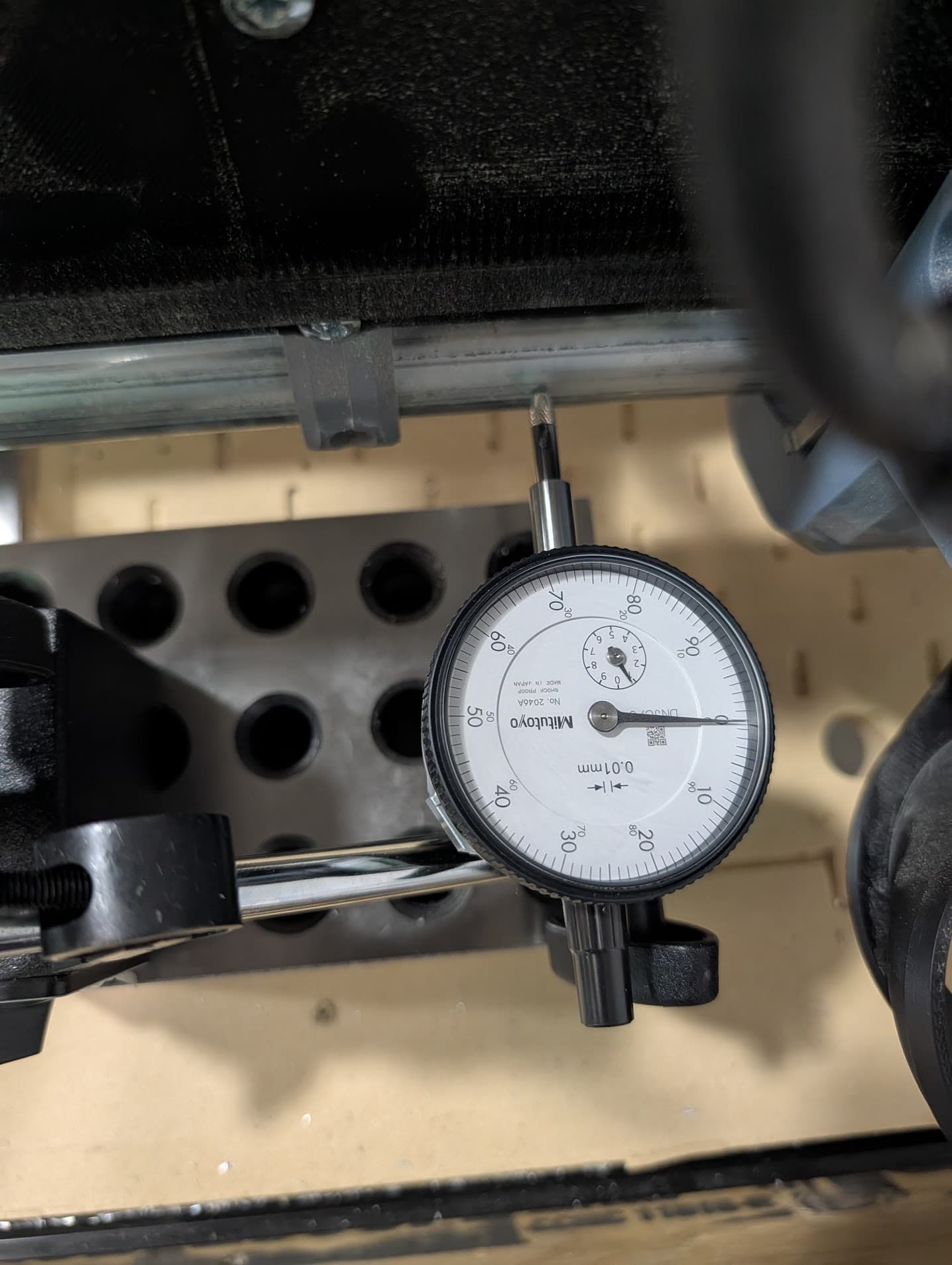
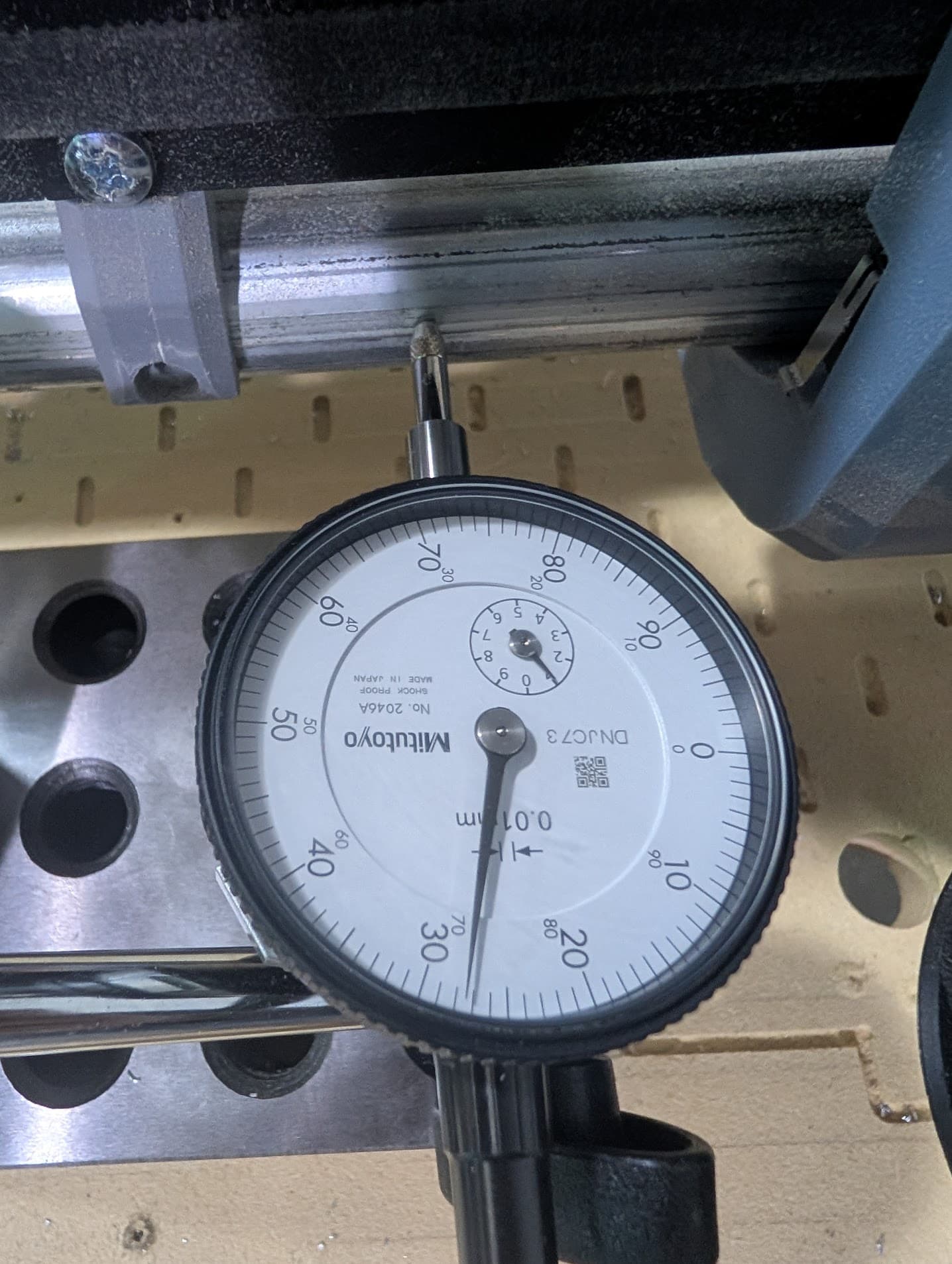
Using a dial indicator, I measured the displacement at 10 different points when a known force was exerted (5lbs/2.3kg and then 10lbs/4.5kg) at the base of the collet
I ran the “test” a few times in different orders of measurement to ensure the results were similar (on the first run, I did discover my X-max side belt was a bit looser than X-min, but that batch of measurements were thrown out of the averages).
NOTE: I did the 5lb tests first, once I got to the 10lb tests, I started wondering about the potential tilt of the XY carriages (i.e. a wheel lifting off the bed), so I did add some more measurement points in that batch (6 points of measure for 5lbs, 10 points measured at 10lbs).
Here’s a screenshot of the data. I’ll also upload a few pics of the test setup. I took a bunch in case they end up being helpful, but I don’t want to make this post any longer than necessary.
I guess my question is, do you think these deflections are “normal” for a Lowrider v4? I feel like this amount of deflection is likely abnormal as the forces I’ve applied are roughly withing the radial + tangential forces that the gantry would experience when cutting aluminum. And if it’s deflecting this much, it wouldn’t be able to cut aluminum (i.e. it would absolutely chatter like I’m experiencing).
Thanks in advance for (a) reading this far and (b) sharing any ideas you may have.
I didn’t put any of my initial impressions in the first post, as I thought it would be better to leave it a “blank slate” for reactions. A couple things jumped out at me.
I does appear that the gantry is flexing in the center, (the difference in deflection between the middle of the rail and the ends of the rail, noticeable in both the 5lb and 10lb test ).
It also appears that the whole assembly may be “lifting” off the bed, i.e. one set of wheels lifting up. I say this based on the additional measurements I did on the 10lb test.
In regards to the flex of the conduit/gantry, maybe that could be caused by a poor build (I missed something, need to tighten something, etc) and exacerbated by the width of my gantry (1.2m) . However, the lifting/tilting of the whole assembly seems like a pure physics/geometry situation and it’s should be independent of the size of build (the geometry of the XY bodies doesn’t change based off of build size, and it’s just based on the weight/base/leverage of those bodies to resist that type of torque).
Just some first/rough thoughts based on these initial measurements.
Edit to add a quick video showing the flex. It’s not of the test, just my brother putting a moderate amount of pressure with his hand.
Wow. That center bow is telling. How wide is your gantry? Did you make the interlocking strut plate for the underside? If not. I wonder if that would help.
The gantry is 1440mm wide (measured end to end of the EMT tubing). I didn’t know about the interlocking strut plates for the underside. Somehow I must have missed that part. I’ll check them out and maybe crank them out with so CF filament.
In regards to trochoidal, yes, I’ve tried that as well. I think the “most delicate” attempt (that still generated tons of chatter) was 12,000 RPM, 45deg Z plunge, 400mm/sec feed, 10% troch stepover, 35% troch width. Still didn’t work (well at least).
I would go tor an extra brace an Aluminum struts ( i have mibes already made vut cant find the time to stop working and Mount them. I would pist everything aboute yor vuild so we can all diagnose your build, thats a lot of flex snd i have 1.2mm wall full lenght x axis and im not there
Not everyone settings will work for you, you gotta do your homework. But i can tell: i do commercial work with a lowrider with expensive materials. It can be done:
Perfect v- route leaving just as much material as a razor blade. ( Im using a vacuum table for rhe v routing of course)
I mean with the right settings there should not be that high of cutting forces! Phillip hit the nail, and you JJ, 400mm/s i cant get that even with my big momma cnc
Yeah it trochoidal does go pretty slow. I still think your stepover was a little much. But if you have a ton of flex in your beam you have other problems.
While some people have been able to use large surfacing bits, in general smaller (1/2" dovetail) bits work much better. Wider bits will amplify any misalignment (tram), core looseness, and deflection. Note that some bit deflection is inevitable, which is why we do finishing passes on actual cuts.
This is not unexpected, especially with bits 3/4" and larger. You say they are tiny - can you feel them, or only see them? If the latter, then that is about as good as you can expect to get. If the former, there are ways to mitigate and reduce the effect:
tram the router to ensure it is perpendicular in both axis
use a smaller end mill (1/2"). This one is popular
cut in one direction only (the mill will deflect into the wood in one direction, and away from the wood in the other direction). @jamiek 's surfacing gcode generator is a good tool to use
reduce the DOC and feedrate to minimize deflection
When you say lifting, are the wheels lifting off of the table/rails? This could be because of excessive load (too deep DOC, too fast a feedrate, etc.)
This is not normal. The cause is usually the bearings are not tight against the conduit rails. They should be touching, with a light-moderate drag when turned by hand. If you can jiggle the core by hand and it moves, then they aren’t tight. Note that using non-standard conduit size can result in not being able to tighten the bearings sufficiently.
You will always get some flex in the gantry rails if you apply force to it. The longer the gantry, the more it will deflect under external force. The numbers you are getting aren’t of concern. My LR3 with 1" diameter 0.120" thick stainless steel tubes and extra braces will still deflect up to 0.5mm if I press it down by hand. I’ve learned not to press down on it by hand.
I just looked at your video. It almost seems like the gantry is “rocking” on the table. This could be due to a twist in the gantry (common) that results in the bearings in the YZ plates not all resting against the table surface/Y rail at the same time. Have you checked to see if one or more of the bearings aren’t contacting the table surface/Y rail when at rest?