One of the real advantages of the LR4 platform is its versatility… everything from 2.5D carving to full thickness cutting to slab flattening to sign engraving (and more!) Is possible.
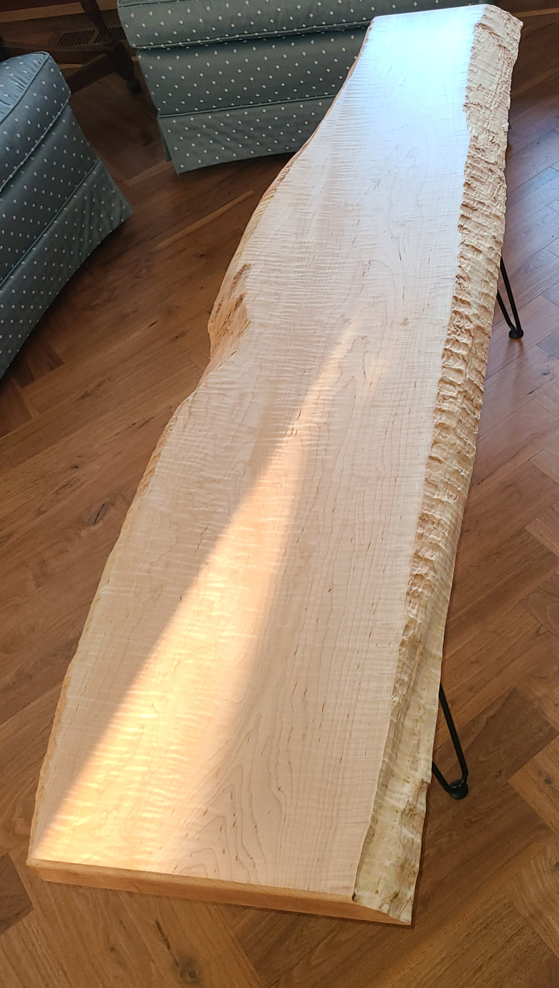
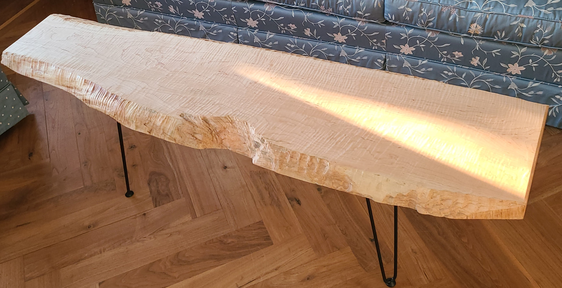
My current project is to make a table out of a 2-2.5" thick live edge maple slab that has considerable “tiger stripe” figure. It’s about 67" long and about 16" wide at the widest so it fits on my 72" x 42" LR4. The slab was somewhat twisted so it necessary to shim it for the first side.
In the following, I plan to show some progress pics and some results, but there’s also a sort of puzzle about which someone here probably has some insight.
To start, I’m using gcode from Jamie’s generator.
For the cutting, I’ve used three bits: a 0.5" straight bit, a 1" diameter, 3 cutter surfacing bit and a 1.5" surfacing bit with 4 cutters. This is where things got interesting, but that comes later.
Before starting, I confirmed that the gantry is pretty level by measuring the z height of my z-probe at the -x and +x extremes, which differed by less than 0.5mm after tweaking. I also attempted to check the x and y tramming of the router using the IDC 12"(!) Tramming jig, which in retrospect was far too long. That seemed pretty bad since it was off by ~6-8mm in both the x and y directions. But I decided to just “go for it” figuring that if there were steps afterward, I could just sand them away.
I did all the machining in the +Z direction as recommended.
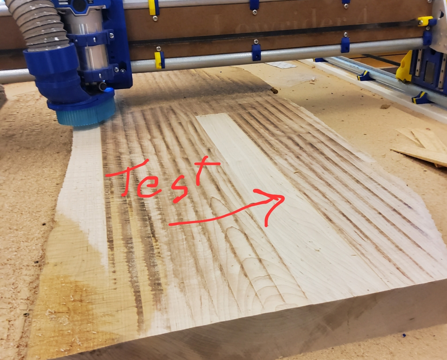
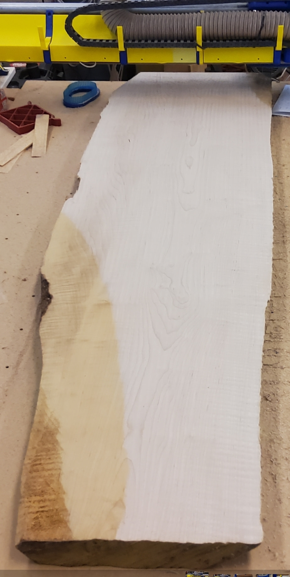
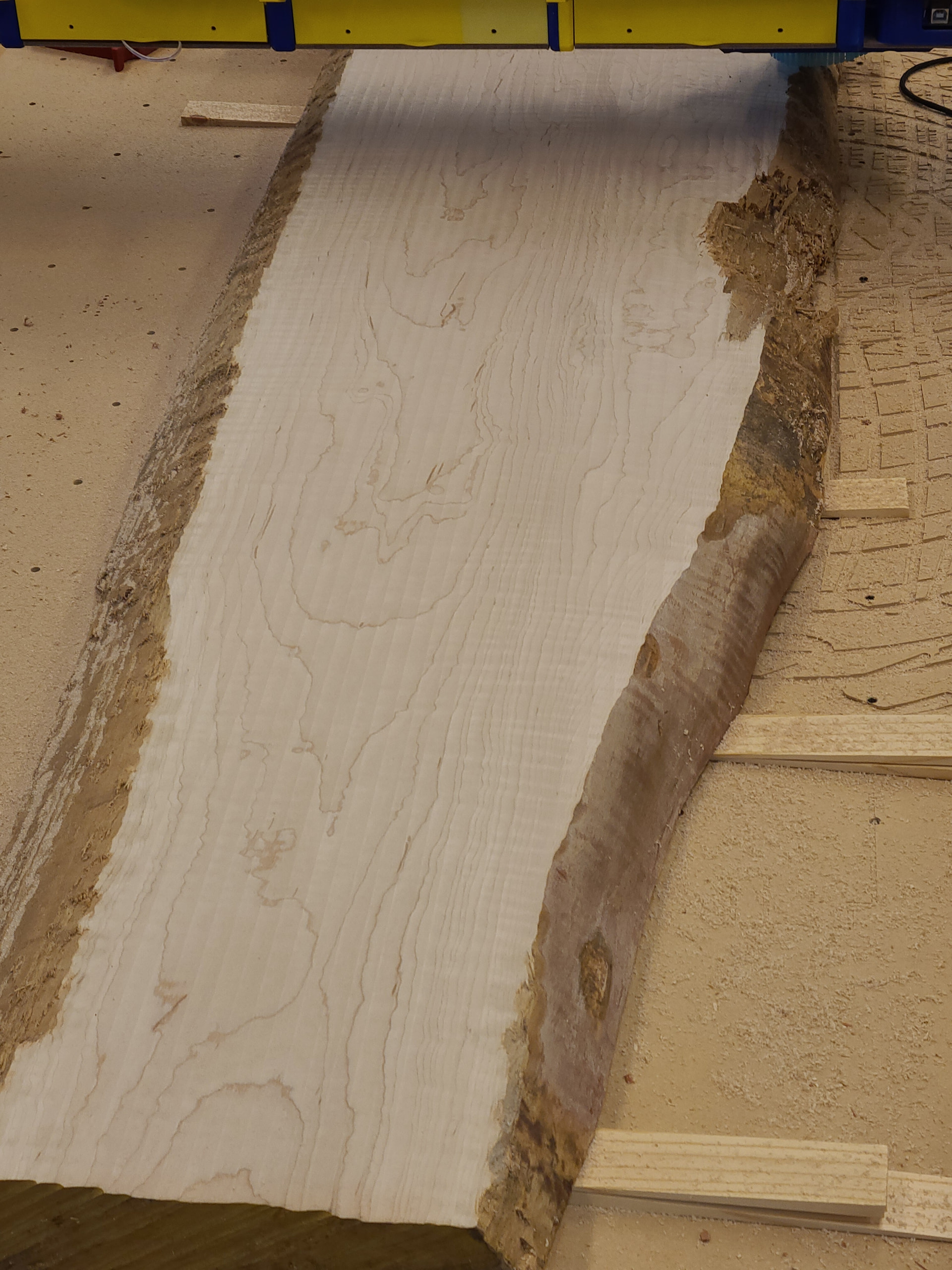
This picture shows the result after the first side was flattened using the 0.5" bit with a 10mm stepover. As expected there appear to be “ridges” between each pass; however, these are very subtle and can barely be felt.
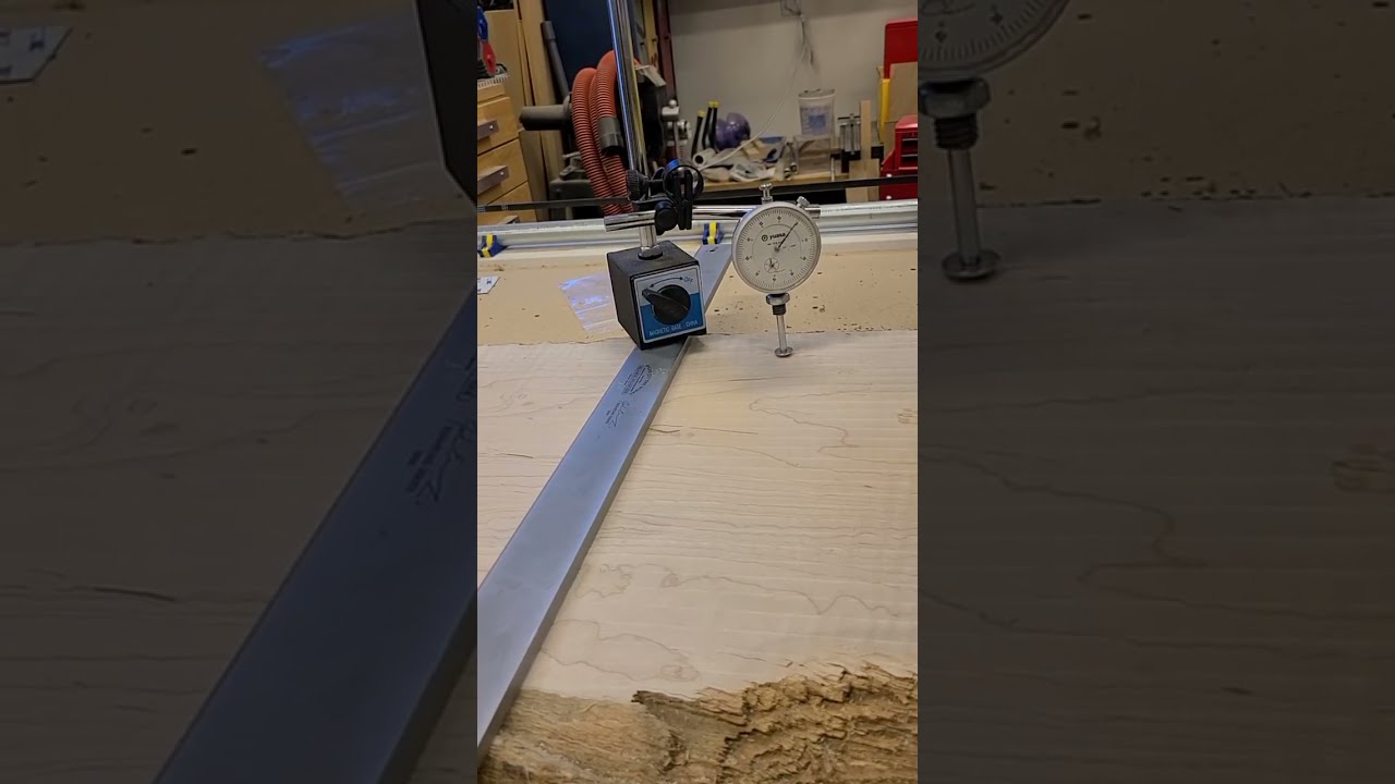
To try to decide how important this was going to be, I rigged up a dial indicator in a magnetic mount and attached it to a steel straightedge which was then dragged across the flattened slab. To my surprise, the fluctuations were less that 0.01"!
In the first reply, the attempted machining of the other side of the slab is shown.