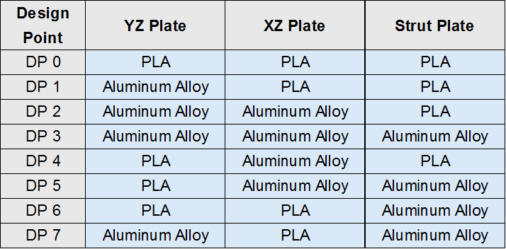
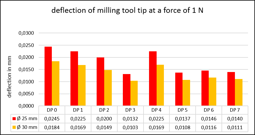
I would like to share some results of a finite element analysis of the LR3. The analysis was carried out with ANSYS and a 4"x8" build was modeled. The focus was to examine the stiffeness and how to improve it. For example to compare printed YZ plates and aluminium YZ plates. The geometry of both plates are the same, just the material was modified. The router is in X in the middle and in Y at the end, and in Z at the top (least rigid position). The deflection is measured at the tip of the milling tool. The raildiameters were modeled with 25 mm and 30 mm, the same direction like the LR4 seems to go ![]() .
.
11 Likes
Edit: Since the strut stiffness appears to be the single greatest improvement you can make (greater impact than condiut diameter), I would recommend going to aluminium
3 Likes
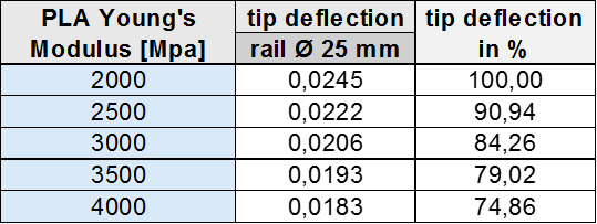
To examine the effect of different printing materials, the stiffnesses of all printed parts were varied between 2000 and 4000 MPa. The stiffness distribution is modeled isotropic. Note that in real parts there are different infill volumes and infill geometries, so that the stiffness of the part is less than the stiffness of the printing material and the part stiffness is orthotropic or at least transverse isotropic. But these effects were neglected in this analysis. But it is sufficient to examine the impact on the machine deflection/stiffness.
3 Likes
The greatest displacement due to self-weight occurs in Z-direction with 0,236 mm, and interestingly in Y-direction with 0,122 mm. The Y-direction results from torsion of the beam.

cheers Stephan
9 Likes
Nice work! It looks like th strut plates contribute a lot to the stiffness, more then I would have thought.
May I ask which program you use? I am learning some FEM at uni but we need to use Siemens NX but this program you use seems more effective.
Maybe it is also interesting to consider different 3d printed materials? For example pla-cf had a higher Young’s modulus then normal pla so I would be curious to see the effect of that.
1 Like
Welcome @DoSelbst ! Appreciate the time you’ve invested investigating and sharing this data. Cheers!
fwiw have seen many/most builds use MDF/Plywood for gantry struts. Have not seen any full length PLA struts, only the PLA temporary ones just to help bootstrap a build. Jonathan has a nice Alu strut that seems to work great.
1 Like
Something that would be really interesting to see is the affect on x gantry size. I’m about to build my table in preparation of building a lowrider and am having a lot of trouble settling on how large to make my x axis.
1 Like
We used Ansys a fair bit back in the day. We had probably $200k/year worth of licenses being used by one guy at the peak once you include all the high performance compute and parallel solve tickets. Our current place uses COMSOL which is a bit weirder until you get used to it but seems to have a much nicer multiphysics workflow which is useful if you start to add things like materials changing their characteristics vs temperature. It’s also a fair bit cheaper and WAY more permissive with the licensing around multi-core or parallel solving, or at least was when we were looking at it.
If you’re interested in it, my approach was to get a slightly less than legal copy of both, install them on an old spare hard drive then find a good Youtube tutorial for each and go through it. Going through the same process with both of them was really enlightening and also gives you a good feel for sanity checking the results which, having dealt with FEM simulations in the electromagnetic space for a couple of decades now, is probably the single biggest skill that’s missing amongst people in that area.
If you wanted a postgrad or final year topic suggestion, simulating and verifying a bunch of 3D printed materials would be a pretty cool idea and would get written about in a few places pretty easily. Being able to point to that kinda thing makes a HUGE difference in hiring decisions etc. Would get a bunch of real-world useful skills in the simulation area while also letting you build some stuff and get hands on with things which is fun. I doubt this is any kind of massively new idea or anything, so this might just be an electrical engineer rambling about barely understood mechanical engineering topics!
1 Like
This is brilliant! Really interesting. ![]()
Now do the LR4. ![]()
5 Likes
Actually that’s not a bad idea ![]()
2 Likes
yup, that’s the plan. But first I want to build a LR4. Then I could do a proper comparision of the improvements of LR3 to LR4 and I could benchmark my analysis to the real machine, but that’s properly many month away…
3 Likes
Yes, the deflection results from bending and torsion of the beam. Greater raildaimeter helps mainly with bending and the strut plates helps with bending and torsion.
That’s shown here:
Maybe the name PLA is misleading, the important is the young’s modulus. E.g. if you can improve your printed parts stiffness from 2000 to 3000 MPa (so by 50%), your machine will be around 15% stiffer. IMO if the printed material is a lot harder to print, it’s properly not worth it → see next comment.
yes, I couldn’t consider every variation. But the takeaway of this datat is, if you improve the stiffness of the struts from printed to aluminium, so around a 20 times increase in strut stiffeness, you get the shown results. If you use plywood or something similar, you increase your strut stiffeness by around 3 times, and you get a lot less improvement and leave a lot of machine stiffness “on the table”. Since the strut stiffness appears to be the single greatest improvement you can make, I would recommend going to aluminium.
Deflection by bending depents on the beamlength by the power of 3. So half your X-length results in a 8 times stiffer beam regarding bending.
Deflection by torsion depends linear to the beamlength. I didn’t yet investigate how the deflection is distributed into bending and torsion, but I will look into that, good idea.
8 Likes
Thank you for the ellaborate answer ![]() I might consider your suggestion for the final year project, which I need to do this schoolyear. I might be able to tailor it more to the v1engineering community by looking into both material and printing settings to gain the most ridged outcomes.
I might consider your suggestion for the final year project, which I need to do this schoolyear. I might be able to tailor it more to the v1engineering community by looking into both material and printing settings to gain the most ridged outcomes.
4 Likes
What thickness did you use in the model for aluminium? Since most people use strut plates of 6mm (1/4”) mdf or similar material. But 6mm thick aluminium would be at least 5 times heavier and also pretty costly. But 1-3mm aluminium would be more realistic.
1 Like
Thanks for the helpful work, and I look forward to LR4 analysis!
Comsol sales guys can hook you up with a time-limited full feature trial to learn it and decide if it will work for you. They gave me a trial and with some discussion offered to extend it. It wasn’t what I needed, and they were cool about it.
1 Like
Yeah, for sure. We did that and even extended it by another month when we weren’t able to make good use of the first month due to workload. I found that going the slightly less than legal approach was better for a slower learning pace and to familiarize myself with what the various abilities of the software was. For my own particular ethical purposes I didn’t use the results for anything commercial but it did mean that I was more comfortable making the choice to just rent a limited time Ansys license when we needed it for a consulting job.
2 Likes
great idea, have fun with the simulation! Feel free to ask if you run into problems. This data is from a bachelor thesis, more topics were covered.
Printing settings don’t impact the stiffness but the strength (unless the settings are way off), I did some tensil tests with shoulder samples. Soon I will add some PLA-CF, I can share the data when this litte project is finished.
2 Likes
I used 6mm for the strut plates, since I didn’t change the geometry, that would have been to much variation for the first analysis. The first shot were already 159 single simulations. But I won’t dig deeper into the LR3 since LR4 is just around the corner…
aluminium instead of mdf makes the struts 4.5 times heavier, but 26 times stiffer. But I agree, 3 mm aluminium struts seems much more appropriate
1 Like
closing old topic to help fight spambots