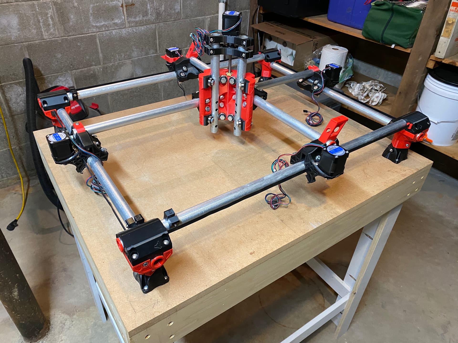
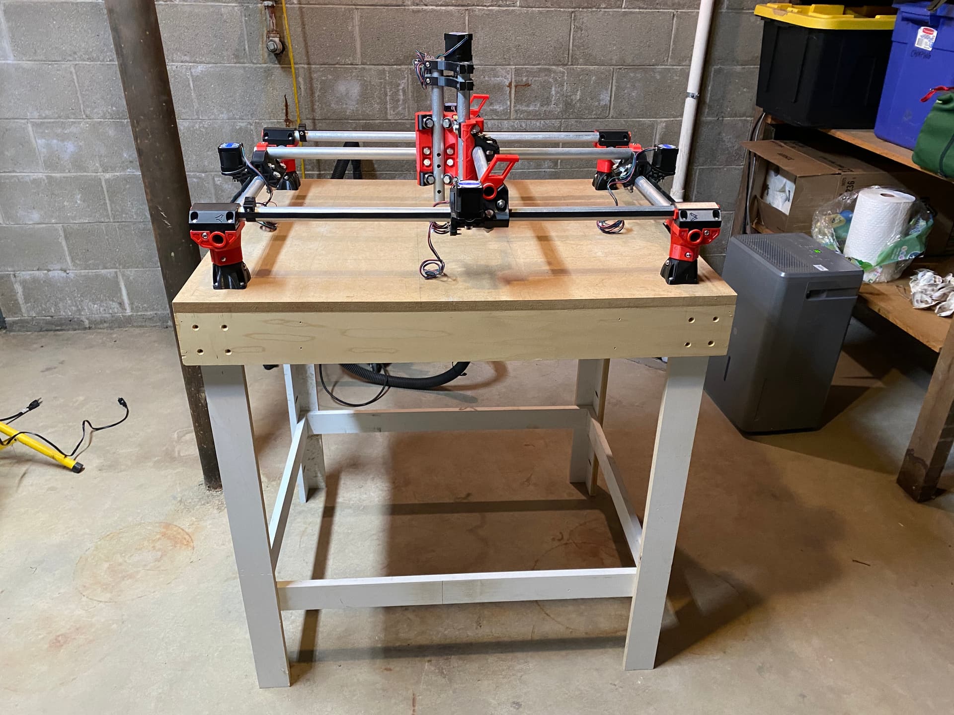
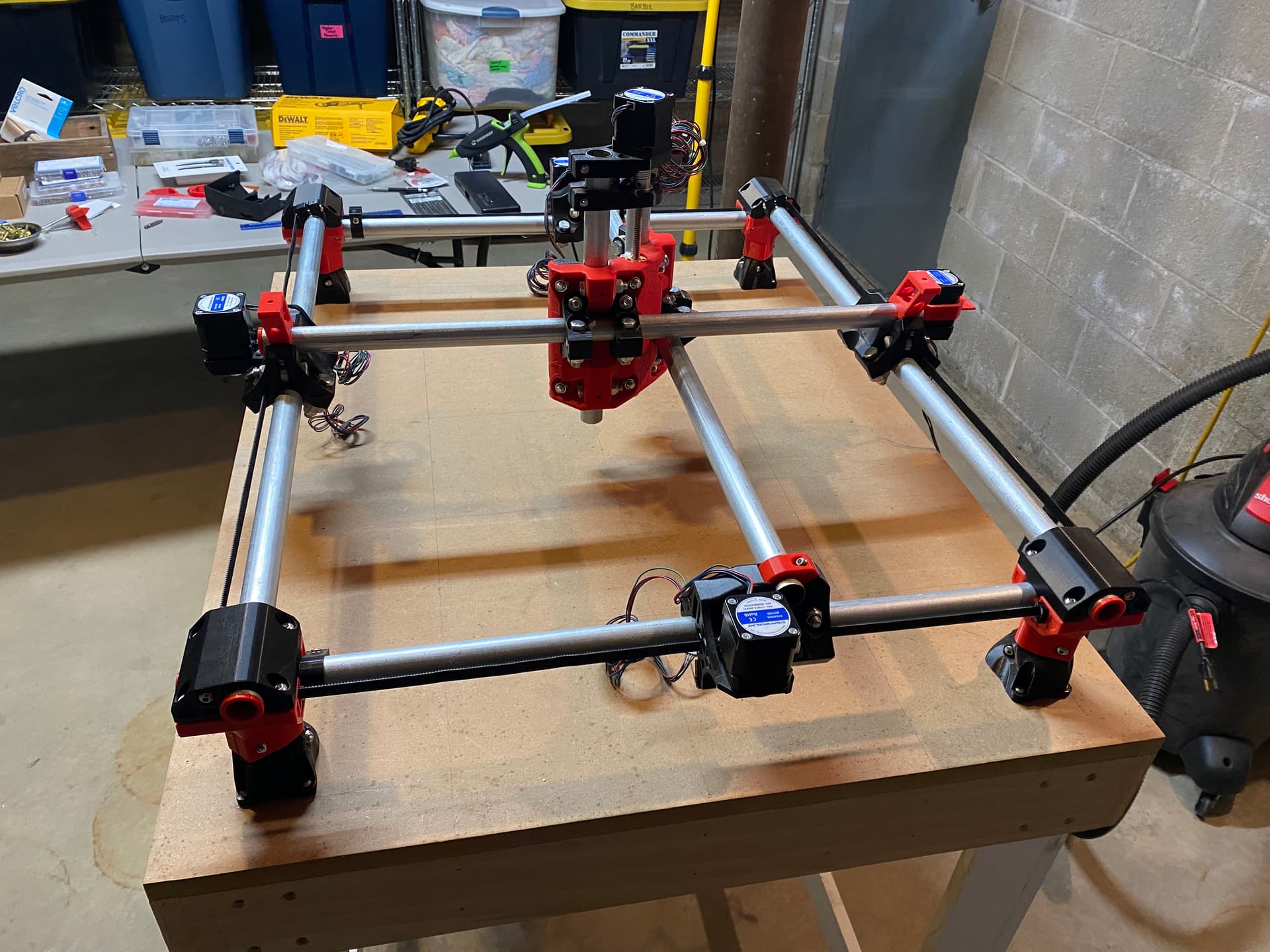
The finish line is in sight for completing my brand new MPCNC Primo. Foot spacing is about 83 X 65 cm. I have the DeWalt 660 router and clamps removed to rotate the lower portion of the router 90 degrees as Ryan states here.
I have a couple questions for the community.
Is there a preferred location to mount the Jackpot3 controller and associated case?
I have the V1 engineering wiring kit and will be using dual end stops. Can you share a document or tutorial for routing the wires and connecting them to the control board?
Does anyone use an iPad to control the MPCNC? If so, do you like it? Any suggestions?
Hi, first post here as I’m also in the process of building my first machine.
Printed everything and got the controller board couple of days ago so I’m in the process of reviewing again the instructions before starting. Point 1 and 2 are not stated in the documentation which I found a bit lacking just on this topic so far. I’ll post here what I’d do at this point but hopefully you already figured it out or someone can confirm.
From observations of built machine photos the controller box is in one of the corner, usually on the back (opposite to home 0,0) because 2 of the motor wires are fished through the gantry rails to join the motor wires on the opposite side. My guess is it can be placed anywhere the wires reach. Just be mindful of the gantry motion.
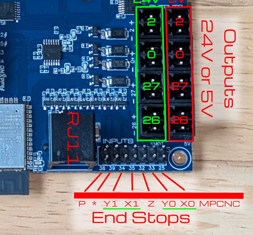
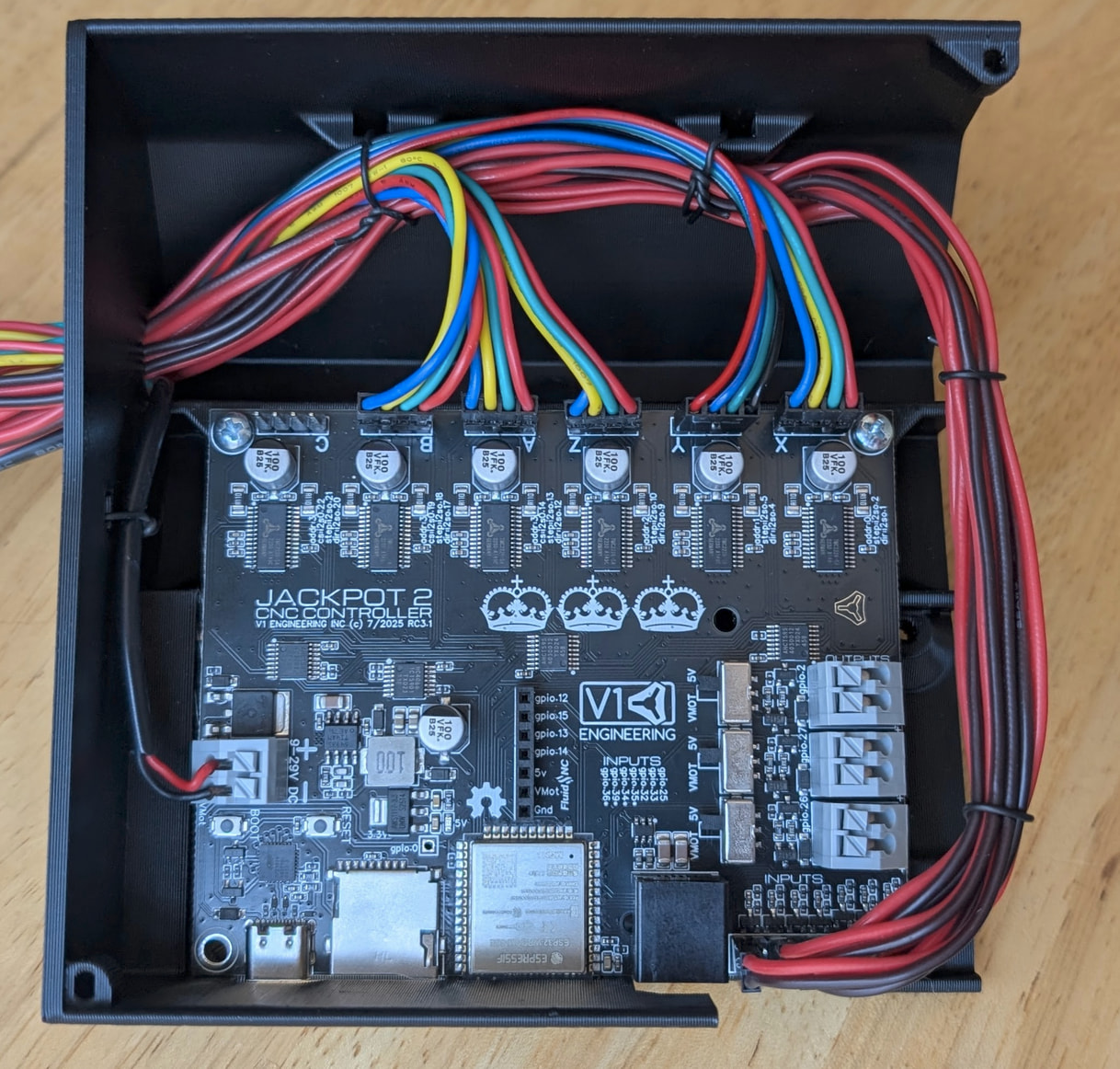
Having trouble finding endstops locally at decent prices I’ve dug on those a bit. Here you can find the pins for the endstops wiring. I don’t see a Z endstop from your photos so you should connect just X0 X1 Y0 Y1. I’m guessing according to how you connected your X and Y motors, so motor X0 will pair with endstop X0 and so on.
For the wires I had to ask AI. If not mistaken the jackpot3 requires NC so only 2 wires need to be connected (the endstop will shortcirtuit them internally and will open the circuit when triggered).
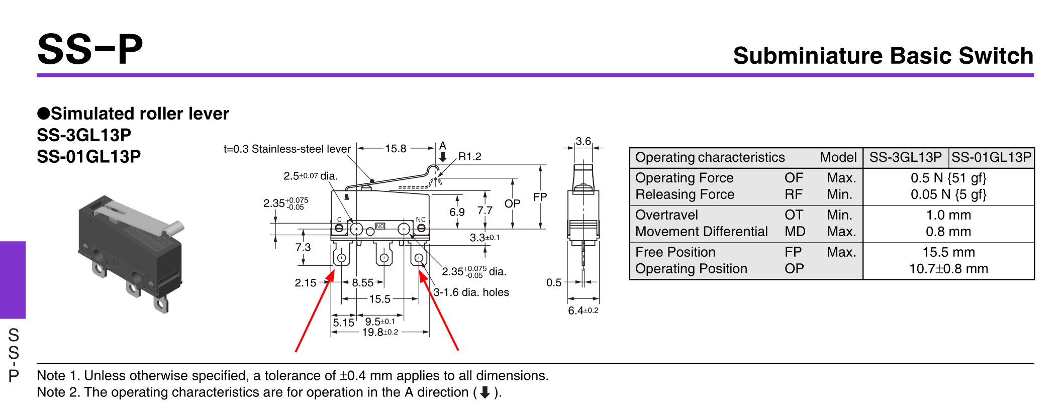
From the datasheet I gathered that pin 1 and 3 should be the ones to connect to the board. Anyway you can check for continuity using a multimeter.