"Filament Inlet" in acrylic / plexiglas IKEA Lack-based enclosure (for BIQU B1 or other printers)

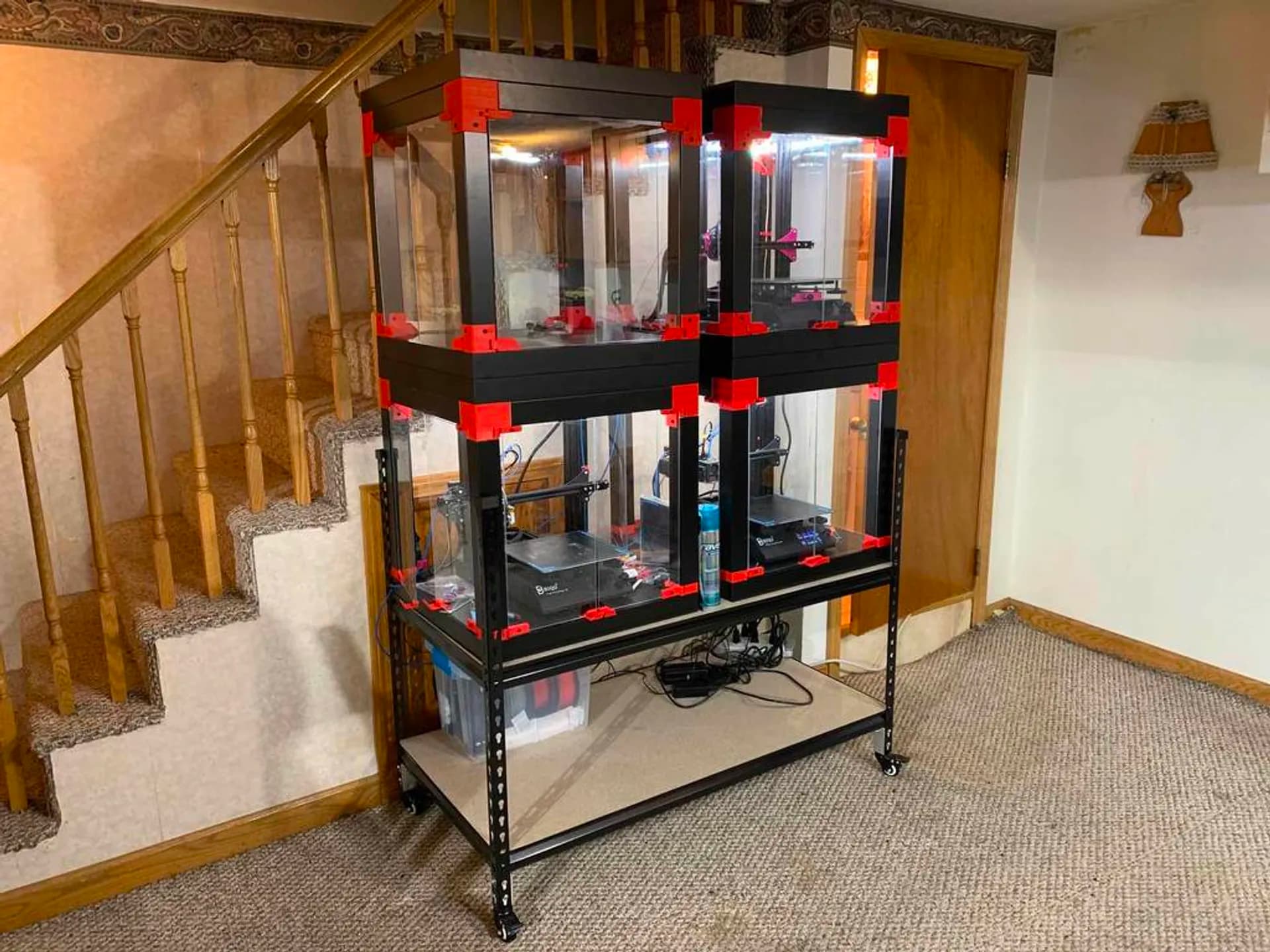
I have a bank (mini farm) of 4 BIQU B1 printers in a 2x2 stack of enclosures made using the super affordable IKEA Lack tables.

My enclosures are based on enclosure designs by Prusa, which were shorter in height (for their shorter printers, and too short for a BIQU B1), and were designed to have the whole enclosure lift away from the base of the enclosure.

My v1 enclosure design, which is tall enough for a BIQU B1 (and other similar height printers) kept the lift-away feature, but I really did not care for it. Moving the thing was frustrating. It was wobbly, not stable, and with the enclosure lifted away from the base, the top part felt fragile and unstable.

(V1) For BIQU B1 - DIY Enclosure - Remix of Prusa’s IKEA Lack Enclosure - with extra doors (opening on 3 sides)

image

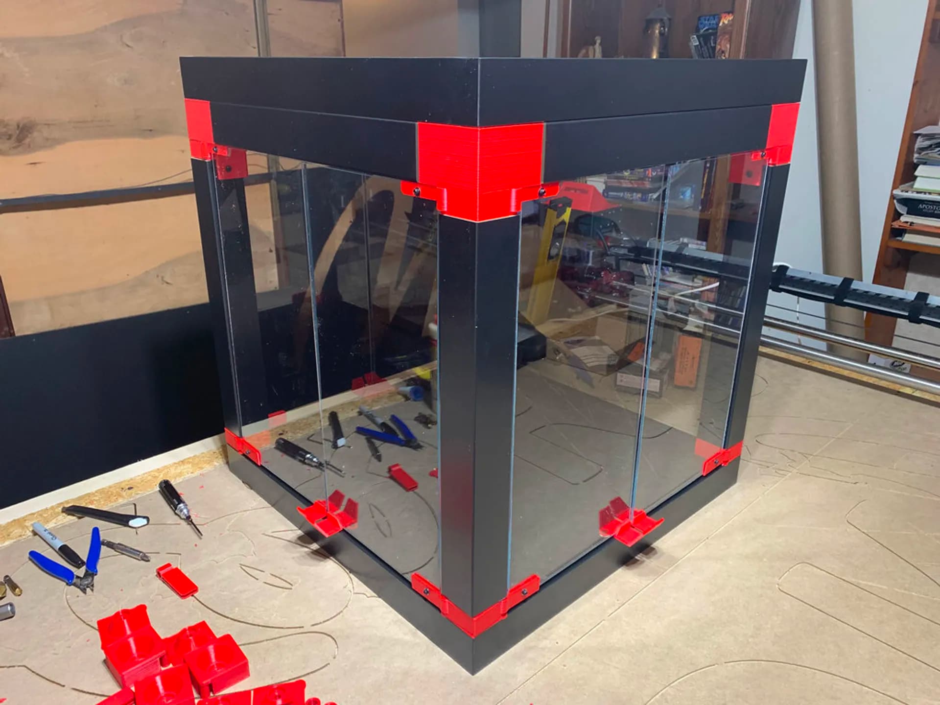
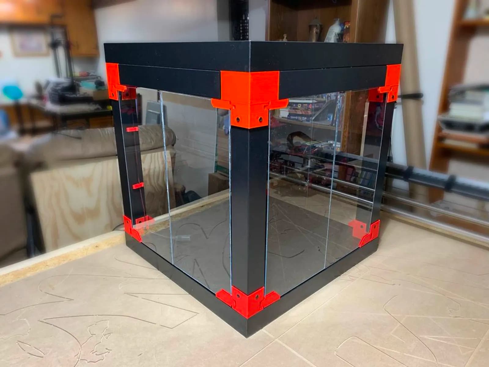
In my v2 enclosure design, I fastened the enclosure top to the base. Access is via the doors on 3 sides out of 4. The printer can be removed from the enclosure as needed (through the front access doors) and then returned. I liked it much better, and have been happily going along for a couple years or more.

(V2) For BIQU B1 - DIY Enclosure - Remix of Prusa’s V2 IKEA Lack Enclosure - with extra doors (opening on 3 sides)

image

For a variety of reasons, including space limitations, ease of access, convenience, etc, I installed filament holders outside the enclosures, with inlet holes drilled in one of the side doors on each. At first I was placing filament rolls below the enclosures, with inlet holes drilled lower on the given plexiglas door. Then I switched to attaching the filament holders at the top of each enclosure, with inlet holes drilled higher up.

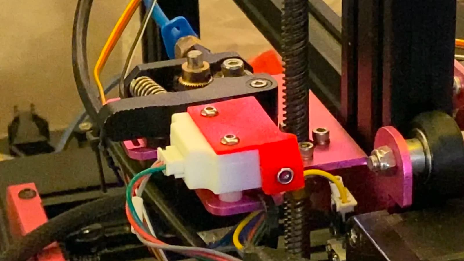
This worked great, and there were no problems… except over time, the passage of filament erodes. I do a lot of printing. The erosion was first noticeable in causing the stock filament runout sensors to be unusable, because the erosion at the inlet on the sensor allowed the filament to bypass the sensor path. This led to my design of the…

Runout Detector Saver v1.0

image

That worked great. But lately I began to notice that erosion was also happening on those holes I drilled in the plexiglas.

First, let’s look at what did NOT work.

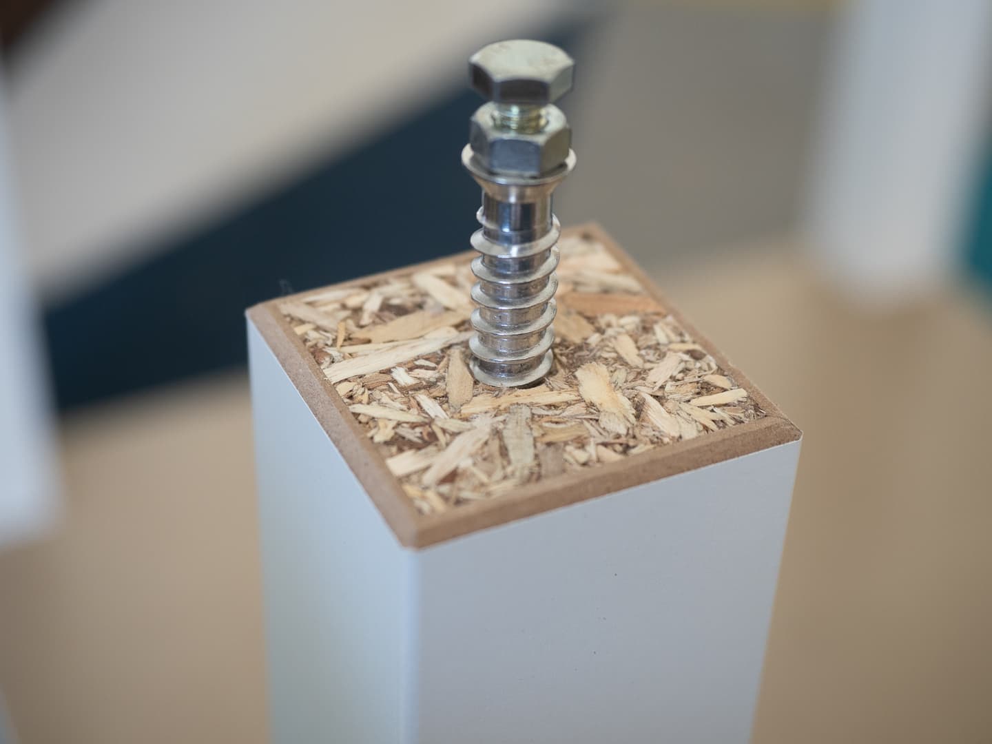
I designed a 3D printed “Filament Inlet for IKEA Lack-based enclosure” — seen here in these pics:


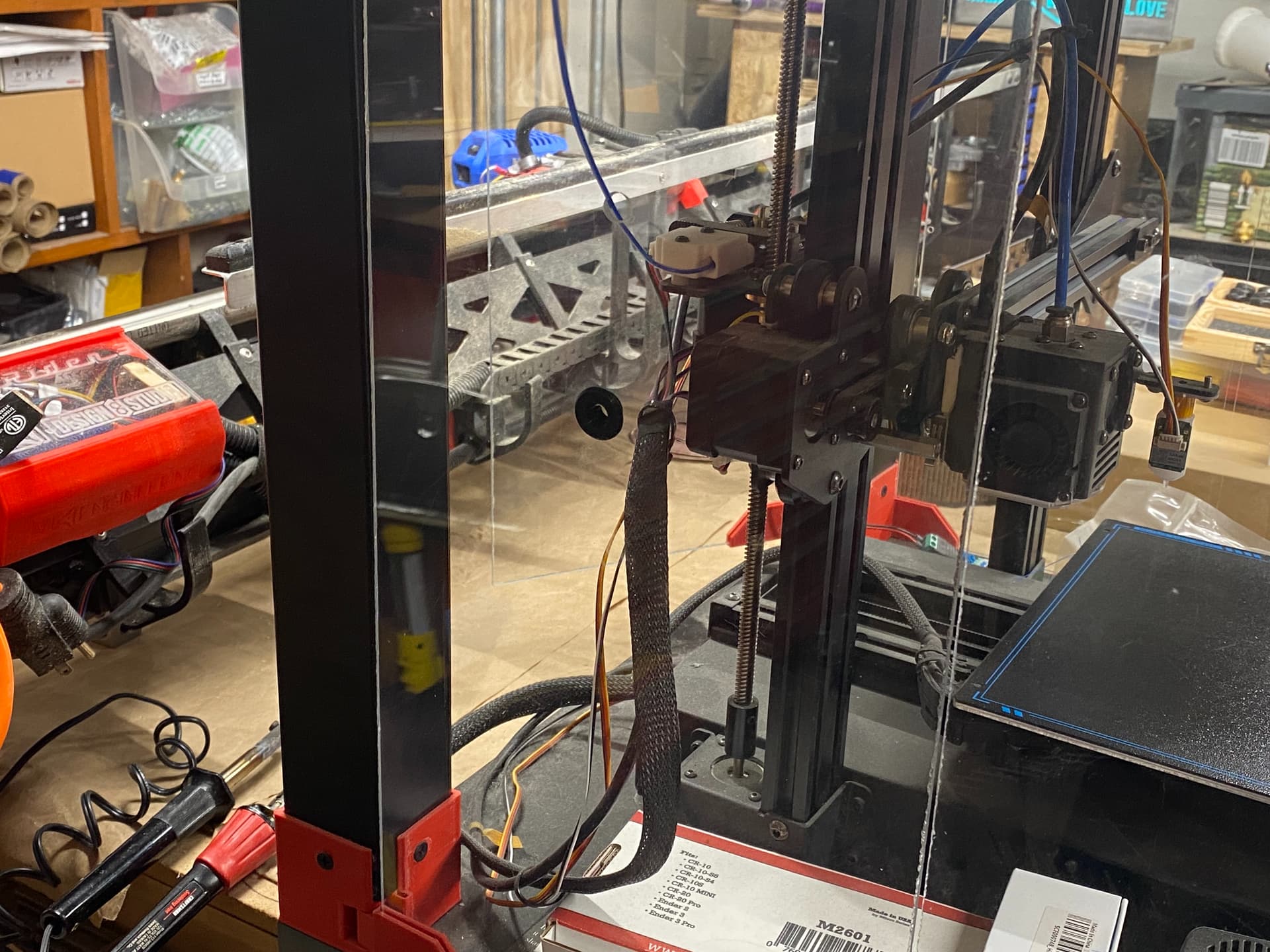
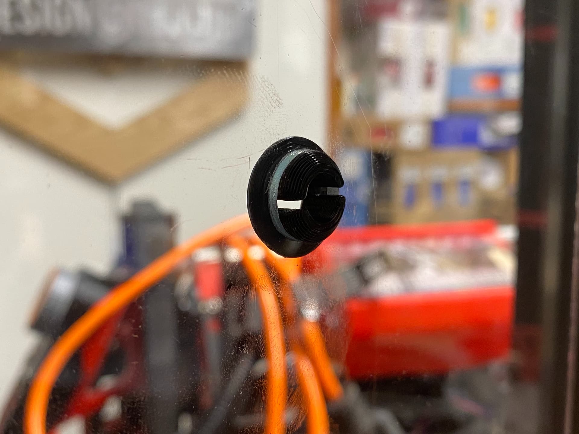
The inlet holes I had drilled were made with a 1/2" drill bit. The printed part was designed to be a cheap, sacrificial thing. It inserts by way of a slight flex (easier done while the printed part is still warm).

The problem with this part… is friction. PLA on PLA friction. It rubs something awful. It makes noise. I don’t like it at all.

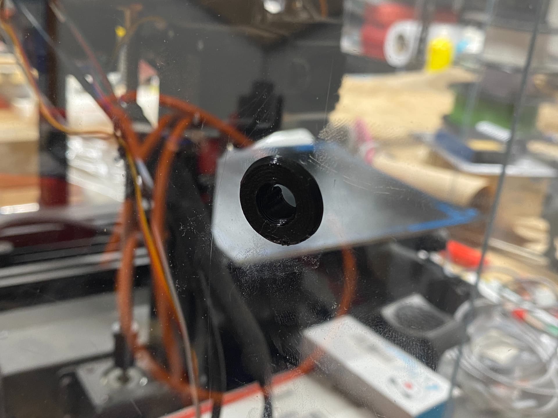
Now, let’s look at what does work.

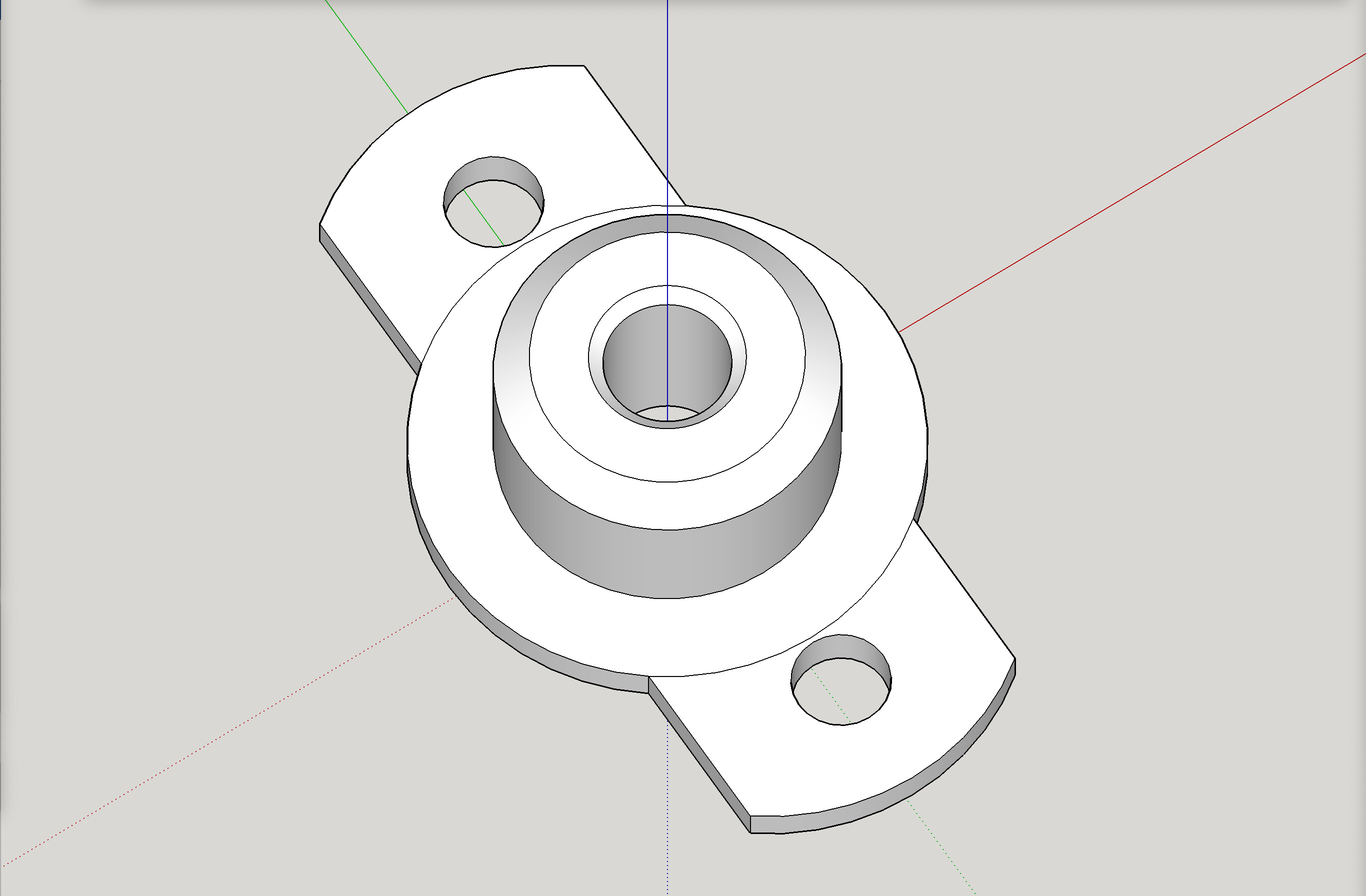
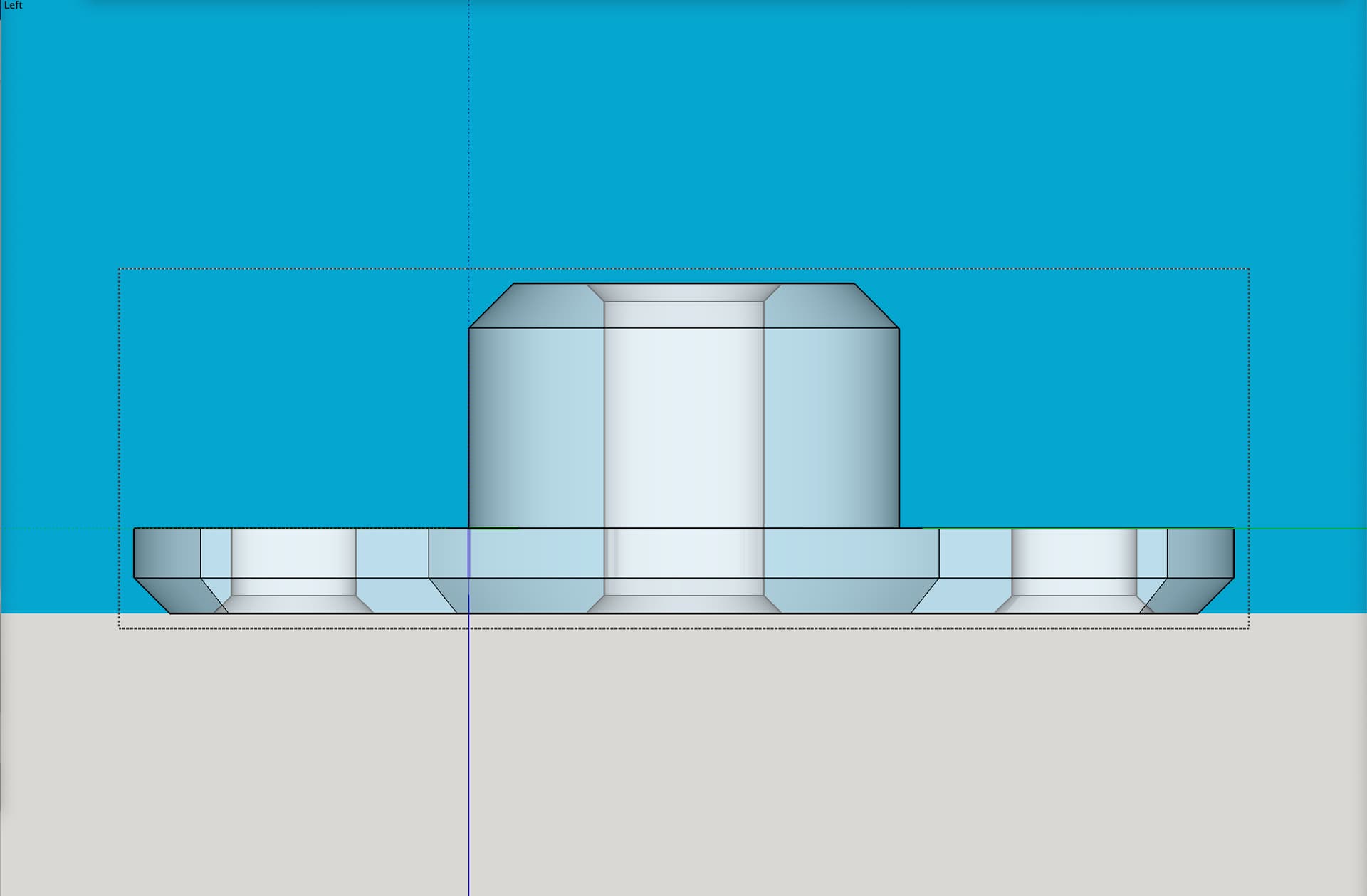
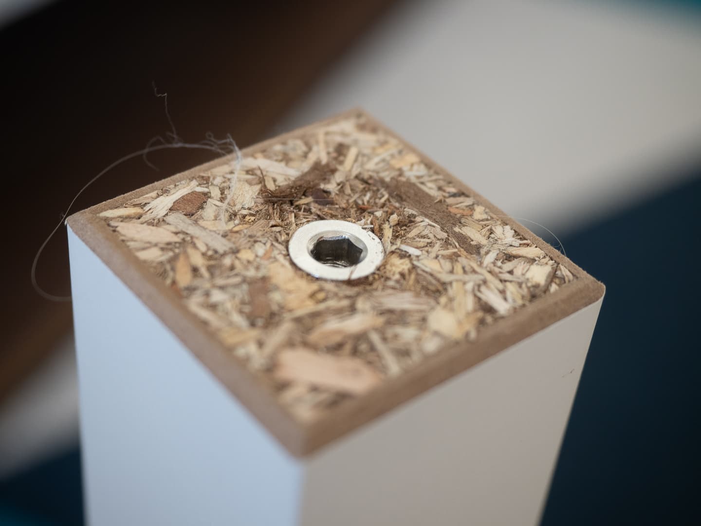
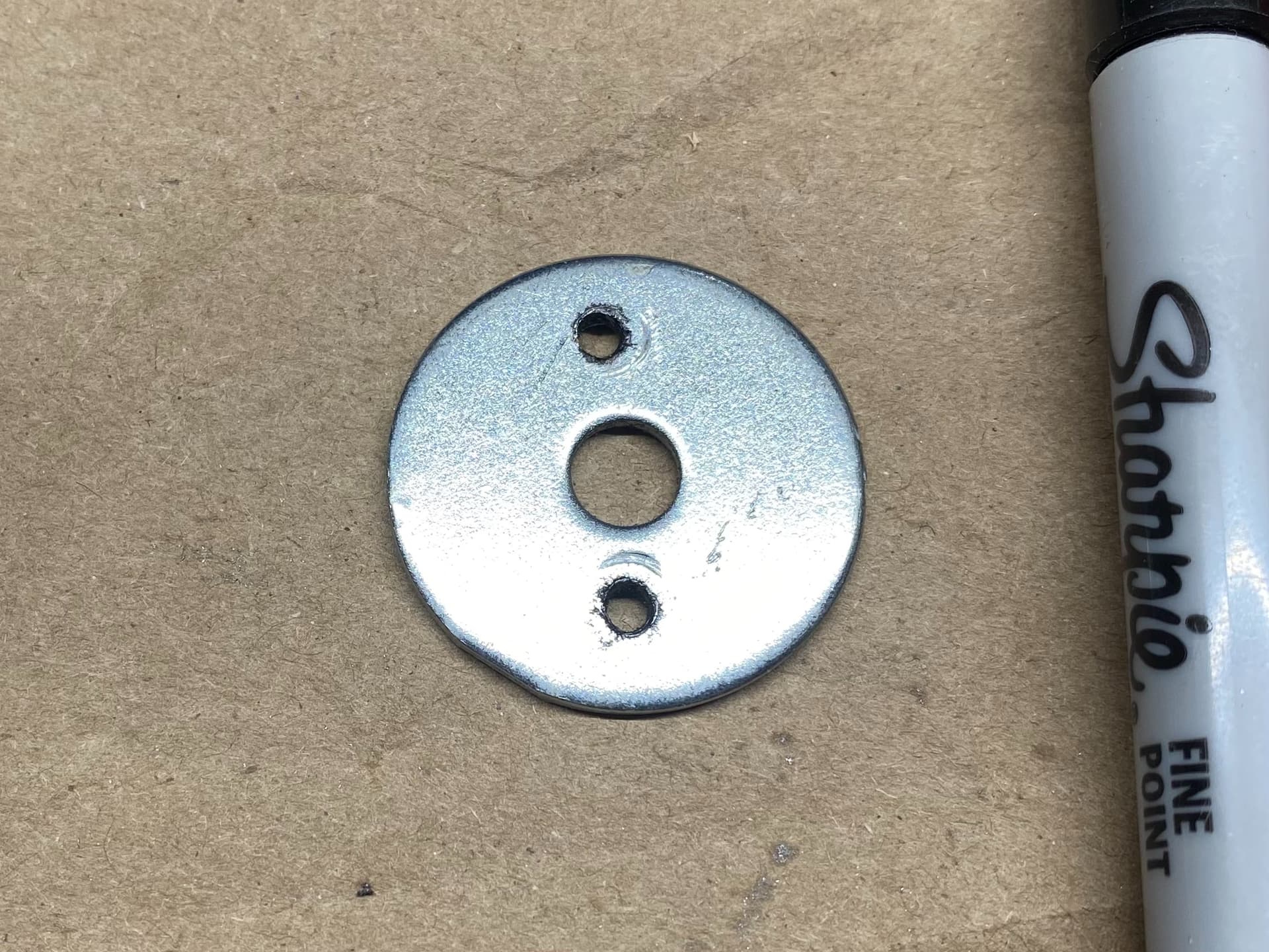
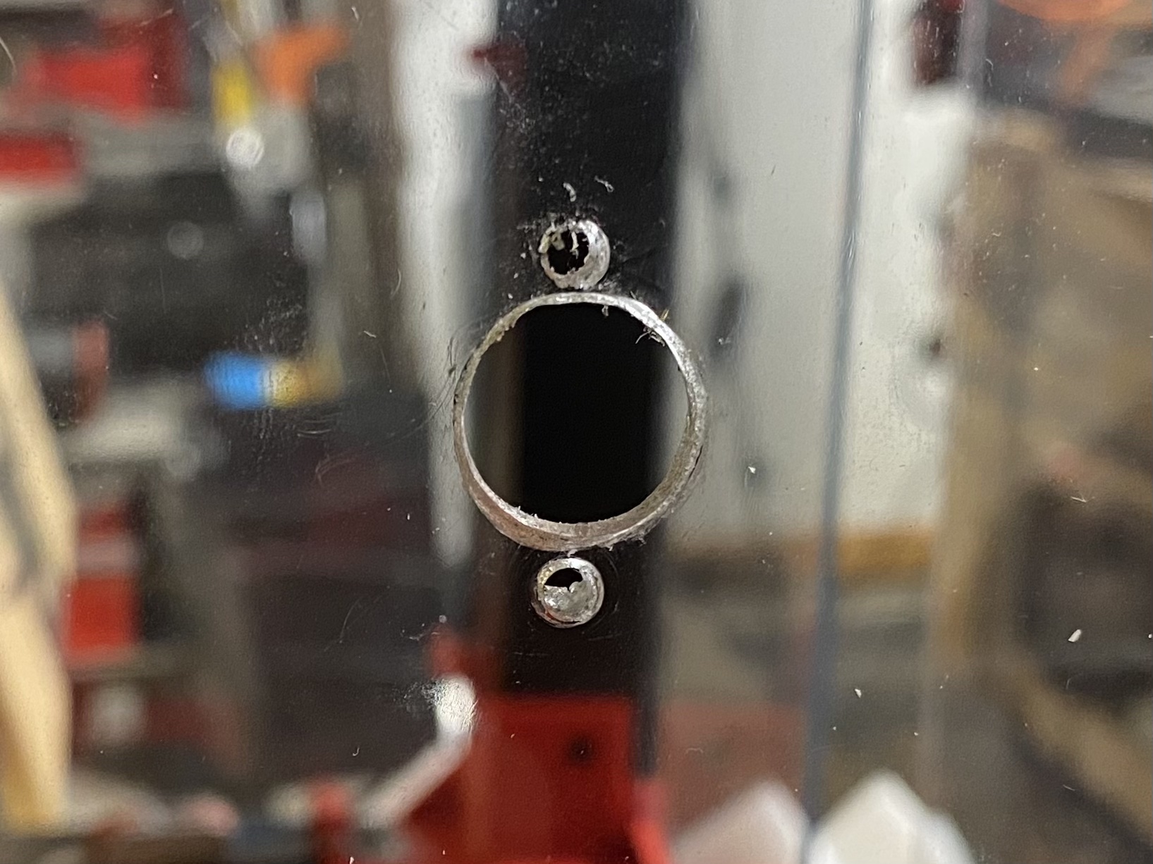
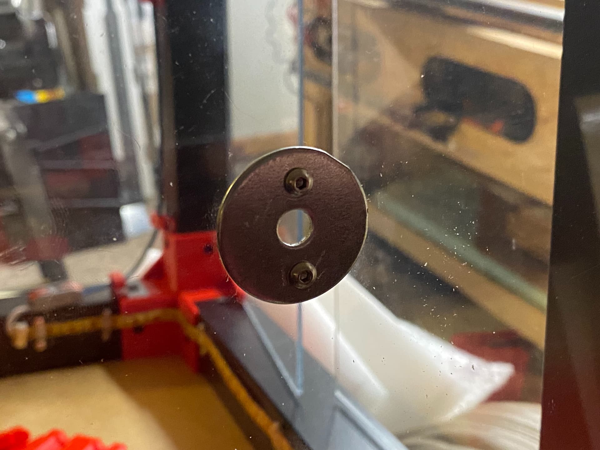
I switched to metal, specifically, a big plate washer:
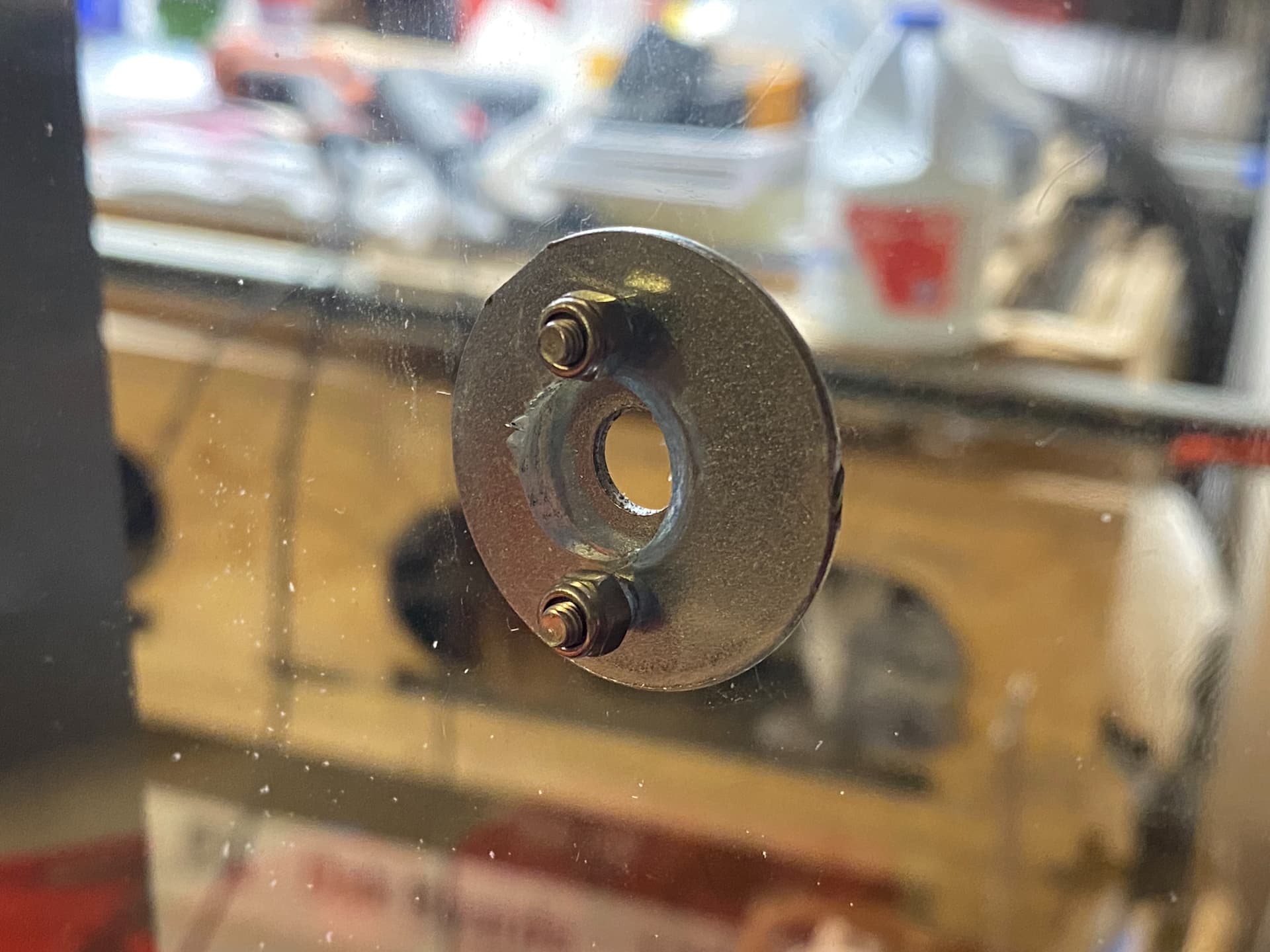


Which led me to…

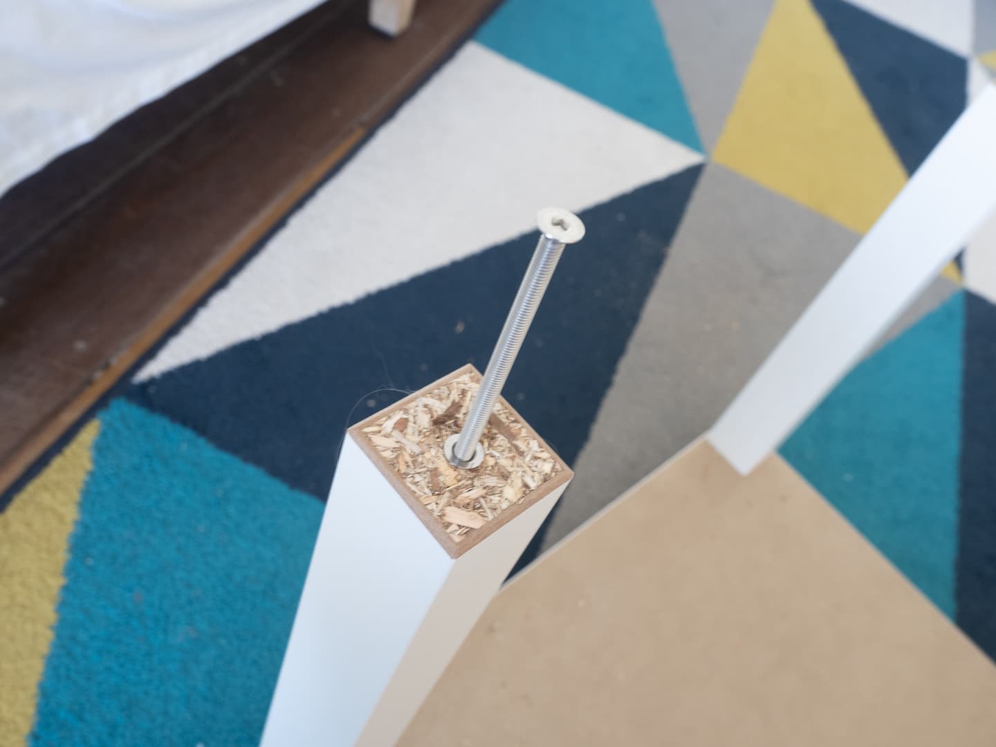
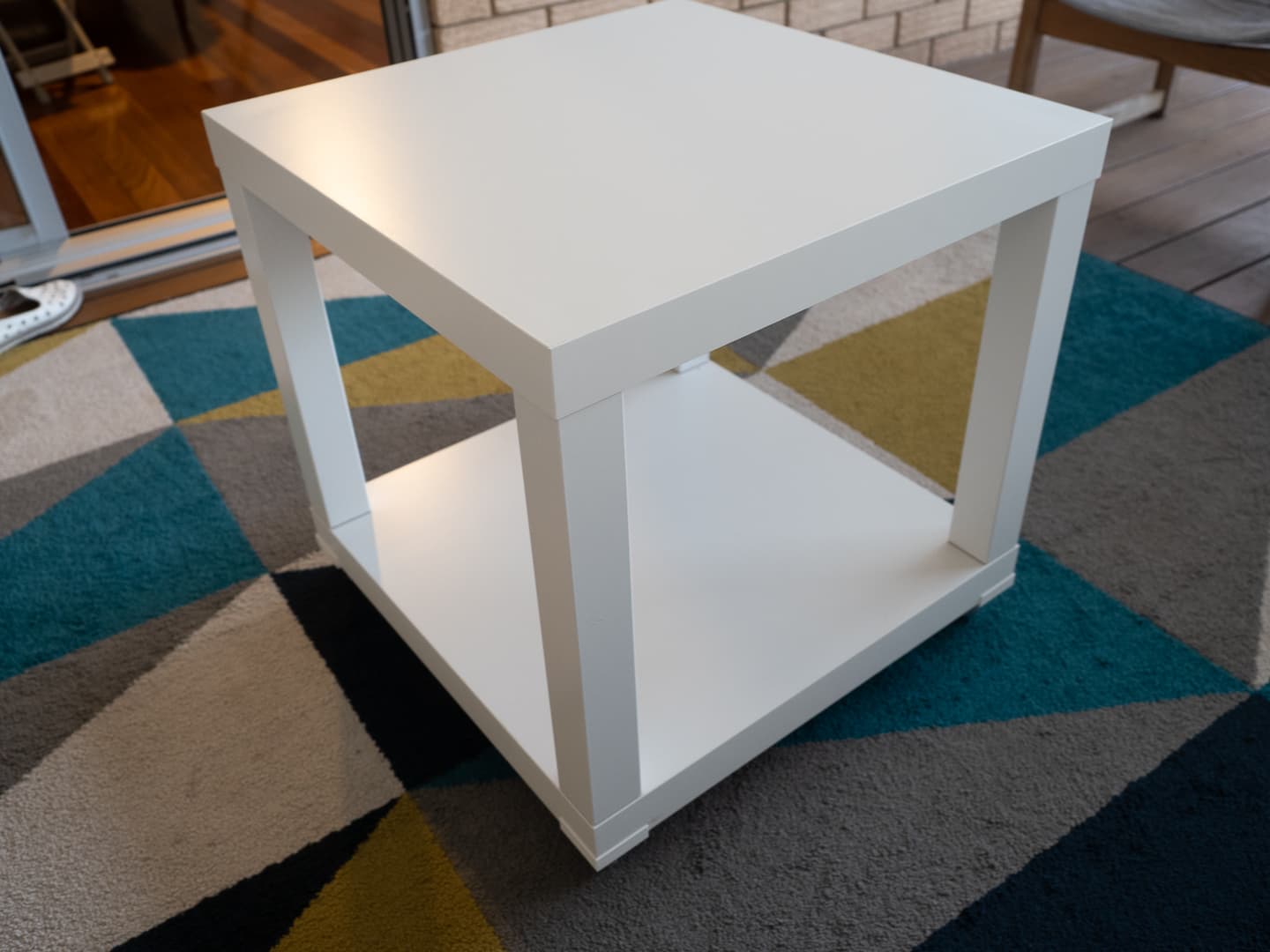
When I started messing around with these enclosures again, it suddenly dawned on me that with the second set of table legs running horizontally at the upper part of the enclosure, just beneath the top, those extra legs would add the needed stability for portability, without the top needing to be attached, and the top could be removable! So, I reworked the enclosure design for a new version 3.

More on that soon.

I highly recommend a reverse Bowden tube here. You will dramatically increase part quality and accuracy and decrease wear and tear on your machine.

Currently, you have an extra load on your extruder depending on what way it is moving. Seems slight but even if your spool is on bearings you are adding way more tension that the previously wires on top link you posted.

1 Like

I guess I could redesign the “Runout Detector Saver v1.0” to have a Bowden tube coupler thing on it…

It doesn’t even have to have the coupler. You get a lot of benefit from just not pulling. pushing is much less of a factor.

1 Like

I don’t know what this means: “previously wires on top link”

My inlet has a 3mm hole on the filament side, and a ~4.5mm hole on the printer side that fits the PTFE reverse bowden tube to my extruder. The incoming filament never touches the printed component, just the PTFE tube. I’ve never had a problem with this.

1 Like

Ah, nice.

Is this a model you’ve shared?

lol. Nope. It’s a pretty simple model. It just needs a 3mm hole for 1-2mm that expands to a 4.5mm hole for another 3-5mm. No clip seems to be necessary for the PTFE side of things, though I did do one that had a 6mm opening, and I used a compression fitting for the PTFE tube. (That’s on the Repeat printer)

1 Like

Thanks. I will probably do something like this!

FilamentGuide.zip (26.8 KB)
I just did one up… The fusion model is even parametric, lol. Don’t know how to share it though

Edit: Actually, if you don’t want the whole reverse bowden tube… You could just use a small chunk of the PTFE tubing, 10mm or so. If you did it that way, I would set it up so that any friction with the filament pulled it into the fitting, so reverse direction.

1 Like

Thanks! For sharing a Fusion model, use “export” and choose the Fusion archive option.

I am already almost done with mine that’s based on your description, but I may go ahead and import yours just to grab the “business end” bits of it.

filamentGuide v1.zip (50.7 KB)
I didn’t put a lot of thought into the parameter names…

1 Like

Thanks!!

Here’s what I have ready to print. It is designed to have a short section of PTFE Bowden tube going through and coming out on both inside and outside (entrance and exit) covering both push and pull regardless of whether it is feed or retraction.

Here’s the STL (and SKP) for the above part:

Filament Inlet Ring for 1:2" hole in 1:8" thick acrylic.zip (614.6 KB)

Any reason a short piece of Bowden tube wouldn’t work at eliminating friction?

See above. :slight_smile:

Haha, you must’ve posted that while I was reading through the thread. You win this time… :grin:

Slight hijack here - I’ve been meaning to finish a how-to that I started four years ago.

The lack will always wobble if you are relying on angles and screws - there’s simply not enough fixing area to brace that way.

I use threaded furniture inserts set into the legs - I made a rigid base using two lack tables and one set of legs - and it’s completely rigid.

The top is removable but the screws go all the way through the plastic and keep it completely tensioned. and rigid. The more tension you can get on the screw the less chance of any wobble developing down the track. Hopefully the pics are self explanatory, but I’ll add brief notes.


Insert ready to go - I use a bolt with a lock nut so I can wind them in using a rachet wrench.


Insert in place. Note it’s got a hex recess so you can use an allen key if you wish, but I get more purchase withe the big wrench!


Screw in place - just checking the thread is OK.


Base - completely rigid - the casters help of course because it’s impossible to put a shear load on it!! :smiley:


Lid lifts off - screws are countersunk into the top - I run filament through a slot in the top, which of course would not work if I stacked two high.

1 Like

This looks great. One thing I’m curious about: the LACK table legs I got, only had much real wood at one end (the end that attached to the table). The other end was either a very thin bit of wood, or thin wood plus some cardboard. Was your’s like that as well?