This one is really worth reading.
I found it VIA Hackaday so I am sure some of you have seen it. CNC Feeds And Speeds, Explained As A First-Timer | Hackaday
This one is really worth reading.
I found it VIA Hackaday so I am sure some of you have seen it. CNC Feeds And Speeds, Explained As A First-Timer | Hackaday
I have always thought of all this as “tradeoffs”. This very clearly shows all the intricate connectivity of the tradeoffs we have when setting up our cuts.
Now I do feel CAM could be much better by incorporating some of this into the paths. We have to do less work for 3D printing but I think those slicers have to do considerably more work.
That’s surprisingly in-depth for a guy’s notes after ONE cut. I wish he’d have addressed (or at least foreshadowed) his notes on chip-thinning in his chart with the radial stepover.
Otherwise, it’s nearly everything I try to address when I respond to folks about feeds and speeds.
One thing I would suggest differently is not starting with the feed rate and backing in to the speed. I’ll grant that it’s not like we have a huge range of speeds to work with and that most wood has a very large ideal range, but the surface speed (rpm x D x pi) can have a lot of impact on finish quality, and I read that tool coating life can be impacted as well. Or maybe it was that coating modified the speed.
The effect of chucking in a 1/4 in tool vs 1/8 inch is noticeable at the extreme ranges, I guess, but mostly it helps thinking about this stuff when moving on to aluminum…which more and more people seem to be doing (congratulations, Ryan!).
Select the RPM based on the tool/material combo, choose your chip load from the ideal range based on your DOC, then RPM x flute count x chip load = feed rate. Correct for chip thinning if the stepover<D/2.
Learning all this absolutely changed the game for me a few years ago. No more guess work for setups, just evaluating how hard I could push my cnc relative to the tool manufacturer’s expectations. I even had a spreadsheet that would calculate everything, including chip thinning, in that order and I could compare variables side by side. Still have it somewhere I think, but fusion 360 lets you punch it all in that way and tells you the outputs, including surface speed
This article or one like it should be required reading for new folks. Maybe somewhere between the crown and first feeds/speeds question.
I’m not sure I like the sole focus on chip load. It matters, but I don’t think it’s the best way to orient for a beginner.
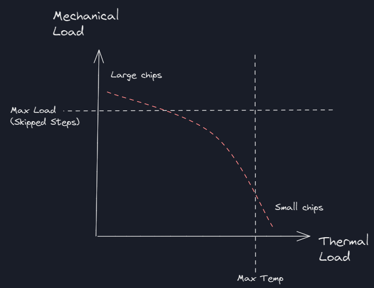
There are more than two dimensions, so simple charts have to leave out some details, but I think this is a good way to orient thinking about feeds and speeds:
There is a max mechanical load where deflection is excessive or steps are skipped, and there is a maximum thermal limit where the workpiece burns or the cutting bits fail.
What is perhaps not intuitive for noobs is that heavier, faster cuts actually run cooler, while lighter, slower cuts are hotter. The line trends down and to the right, not up and to the right. That is key #1 for beginners.
The chip load is perhaps a proxy for where on the curve you’re operating, where a heavier chip load is a faster, cooler cut, and a lighter chip load is a slower, hotter cut.
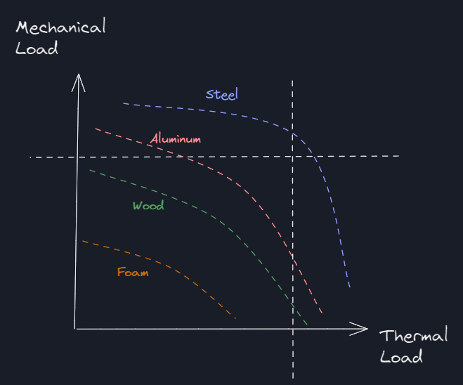
Then for a question of why can’t we cut steel, for example, you might have a picture like this:
If this were true, then there would be no set of speeds and feeds that can succeed with steel. Plowing into the material will cause mechanical failure, and skimming for a long time will burn up the tool. This diagram is pessimistic, and steel has been demonstrated to be possible, but it is helpful for illustrating the concept.
In this figure there is a wide range for wood and a somewhat narrower range for aluminum.
For me this has been a helpful frame for considering all the other variables, like DoC, RPM, # flutes, feed rate, stepover, etc.
It’s also informative for what kinds of workarounds might be possible. Maybe with some coolant, heat is much less of an issue with steel, and slow, light cuts are feasible without having the temperature run away.
I like it.
The calculators are just very inadequate for non-pro machines. So beginners have no where to turn. Even if you did pay for one or use the free one, nothing about it is intuitive. Also, from the other thread, wood is extremely variable.
I have been thinking about how to put together information that might actually help. Something like a minimum and maximum, proven values. I am sure all the regulars around here know how against giving real numbers I was/am, but seeing as how I just made some epiphany’s 8 years later about cutting, I think it is actually needed. As an example, like your graph shows, too slow or thin and aluminum gets hot and work hardens (so minimum chip load), too high of feed rate or too deep of a cut and the machine characteristics get in the way and something breaks.
Chip load is factored in starting at plastic and necessary in metals so that info is actually best with a calculator. In wood it is literally as big as you can get without clogging your cutter. In metals, that also means chip evacuation in things like slots.
Feed rate, limited by the machine but all the current machines should have no issues with any reasonable feedrate. If you are trying to cut at 1000mm/s( or something crazy like that) your other parameters are obviously off.
RPM I see so many people just turning the router all the way up and trying to speed up or slow down the feedrate…exact opposite of what they should be doing.
I just now actually feel like I have failed in this department. I never wanted to show numbers but I know that most people don’t understand there is a minimum chip load . I think it is pretty easy to show some demo’s though and maybe start putting together a guide for various materials. For example using MDF show it burning and then show the make load I can put on the machine, hopefully just changing one parameter. I saw a video the other day of someone trying to take 0.1mm depth of cut in aluminum, at a very low feedrate and high rpm and not understanding why it was not cutting well.
This info could easily be compiled into a chart when we start to get some of it tested and rolling in. I bet we would all learn some things about what that curve actually looks like.
I was/am against actual numbers. The main reason is the variety in the builds and their variety in capability. I want to take a page from reprap and have a page with a bunch of different failure modes, and their possible causes.
Burnt wood: looks like this, smells like this. Possible causes: dull bit, wrong bit, moving too slow, rpms too high. Potential risks: dulls bits quickly (causing more burn). Potential fixes, lower rpms, etc. (But more full sentences, probably)
Other entries would be wandering lines, falling gantries, trapezoids instead of rectangles, ovals instead of circles, random jumps, broken bits, random starting locations…
I don’t want a bunch of scope creep. But having a page like that before you try to hand out any min/max numbers would be very valuable. If you can say, Typical min of X, going lower causes (link to) burning. That would be a pretty useful tool.
I agree with both. I agree the open-ended uncontrolled variable is build quality.
Good generic instructions are applicable to whatever your level of build quality. Given the machine you have (however poorly assembled), do this and watch for that and listen for this sound. Slow down or speed up or try shallower cuts or tighten grub screws or whatever. If you can accomplish your goal, congratulations, you’re done.
But then there is the drag race. A lot of performance might be left on the table.
Build quality might be A+ or it might be C-. An A+ machine can do [these high numbers], while [conservative numbers] should be generally successful even on a C- machine, and if you’re still not seeing success, then go to troubleshooting.
Ryan can’t guarantee that an inexperienced person can achieve an A+ machine, and it’s ok for support to extend only to C- level, at which point the machine can do everything promised. Maybe by luck or maybe by skill, people can achieve B and A machines in which case “overclocked” capabilities are possible but without guarantees.
If numbers are quoted, it’s important that they are qualified with the appropriate context. There is risk that high rates could be misconstrued as standard, out of the box expectations, and that could be a serious problem if it produces big disappointment and loud complaints.
Ohhhh, that is cool.
It’s not just the chipload to consider, too. There is MRR. All other things equal (which never are), a deeper cut is more…efficient? I know that’s not the right term, but it’s the first one that comes to mind.
I want to push back a little on just turning the router up, too. Rpm*bit circumference is the surface speed. This is usually dictated by the the combination of stock material, endmill material, the endmill coating (or lack of) and affects (but doesn’t control) things like heat and surface quality. Most of us are using uncoated carbide of a small diameter (because they have become ubiquitous and cheap) and we’re cutting wood, mdf, and aluminum. The upper limit for those surface speeds are WAY above what we can achieve with these router/tool combinations. So maybe it’s not the RIGHT way to do it, but I don’t think there is any functional difference between the right way and this way MOST of the time.
Hard plastics like acrylic make it a little more obvious for me. Assuming I keep the chipload consistent by increasing feed with rpms, the chips are LESS stuck together at 20000rpms than 16000. Higher than 20000 and cut quality degrades as I start to get some chipping.
I don’t have any real experience with soft plastics, but my guess is that this is the place where that starts to break down and clogging becomes the main danger.
Honestly, that is the bottom line, right. When you factor everything in MRR and surface finish are all you care about.
I will definitely be doing more testing. I have just been doing the lowest possible RPM to get the best surface finish and keep the heat down (biggest bite). Don’t forget I have a mist system and that is so easy it is cheating in aluminum with IPA. I am just pushing regular cutting at this point.
I have not cut much plastic other than HDPE.
closing old topic to help fight spambots