[probe]
pin: !PG8 ;enable internal pullup resistor as this is an NC switch use ! to invert if needed
x_offset: 0
y_offset: 0
z_offset: 0.5      ; plate thickness in mm
speed: 5           ; probing speed of 5mm/second ideal is <10mm/sec
samples: 1         ; number of probes to perform per sample

[gcode_macro PROBE_Z]
gcode:
  M117 "Probing"
  PROBE
  SET_KINEMATIC_POSITION Z=0.5
  G0 Z10
The three back ticks on the phone was making dropdown lists instead of a code window, changed to pc to edit code windows.
I too have been fighting the ghosts in the machine. Even with the proper tools and supplies, my wire terminations have been problematic. Unfortunately not yet fully resolved.
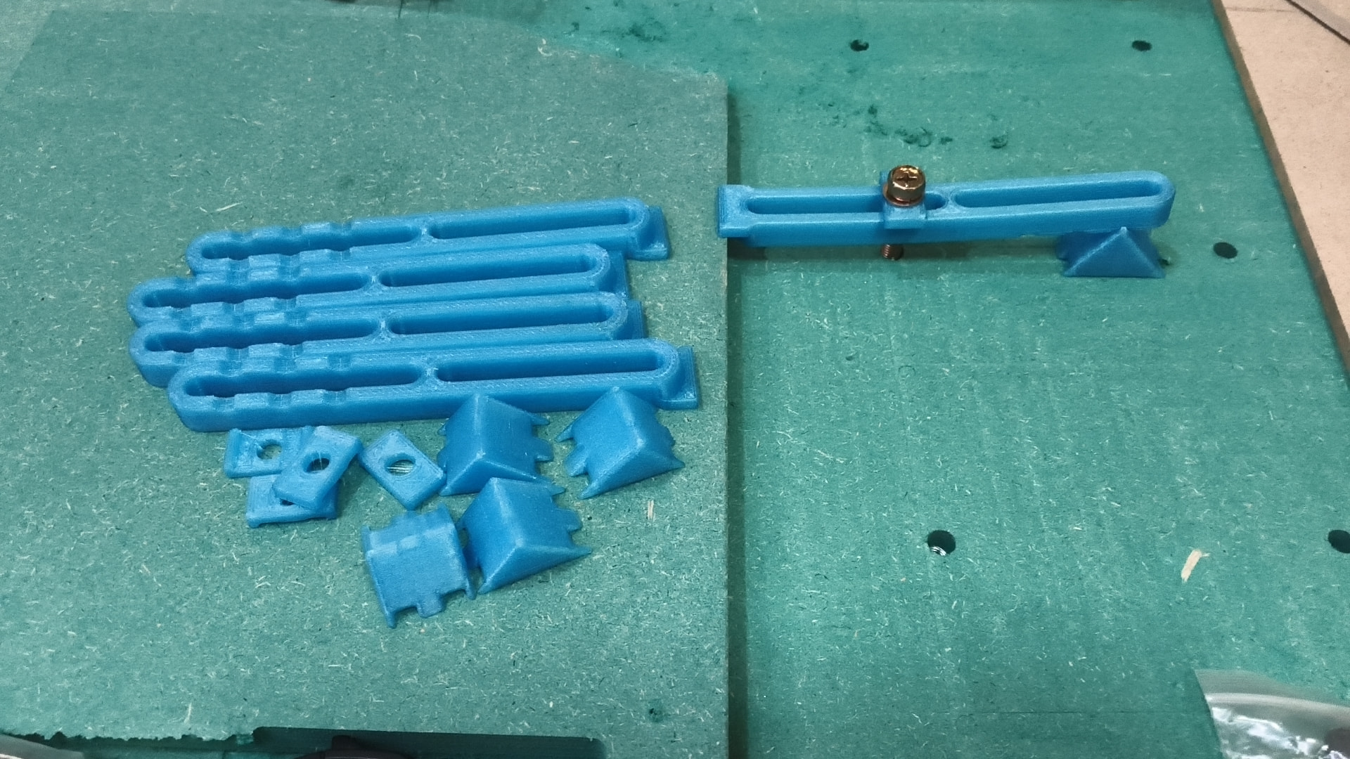
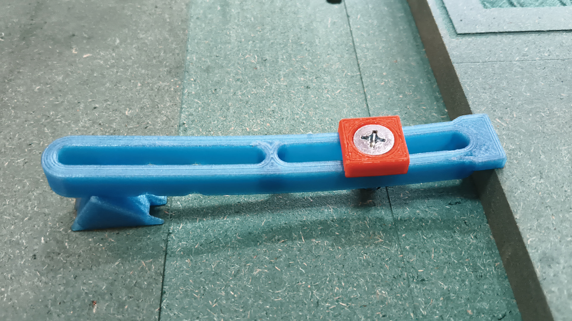
Have designed and printer some hold down fixtures.
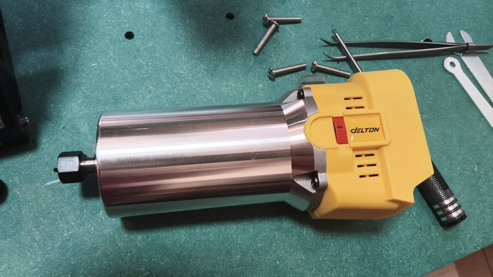
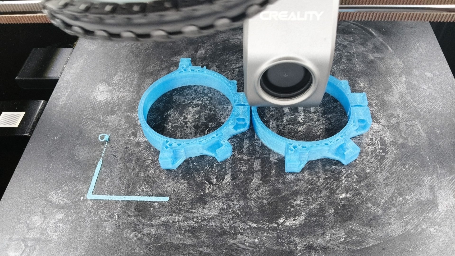
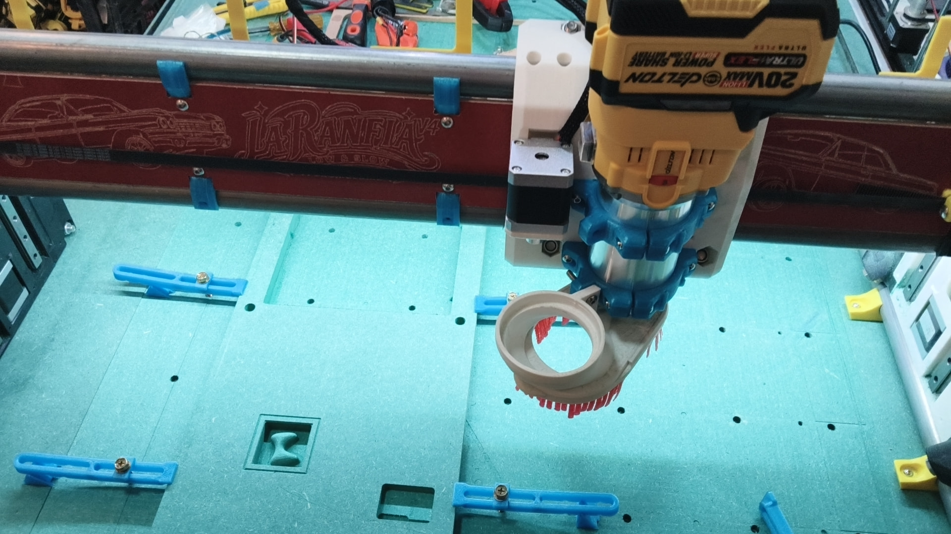
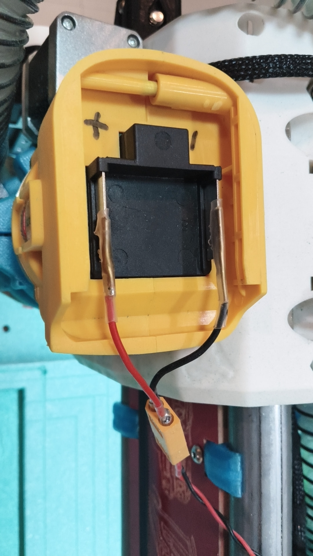
Went on a bit of a tool buying spree… sick of not having the tools I’ve had in the past so I “invested” in a no name chineese brand. Skill saw hammer drill oscillating saw Angle grinder A little blower vacuum gizmo and last but maybe most importantly a brushless 20 Volt trim router. When I discovered the trim router I started doing some research and come across a project called Mod Kita where they’re powering the Makita version of this similar set directly with a power supply and optionally running it off of a dedicated full telemetry feedback speed control. I’m just now printing some clamps for it as it’s 1mm smaller than the Makita. Maybe a total bust but it’s an interesting investigation. It certainly runs quieter and should be more efficient and hopefully cooler than my generic 220 Volt router.
I posted some updates on what I’m calling mainsail CNC pendant in the software section. It’s actually coming together quite nicely and it’s pretty exciting that able to recover some of the limitations from fusions hobbyist license.
Unfortunately my spindles been pretty much idle since the last update. Still Want to get a Cabinet together and I’m still waiting on dust collection hose.
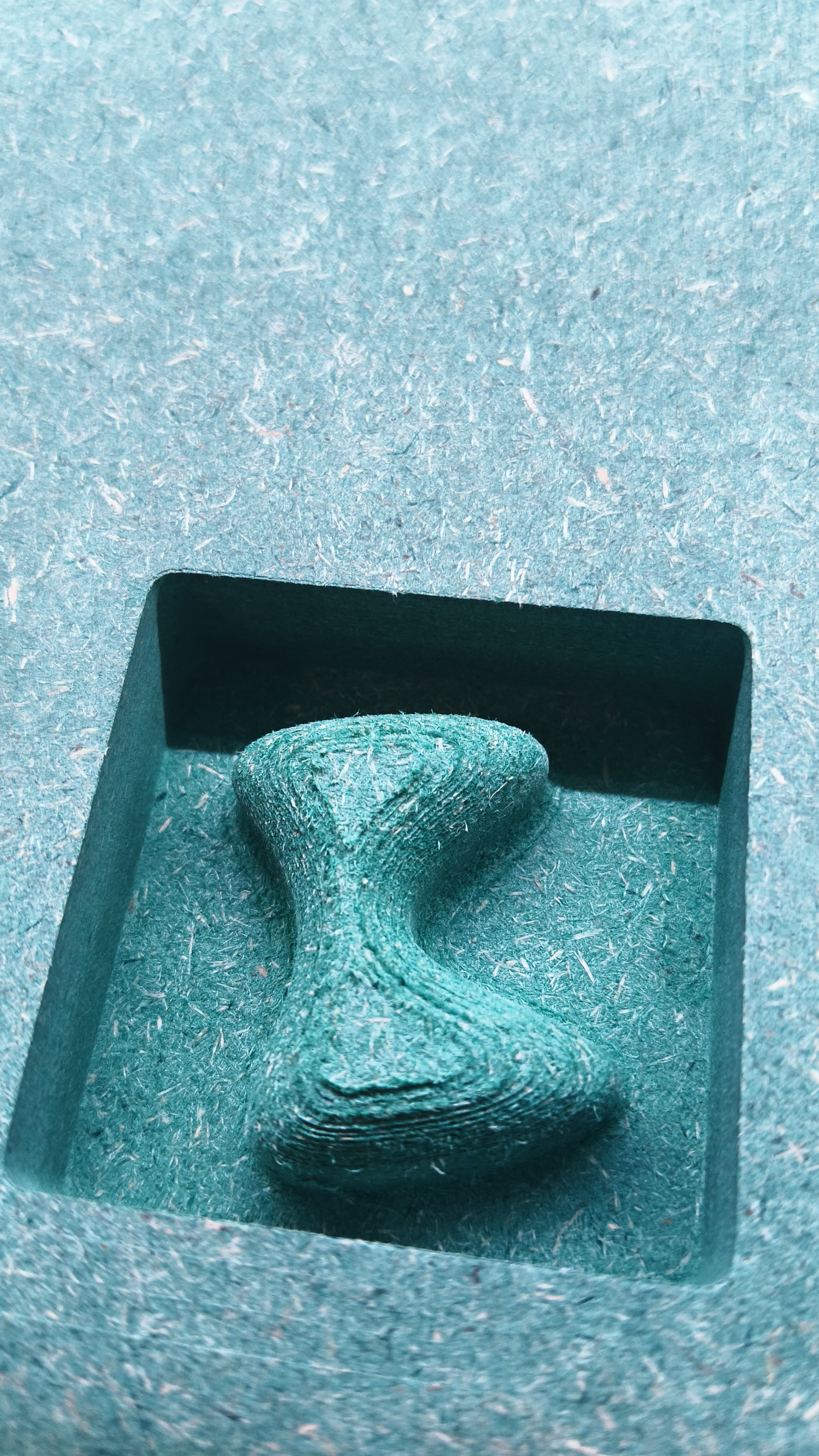
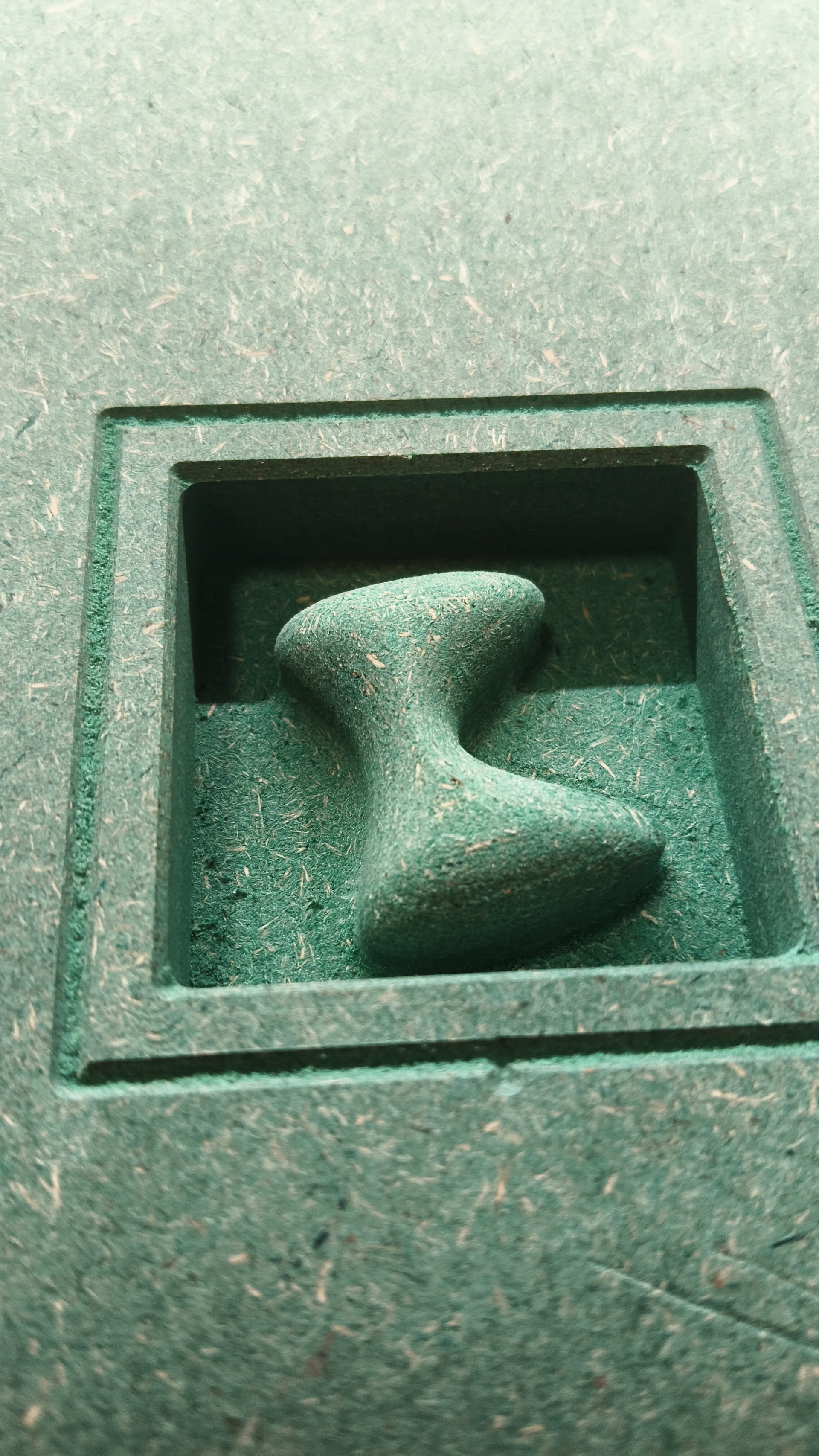
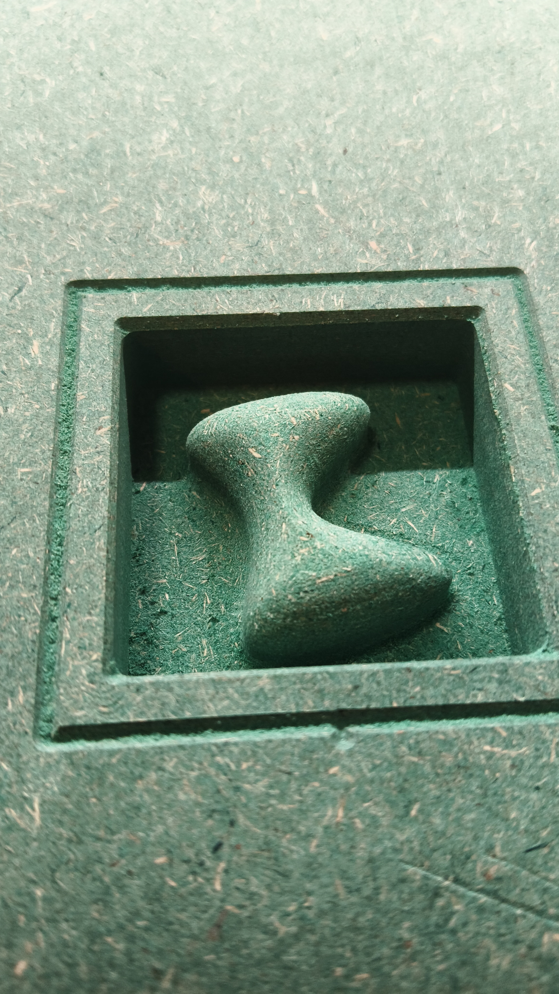
Can’t sleep with a new router on the machine… this was a program I set up to challenge myself to figure out how to effectively machine it infusion. The bottom radius is a variable radius and parts of it are smaller than 8th inch so the 8th inch ball mill can’t cut all the fillet and had to go back and clean them up with my 8th inch end. Unfortunately the moron running the machine managed to hit E stop changing back to the 8th inch end mill for the final profile cut. Made it through the first 2 tool changes. The router works awesome! so much quieter. Seem to have plenty of power similar to what the other one has and I think the speed control is actually regulating RPM so it doesn’t really load up the router just adapts and puts more power to the project.
After the 1/8ball and chamfer bit right where I hit the estop swapping back to the 1/8 single. I knew this was gonna be a problem I do need to get a mechanical E stop switch in place. It’s just too easy to hit it on the phone and obviously you need to be able to use it when you need it.
They say life is about learning… Tonight’s lessons:
Don’t run WD40 through a shop vac in the spare room and expect the one whom must be obeyed to be pleased with the bouquet!
Don’t think the .5mm depth of cut that seemed too easy to mean the 2mm will be too!
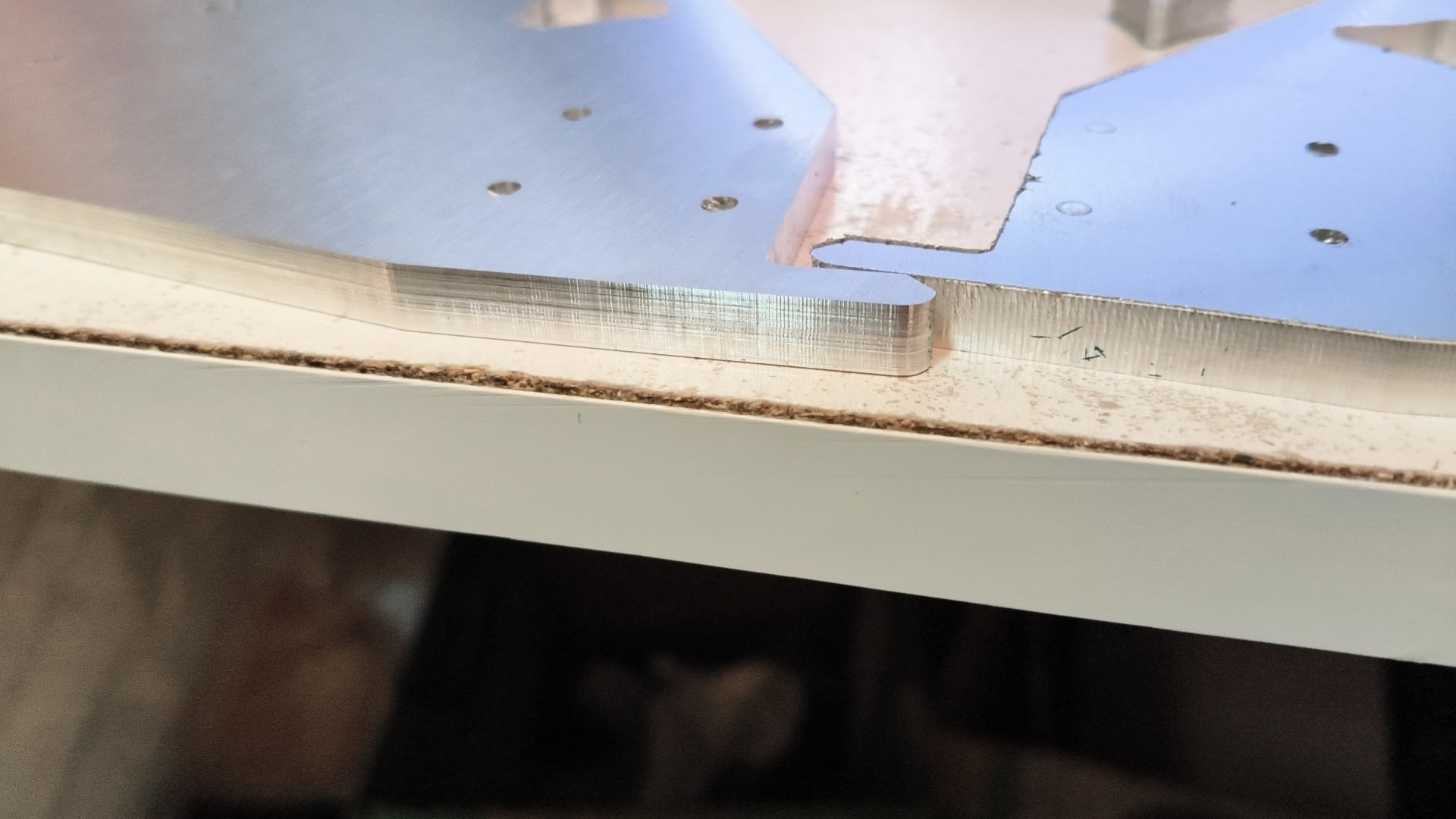
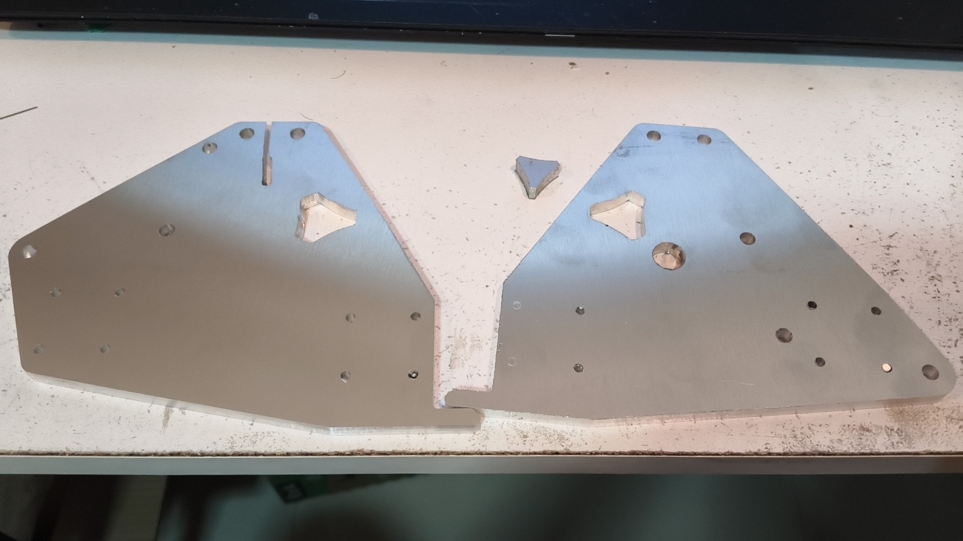
Not super happy but the XZ plates are ready to deburring and install. Cut everything but the small belt slot with a 2.5 single flute upcut and the belt slot with a 1.5. Managed to break a 2.5 on the aggressive depth of cut but Post mortem indicated it was a lack of lubrication as there was aluminum gummed up in the remains of the bit. Otherwise things want pretty painlessly. The 3.5mm holes are snug on a 3.125(1/8") drill bit so everything might be a bit oversized. Didn’t do any testing so my bad!
I sorta was thinking the surface finish looks a chattered mess LOL…
IPA will be explored. The brushless router is nearly ignition safe, the shop vac, not so much!
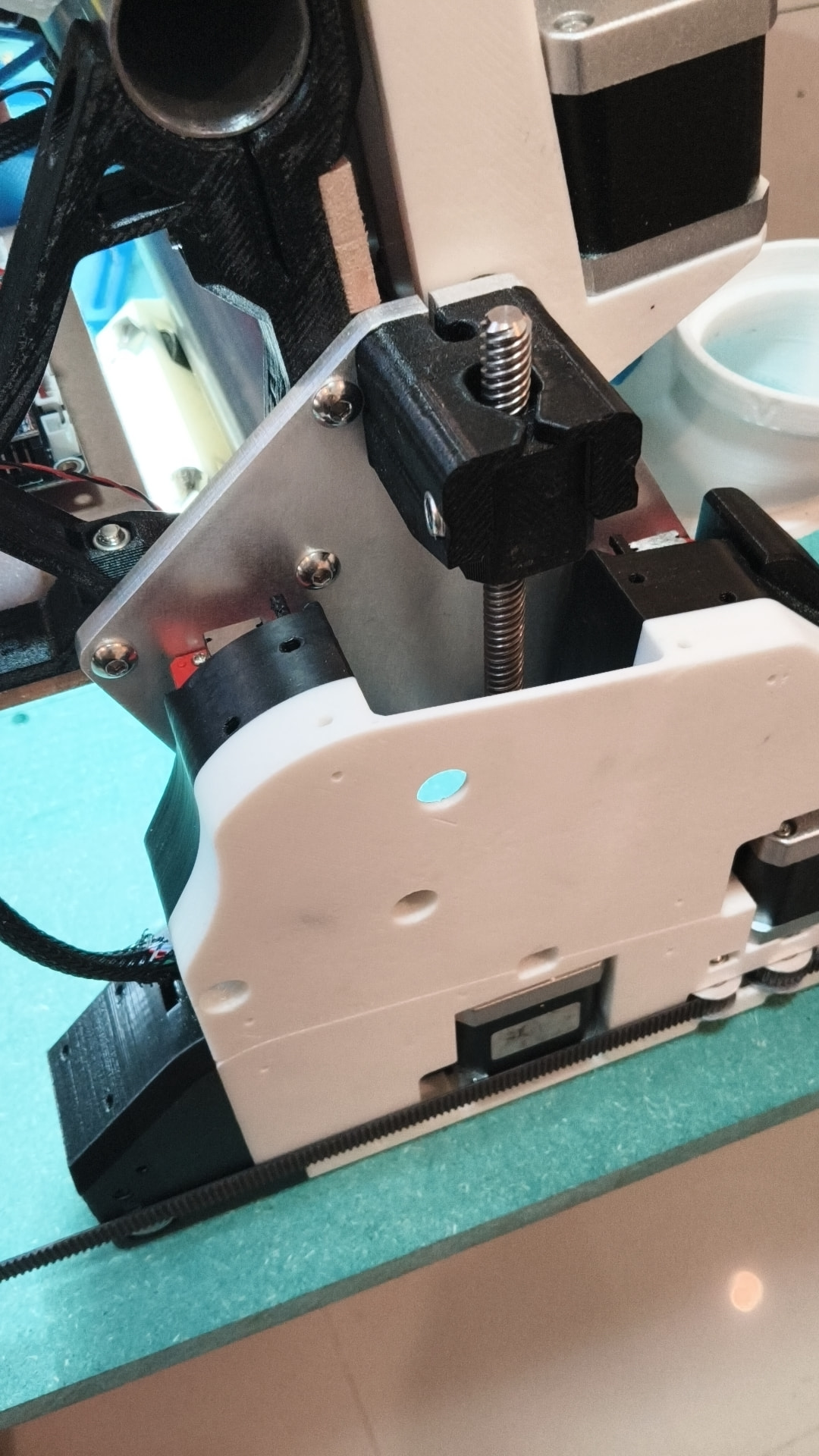
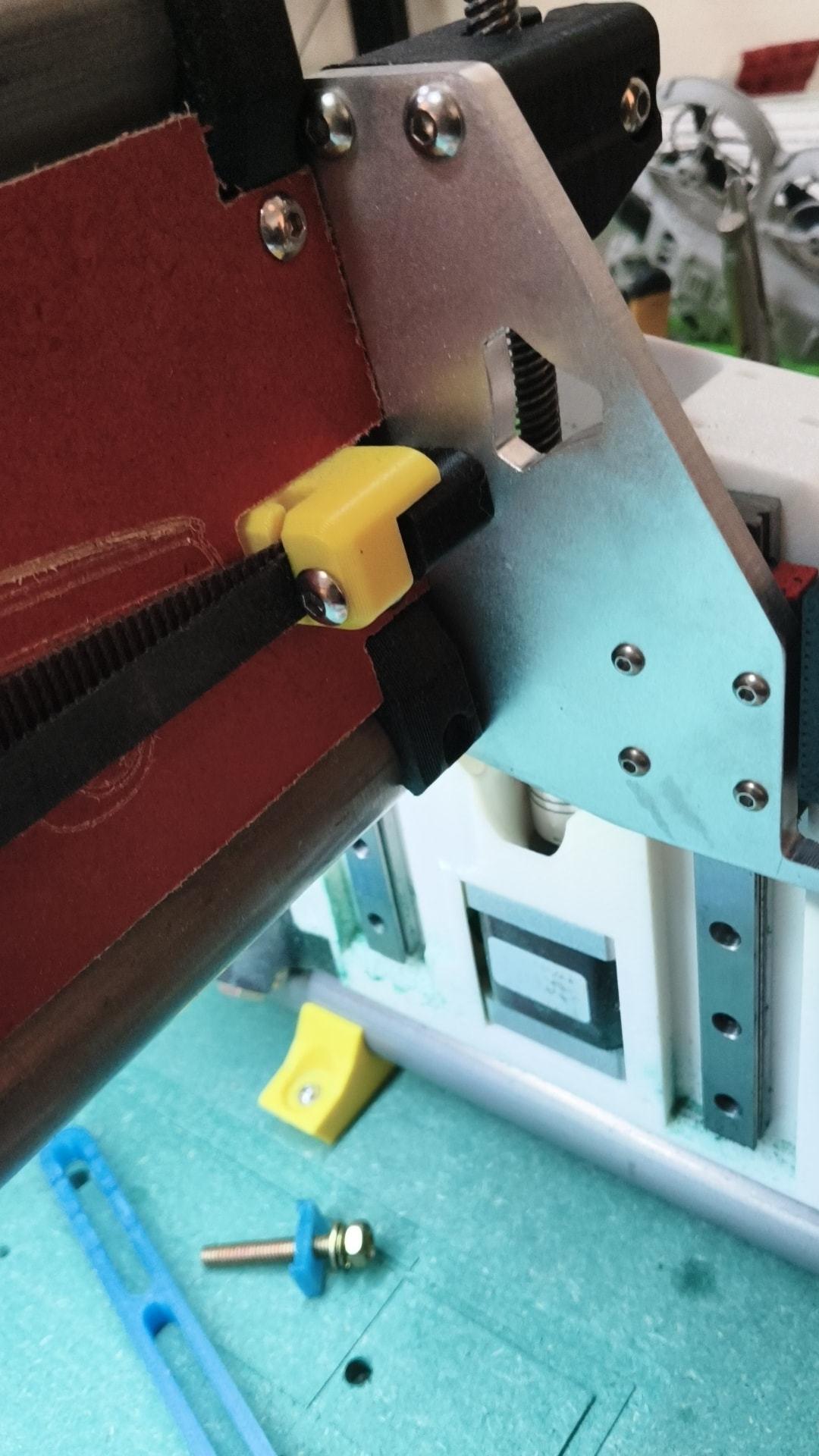
The XZ plates are fitted and LowRider appears pleased. Gave them a quick burnish with 240 in an orbital cause that’s what was handy! Did notice the cuts have significant taper. I’ve never tried to push a 2.5mm bit that hard. Amazingly consistent and the tool lived thru the deflection. Interesting.
The aluminum made a huge improvement in rigidity! The PETG plates were bow legged. My Xmin Y belt limit switch barely makes contact now as the machine is now vertical with the Y axis where it belongs. Makes me want to try another aluminum cut to see the difference but don’t feel like dealing with more alum chips ATM!
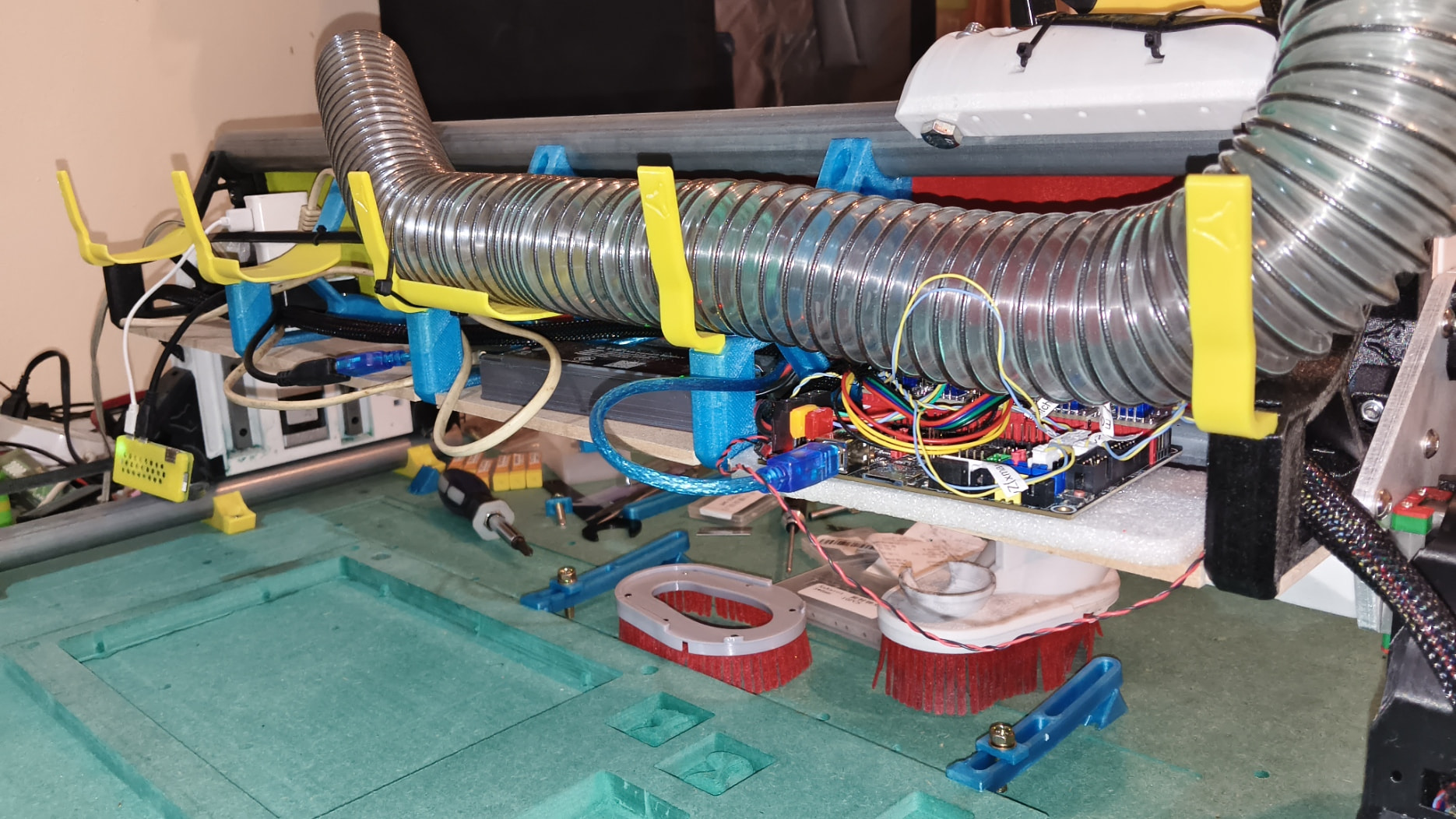
Cleaned up wiring a bit while apart. Still need to secure the electronics and am still waiting on dust hose. Ordered a 90deg USB B cable to shrink the SKR footprint. Baby steps but it’s blossoming into a quite capable tool!
Huge thank you Ryan, I hope you enjoy the success of this project!
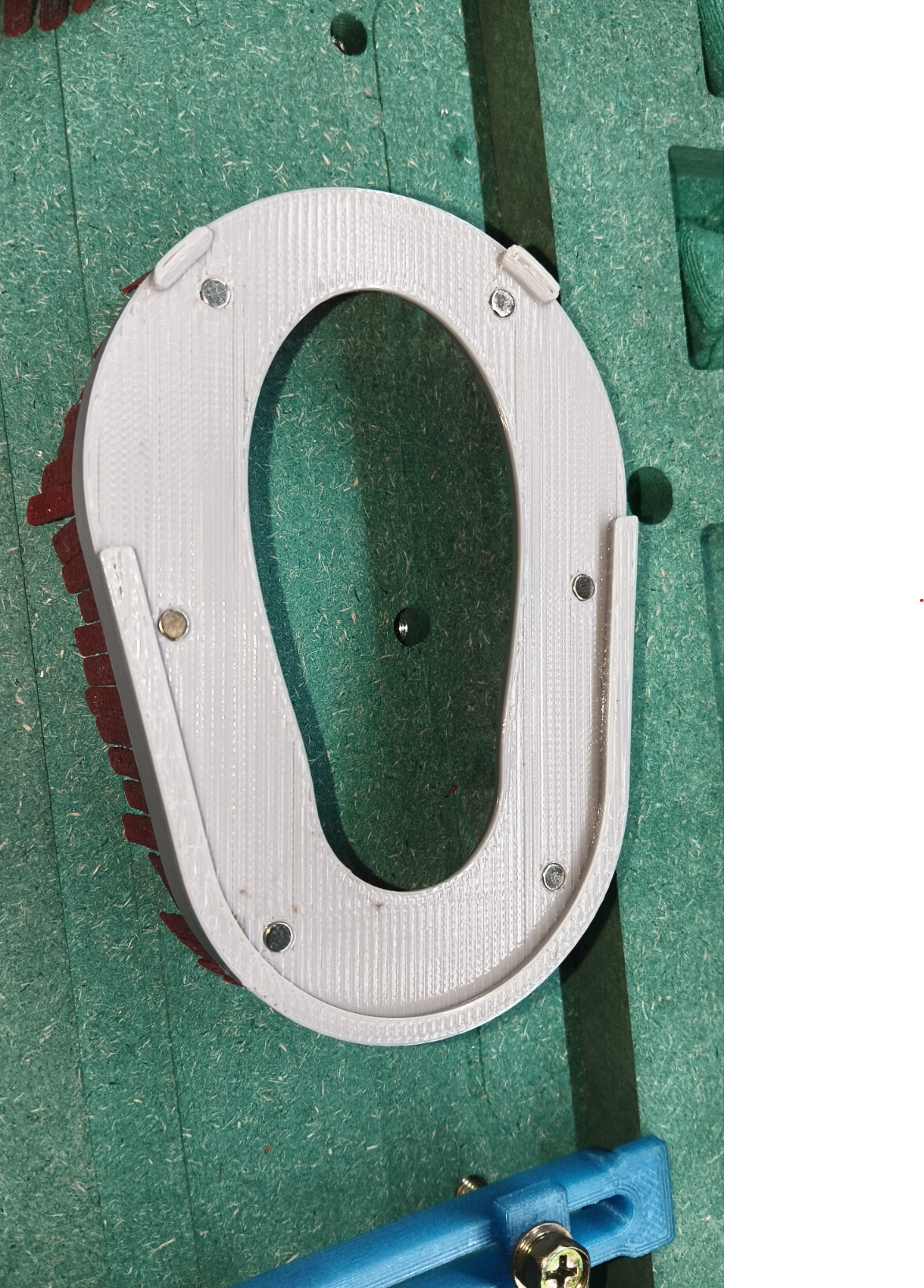
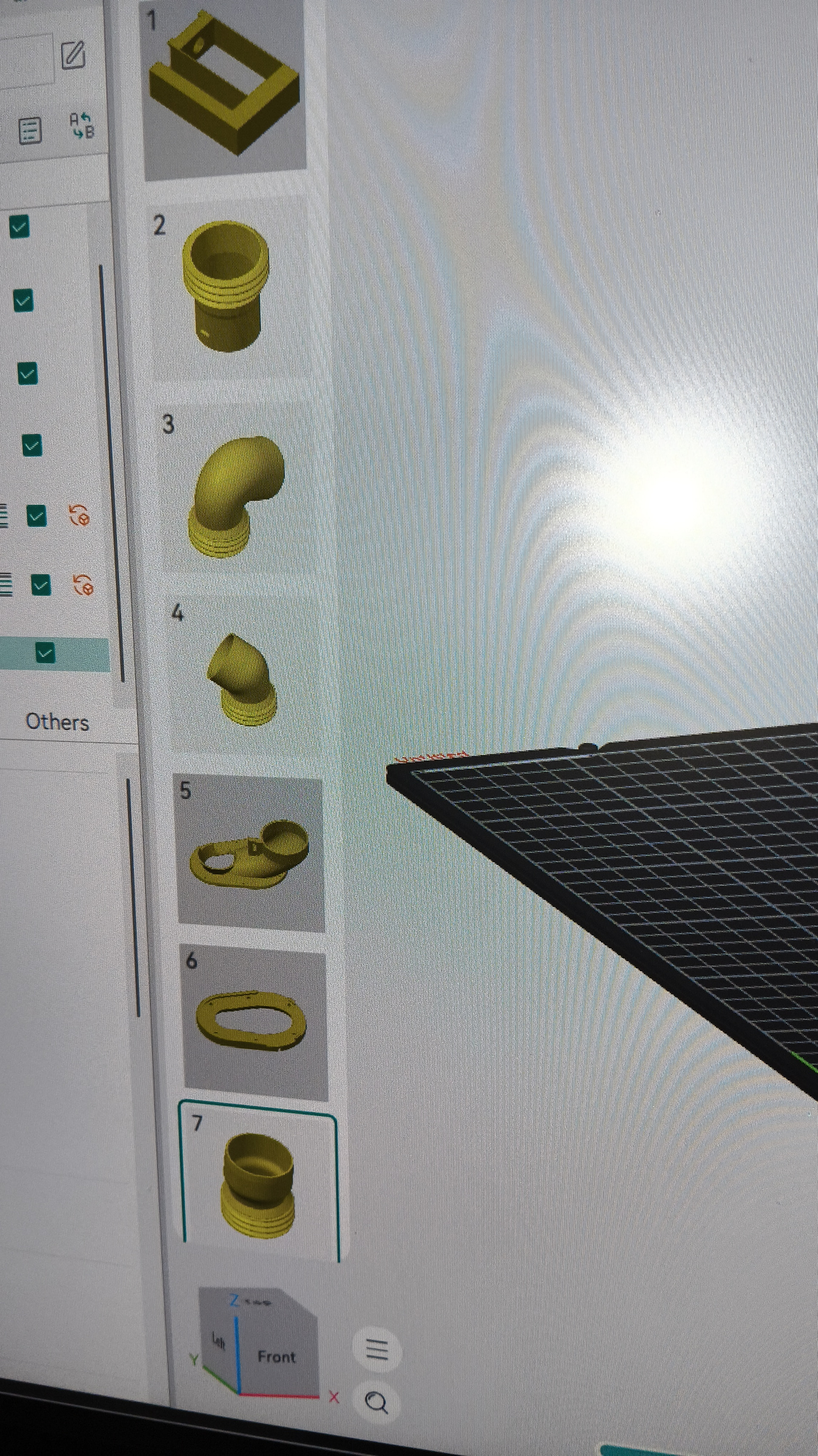
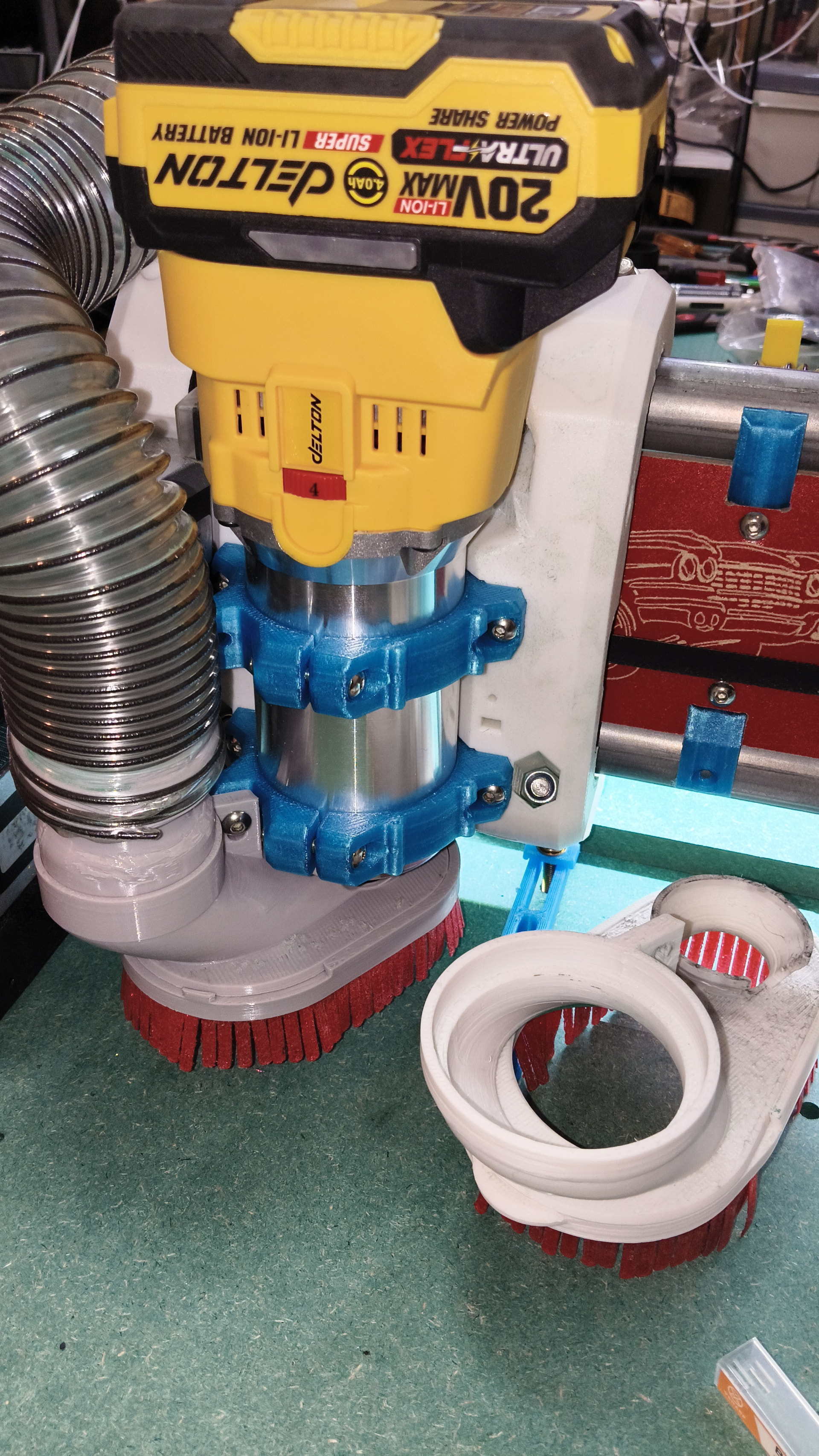
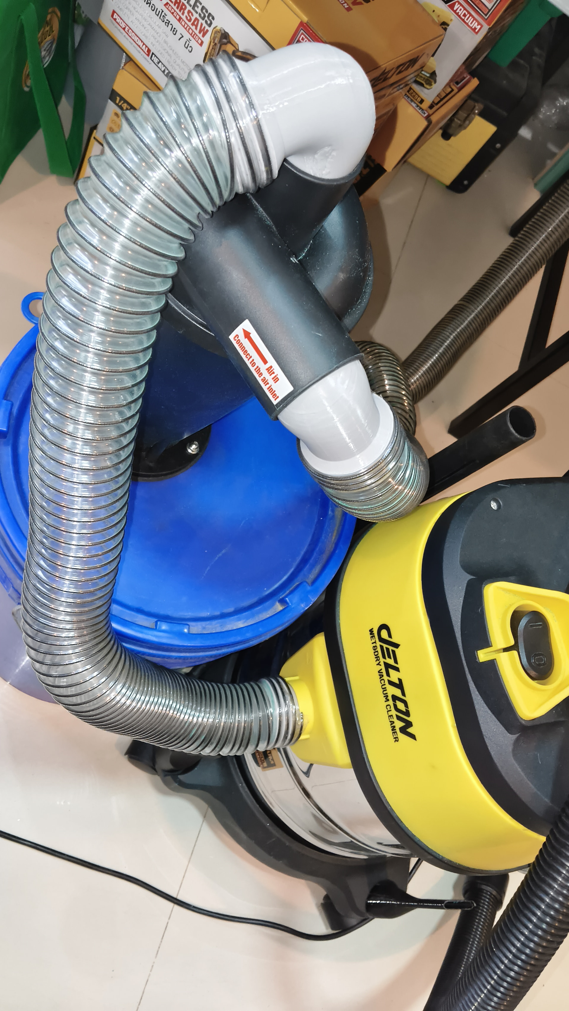
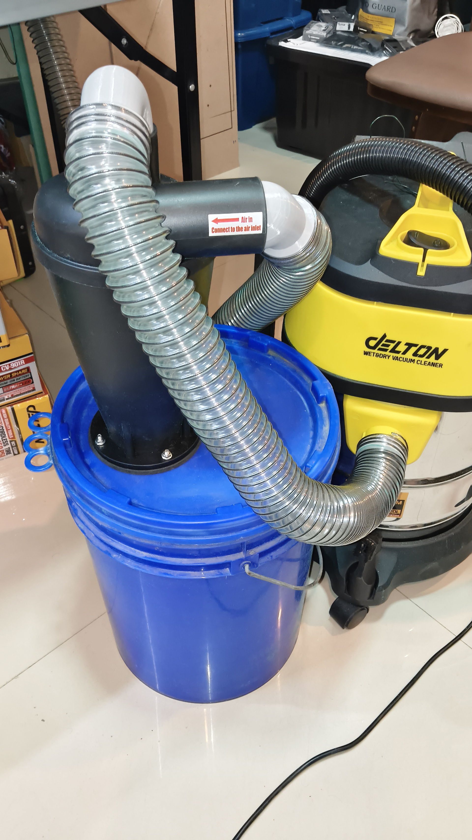
Worked a bit on a pen tool changer yesterday and my long lost dust collection hose arrived. That sort of changed plans so today I designed and printed a bunch of parts. Running 2" hose so I revised the shoe & made an adapter for the hose ends including a pair for a cyclone separator. Did add six magnet pairs holding the shoe on in addition to the mechanical latch.
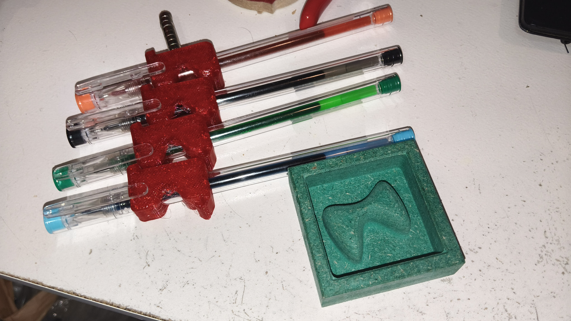
The little green block is my little test I made to work on learning Fusion 360 Manufacturing Strategies. It’s actually taught me a lot. The fillet at the base of the feature is a tight, variable radius it’s tighter than any tools I have so I’ve had figure out how to machine it with a 1/8 end mill.
I’ve changed my router brackets for my smaller diameter router and in doing so I change the mounting pattern for accessories. Planning on coming up some kind of kinetic mount maybe with the central bolt for heavier applications. That’s where the pen changer project stalled yesterday. Intend to use an RC servo for pen lift as it’s quick, easy and should save my Z lead screws some wear.
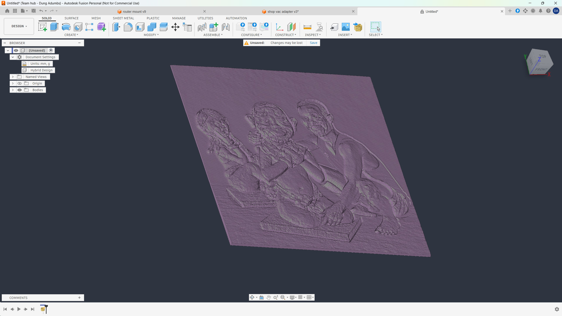
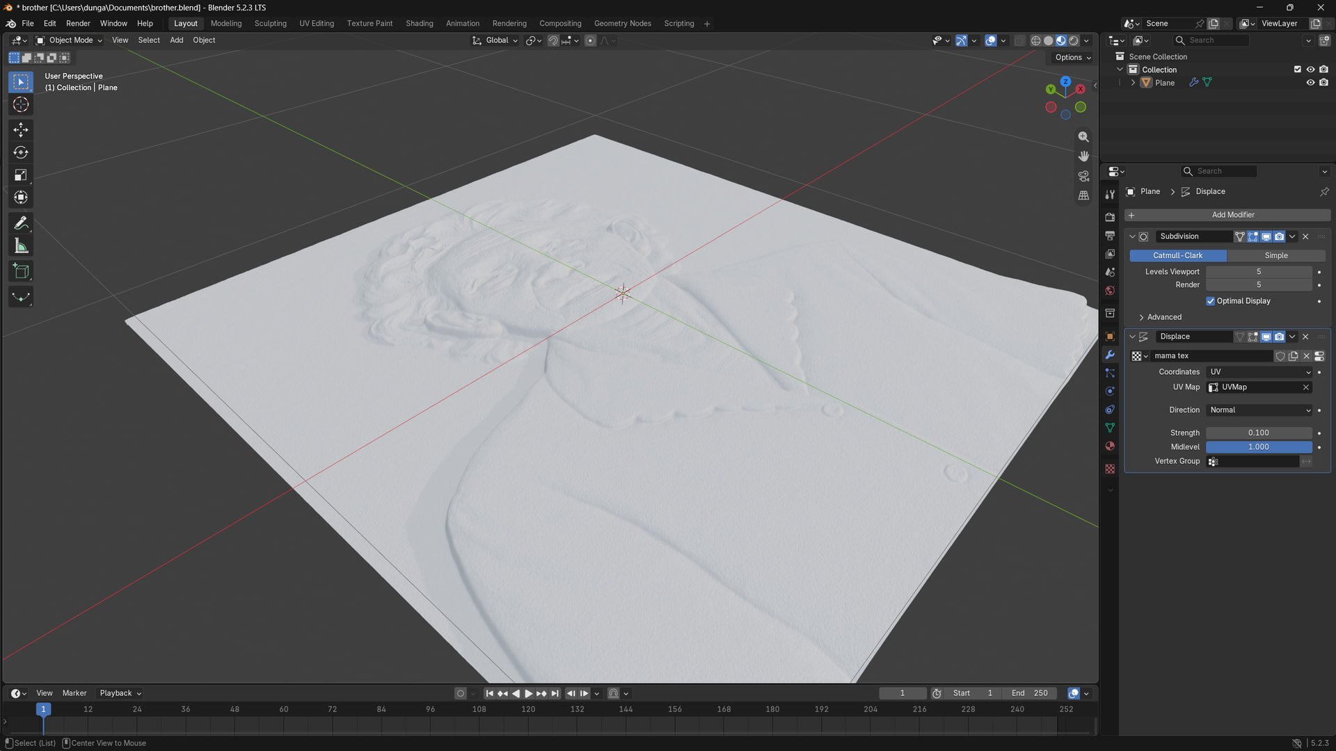
Have also been trying to find an efficient method to generate 3d reliefs from photos. I haven’t looked at Blender in years and I remember why I Stop trying before. Thank God for AI. Anybody has any advice i’m all ears
You’re absolutely correct! I had recollection of this grounding need as I installed everything but the better part of excitement got me and I started my first cut. During the cut I noticed a small shock at the router when I was messing with the hose end. And the cut failed the, Y axis went out of sync for the first time. I had not put two and two together again yet until you posted.
Being in the third world I’m not sure I have access to a proper earth ground in the house. I guess we will find out. After seeing your first post before I went to bed last night I did a Gemini searching and reach the conclusion that if I put ground taps on both sides of the cyclone hoses I should be able to ground from that location. Does this sound reasonable? I have not properly got a controller box together yet, Waiting on a 90 degree USB cable for my controller, the hose wire is literally laying crossed my Control Board Currently.
That should be fine. Although I am not a pro, grounding can be tricky. For the basics though that is fine.
Okay so, another sneaky thing. If you are going to run the controller wired with USB, you should also make sure the computer it is plugged into is grounded as well, unless it is a laptop then you should be fine. Running wirelessly is safer in that regard.
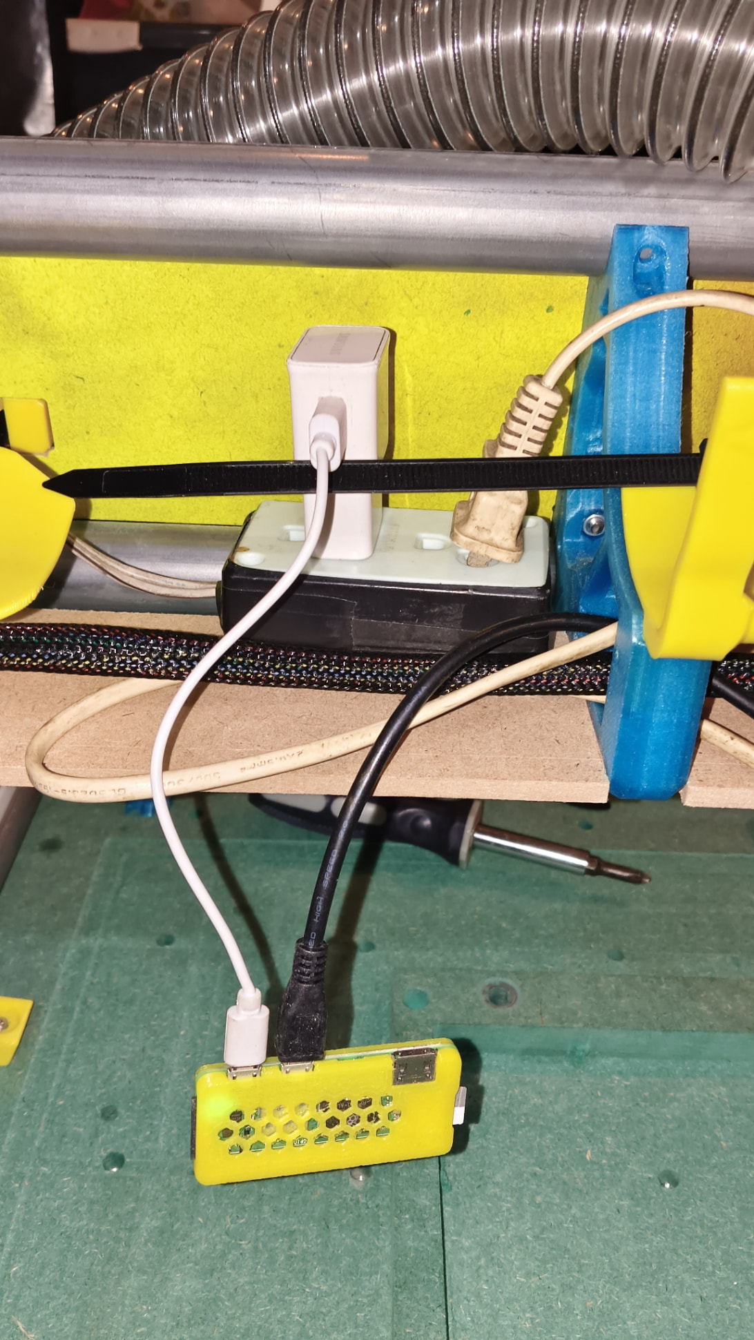
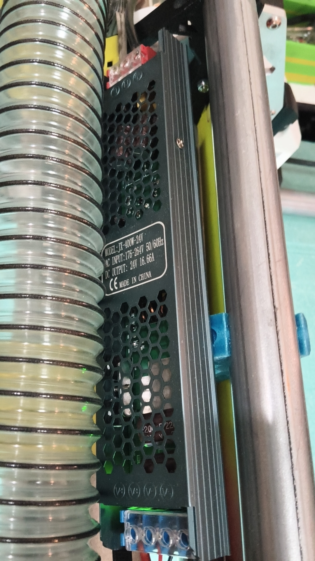
The USB is the klipper raspberry Pi which also Provides Wi-fi linkage. My AI assistant has recommended not powering the Pi from the SKR control board as well. Currently it’s at the Opposite end of the gantry is that’s just how the wires naturally laid. The second power wire there goes to my 24 Volt power supply which goes to the SKR Control Board Once I get the proper 90 USB adapter I intend to make a control box and everything will be incorporated. I’m hoping to power this 20 Volt brushless router with some kind of external ESC electronic speed control that will allow for spindle control from Clipper and seperate router power supply. My plan will be an additional 24 Volt supply which I think the router will be able to handle at least the motor once the factory electronics are removed. My understanding of grounds is there is no zero voltage there’s only the differential between two references. It’s actually quite an interesting subject
I used AI to restore and enhance the old photo, crop it into a portrait, isolate her from the cluttered background, and build a cleaner bust-style composition:
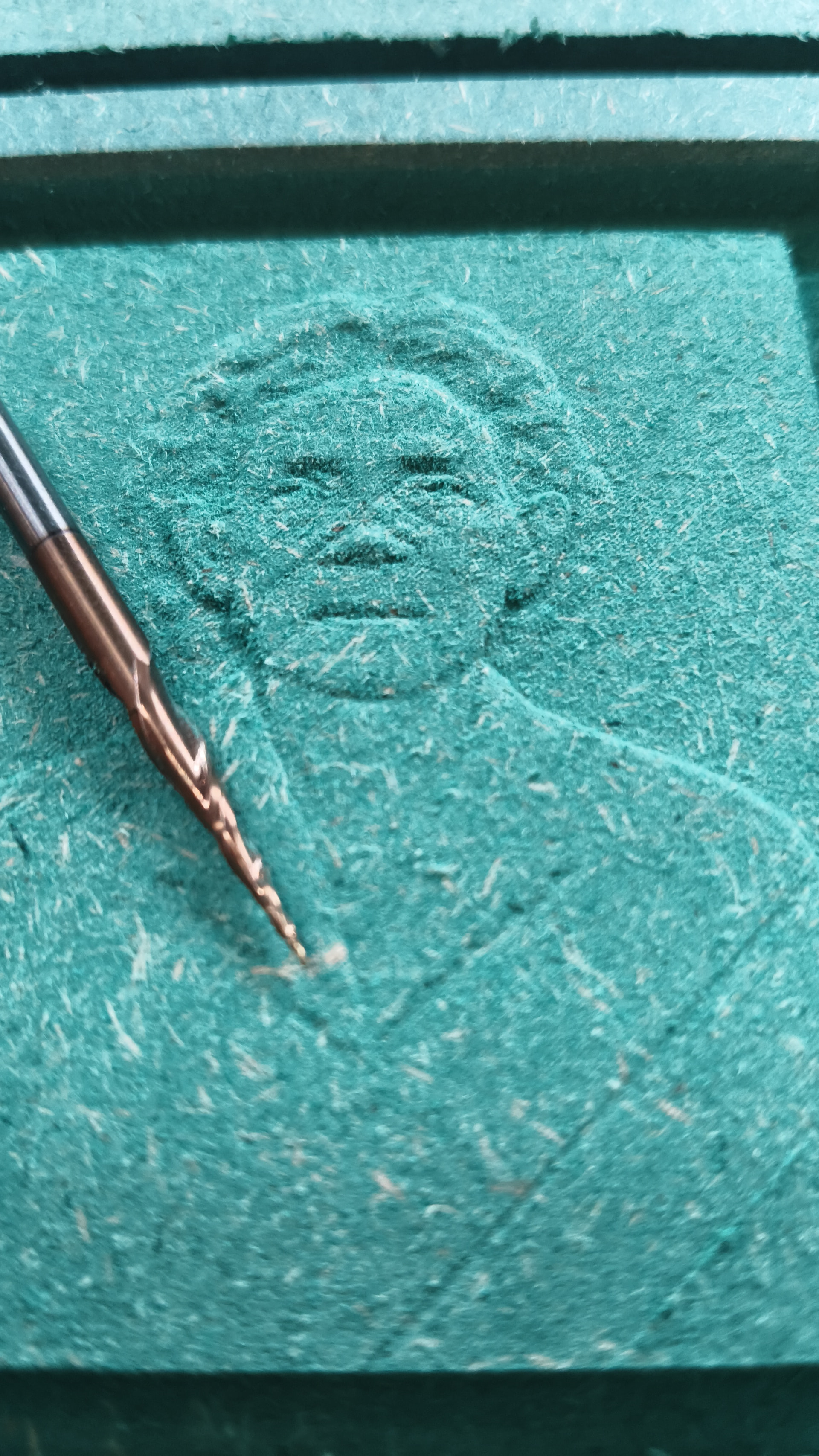
The next image is not simply a black-and-white version of the photograph. It is a grayscale height/displacement map: lighter areas are intended to become higher points in the carving, darker areas become lower, and the mid-grays create the transitions between them. That depth information is what gets converted into the actual 3D relief surface. This was generated by Chatgpt in this case.
.
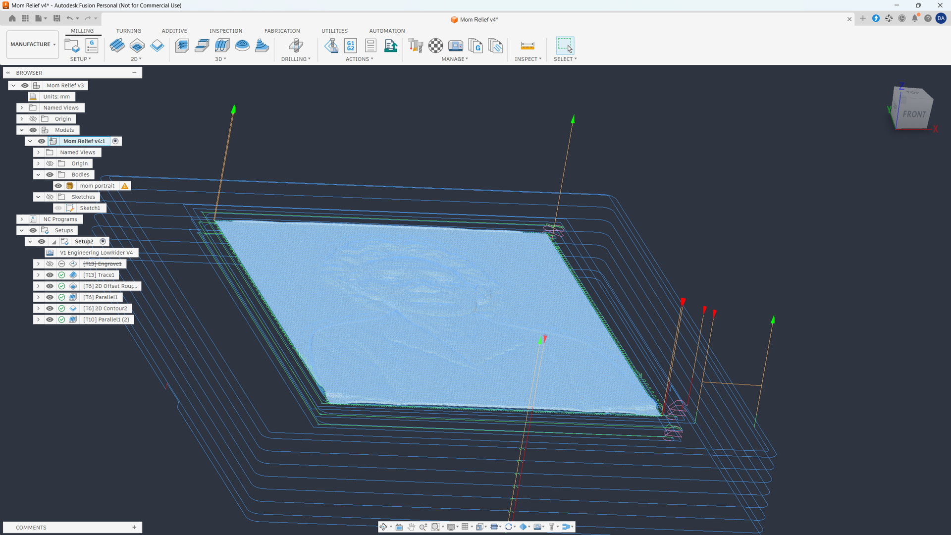
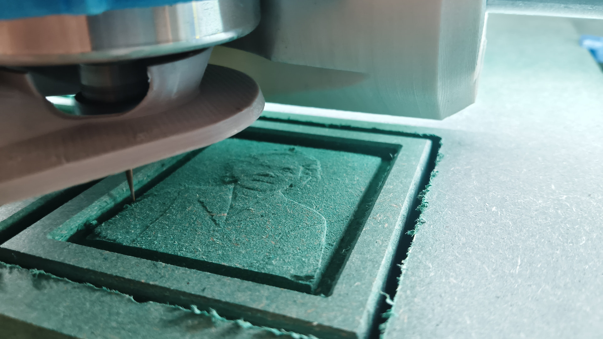
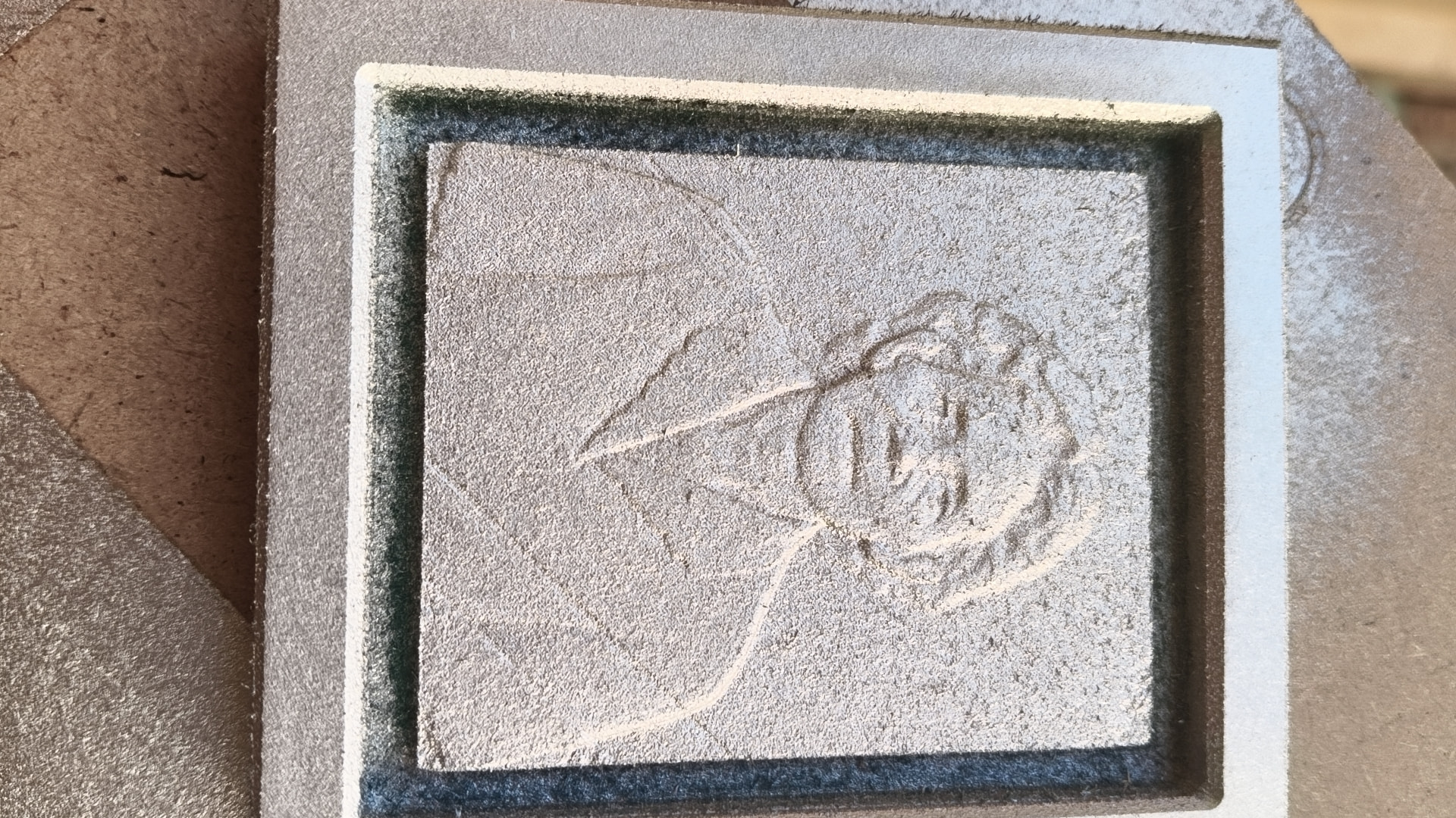
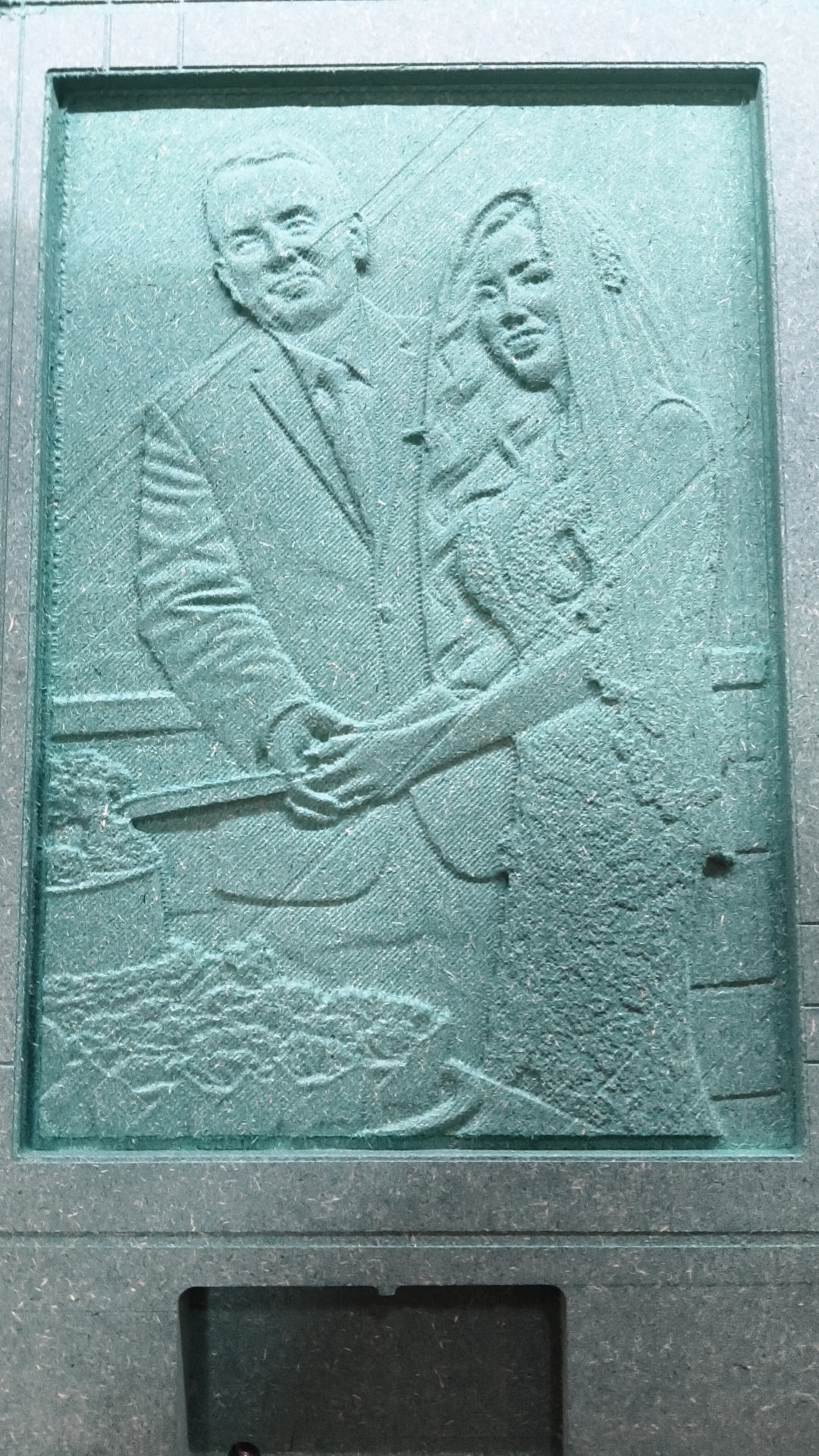
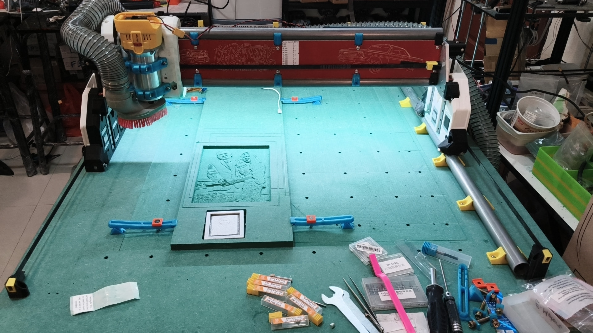
The ridiculously small .25mm radius ball nose tool that was used for the detail work on this very small model. Total machine time was just over an hour. Most of that being the finish pass. Three tools were used the initial chamfer was done switched to an 8th inch end mill that did perimeters and the rough cut and then switch to the ball nose for the finish pass.
It is still very much an experiment, but seeing an old photograph make the trip from image restoration, to a grayscale depth map, to a physical CNC carving has been pretty fascinating.
Hooked the “20v” brushless router up to a 24v power supply. Only issue is regen on deceleration pushing voltage too high and the power supply shuting down. Must pay attention to slowing down slowly. Better yet shut it off, set to lower speed and turn it back on. Just ran this ~3hr job without issue.
Not yet understanding the banding and the moves are diaginal so not like an axis hanging up. If steps are dropped, the change should not recover. Need to look at the toolpath. I can’t think of a scenario that it’s a LR mechanical issue.
Had this on a smaller tool and was looking at 24+hrs of machine time. In the process discovered some issue with my klipper/cnc pendant choking on the 50+mb gcode file but I think it’s resolved.
Think I have everying on hand now to get the electronics install finished.
Sounds like a job for a Zener diode. You run a 24V Zener between the terminals. When voltage goes too high, it conducts and lowers the feedback, so the PSU keeps working.
Had pretty much arrived at the same conclusion. Research indicates you need a load to dissipate the surplus energy with as well? As the router will not start by switching on the 24 Volt supply as a safety so if you install a fresh battery the router doesn’t start spinning until you power cycle the switch. So control is only possible to shut down without tearing into the router. I have added a pause in my post for spindle rpm changes.
I would like to go to a VESC Speed controller, Replacing the router electronics. That’s a whole nother project in itself. Would allow remote RPM/spindle control. Unfortunately this would cost more than the router did. So with the these limitations I’ve decided just to live with it for now as it’s more than getting the job down and significantly quieter then my 220V router at half the cost.
This project is proving to be A lot of fun. Started yesterday on coming up with a Maxwell kinematic coupling for quick Accessory tool changes. I’ve changed my router mount so I need to adapt something. Having a large scale gantry to which you can adapt various tools Opens up a fascinating world.
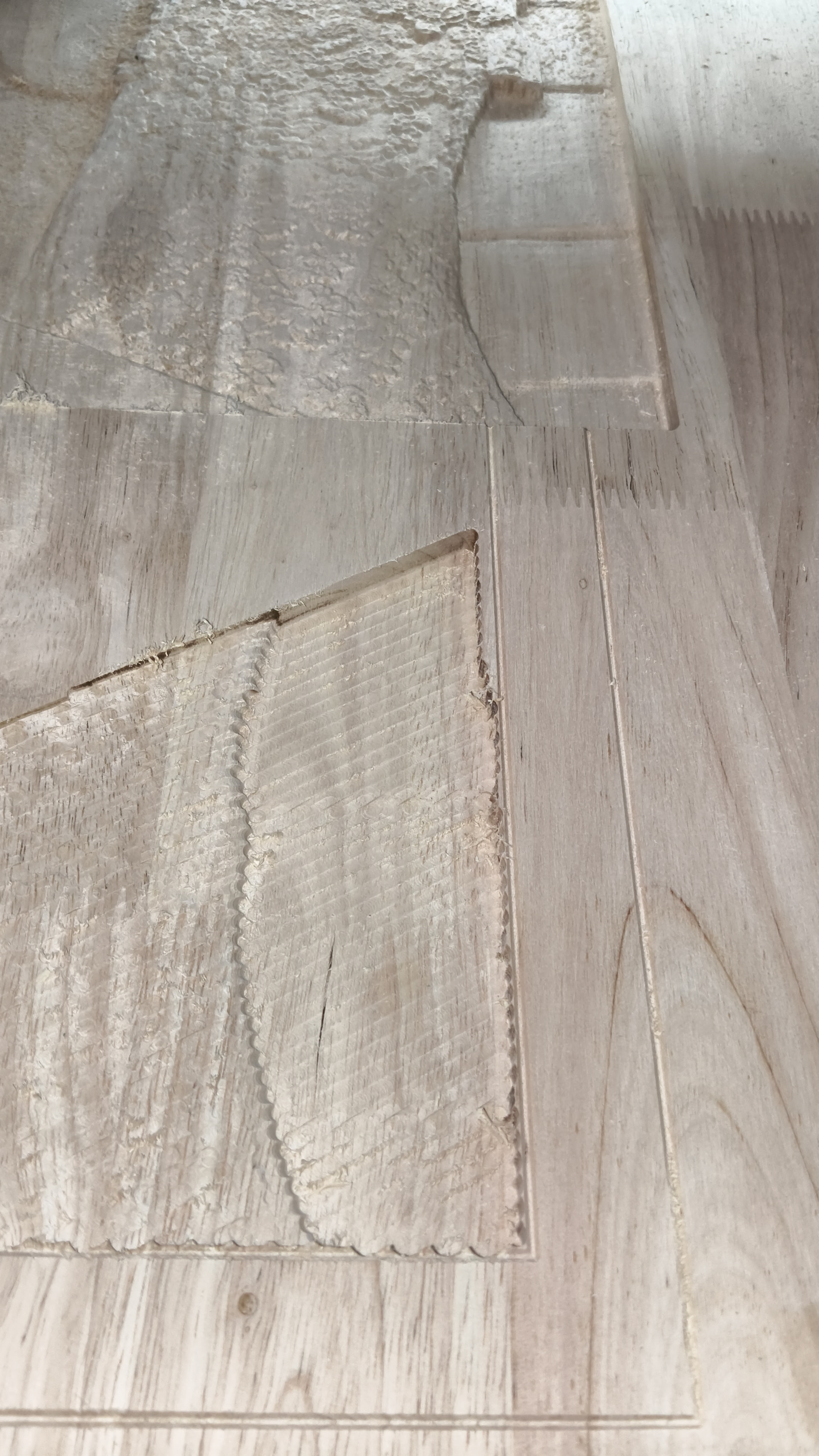
First attempt, the cut on the bottom. Used a 1/8 1f upcut, trying for a 2mm step over at full depth. Managed to drop some X steps it appears, notice how the right side of the cut veers left as steps are lost. Thinking to add some way to tap off on the endstops to check position to verify during a job. 2nd Attempt above it.
Only have a couple 1/4 cutters, both regular straight flute router bits, one is a ball end. Changed Strategy to What fusion calls morphed spiral. The initial entry with the 1/4 ball at the center of the part was two aggressive for a full depth cut and stalled out. Same result with the straight 1/4. As this was going to take forever was trying to get this done in a single full depth pass with a 2mm stepover. Ended up doing an additional Spiral morph with multiple depths to gain access for the remaining full depth morphed spiral. Managed to get it roughed in about 3 hrs on the straight 1/4.
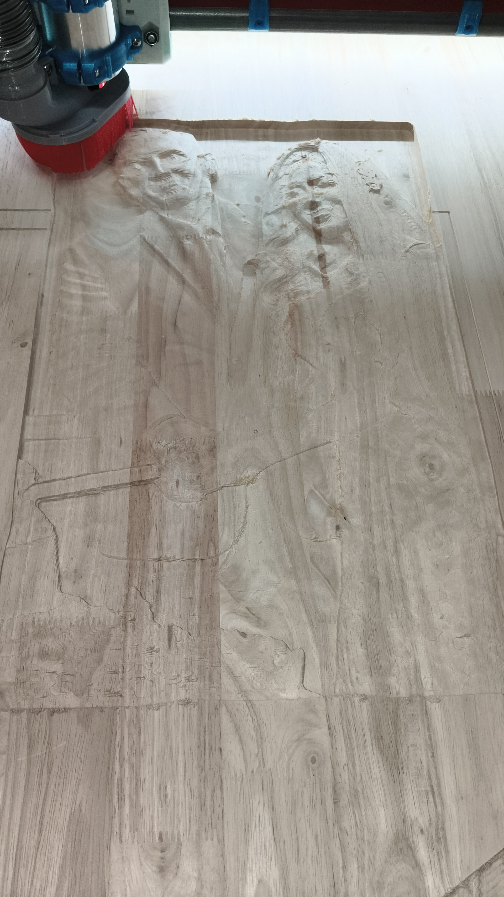
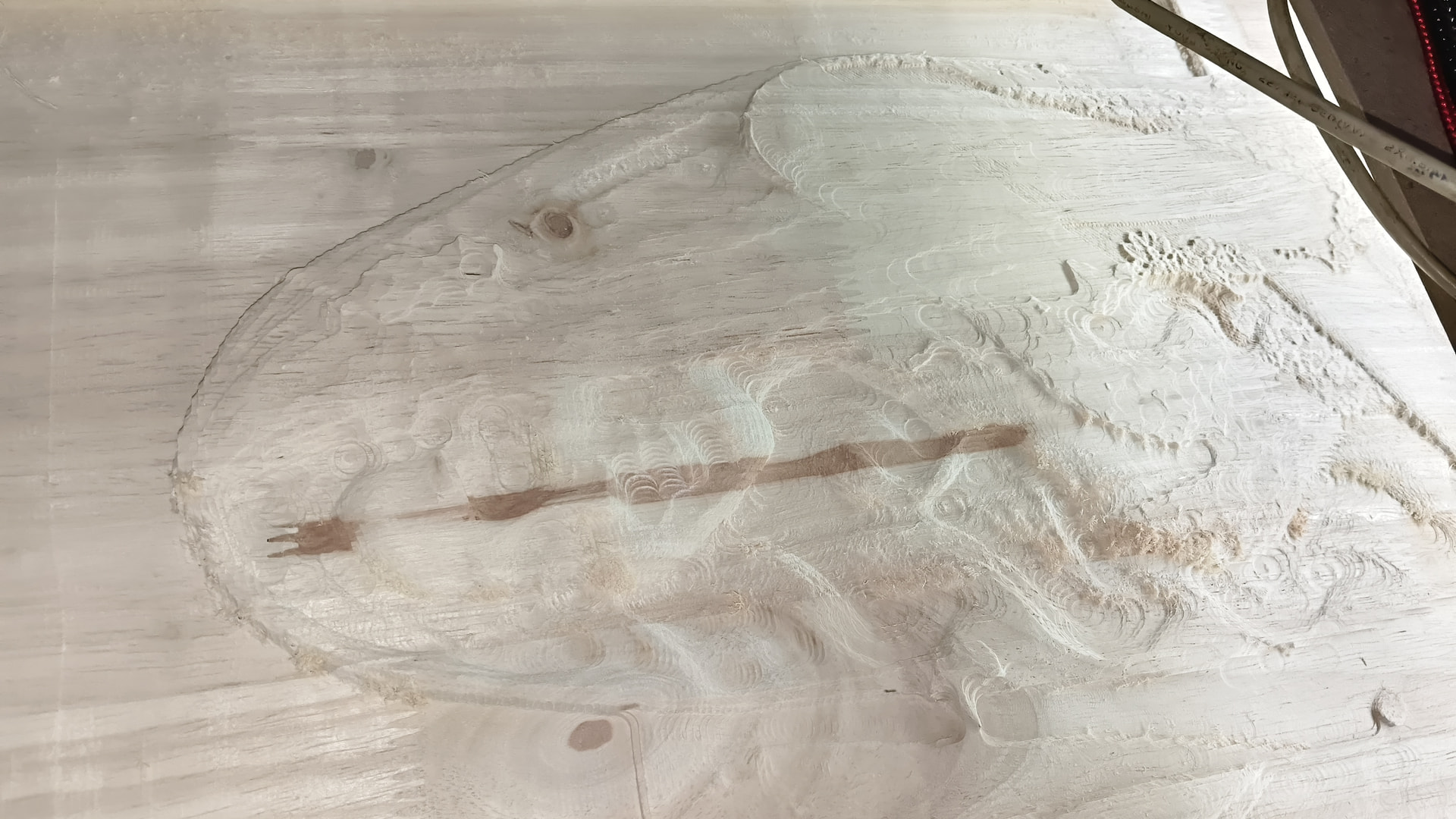
Finishing with a 2mm ball on a 45 deg parallel .2 stepover. Will still take 6-7hrs. 41% done in below photo. Can see the detail in the finished flowers on the dress.
Tragically there is some discolored heart wood thru the center of the bride. Considering pocketing it out, plugging it and remachining the plug… would be a good experiment I guess.
First cuts on real wood. Any recommendations on the proper bit to rough with? I guess a 1/4 1f upcut but interested in options?
Having fun but this has really bogged down fusion as I supposed it would about any CAM package. still have a lot to learn but enjoying it!