What program are you creating the DXF files in? I have found that two sided jobs require some trickery in Illustrator to get absolutely perfect the downside being that if you do it in Illustrator then you have two DXF files you need to setup in ESTLCam. If you do it in ESTLCam and the cut parameters all stay exactly the same you can cut your CAM work in half. But you need to trust how the flip works in ESTLCam. And you’ll also need a registration system you can trust on your machine. Either locating pins/dowels or a 0,0 fence setup and a homing system you can trust. You could add a 1mm X 1mm square to the DXF artwork and use that as a reference point when flipping your work in CAM? Adjust the grid to 1m X 1mm and zoom right up to make sure it lines up where you need it to? Make sure you flip all of the art at the same time, not piece by piece. That’d be a nightmare to realign.
I’ve only done it once (eight times with the same files though). If I know my material dimensions I’ll go into Illustrator and set up a rectangle that size and then position all my bits inside the rectangle including locating hole(s) for some sort of dowel based registration. Using the reflect tool in Illustrator I can select everything and flip it to make sure it lines up dead perfect (zoom right in close to any sharp corners etc to check or switch to artwork mode and zoom in to check). The key is the outer rectangle.
By default the reflect tool in Illustrator flips things around the axis you specify (horizontal or vertical) based on the object’s mathematical center. That’s fine if all you have are evenly spaced circles across your entire workspace or in your case are running a symmetrical job. But if you have an assortment of shapes then what is “left” on the topside will be “right” on the bottom side and you need to make sure you flip and get it to the right place. (Yes, you could also flip top to bottom I guess.) By using at least a two point registration system and keeping that in your artwork you can easily verify the flip. I’ll try to explain with screenshots.
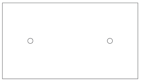
Let’s say these two circles are my dowel holes:[attachment file=“Screen Shot 2019-01-29 at 10.30.57 PM.png”]
I have made absolutely sure that they are the exact same distance from each side and perfectly centered both top and bottom and left and right. Illustrator makes this easy. After ensuring both circles are horizontally centered to each other, group the two circles. Then align those and the rectangle based on their horizontal and vertical centers. By grouping the two circles they are treated as one object so the center of that object is the mathematical point right between the two. (You can use this artwork to drill in your alignment holes on your spoil board. And then save the Illustrator file for future two sided work - you can use the same holes.) As long as the flip lines things up where you need based on these holes lining up you’ll be good. If I flip this entire workpiece it’s identical. Left/right or top/bottom. At this point it doesn’t matter how I flip it. That changes based on the artwork to be cut.
Let’s assume either you’re doing some 2.5D machining or your bit can only go halfway through on each side because your material is thicker than your cut depth.
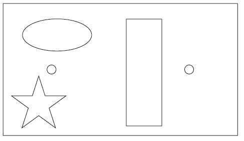
If this is your artwork:[attachment file=“Screen Shot 2019-01-29 at 10.34.24 PM.png”]
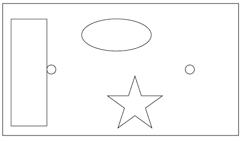
and you just flip the artwork, look where it lines up:[attachment file=“Screen Shot 2019-01-29 at 10.35.16 PM.png”]
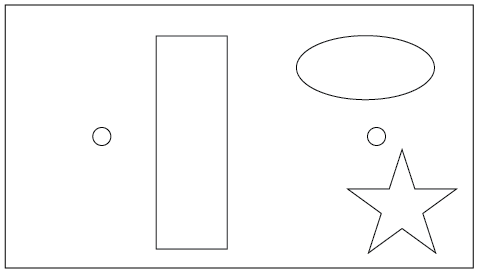
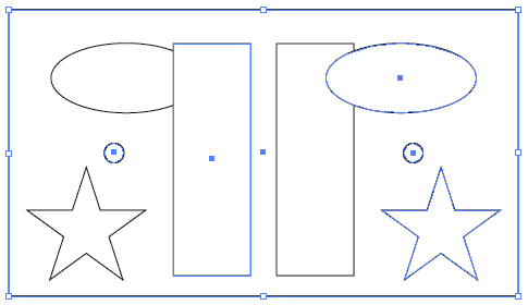
If however you select the entire outer rectangle (including the registration holes just for verification but you really don’t need to) look what happens:[attachment file=“Screen Shot 2019-01-29 at 10.37.45 PM.png”]
It’s because the mathematical center of the artwork is based on the outermost object - the rectangle. So everything lines right up. Here’s a flip of all of the artwork INCLUDING the dowel holes with the topside still visible:[attachment file=“Screen Shot 2019-01-29 at 10.53.17 PM.png”]
The dowel holes line up perfectly.
I have no idea if that helps at all…my apologies if I’ve just completely confused the issue. I’ll reread this once it posts and edit it if I think it’s a mess…