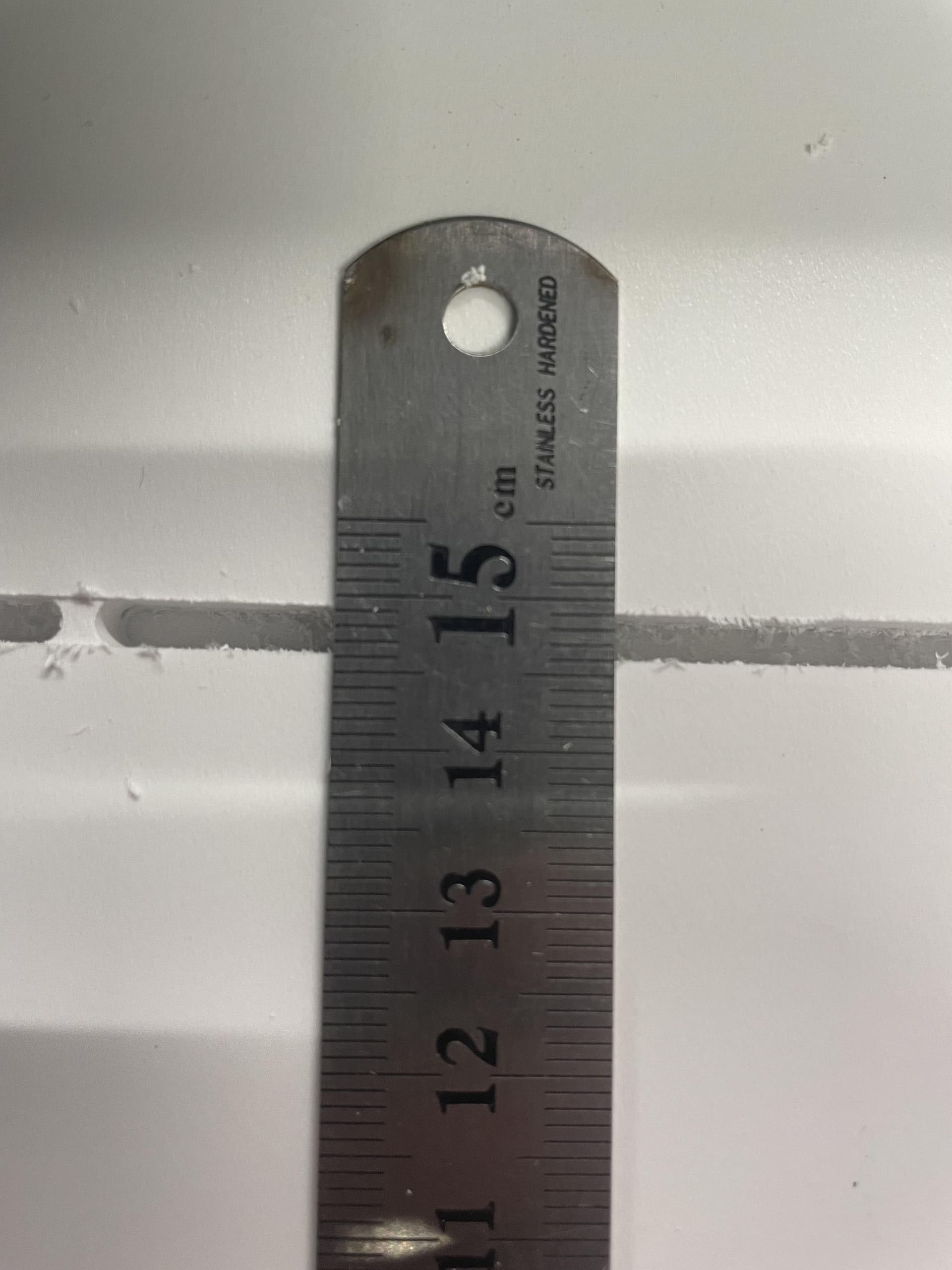
So this is strange - I’m cutting rectangles out of Foam that _should be 302mm x150mm on my LR3 with a 1/8" 2 flute bit.
First set all came out 302mm x 146mm
So I homed and checked my machine, then made a hole, moved Y 100mm , made a hole and spacing was perfect so I opened the gcode produced by estlcam. I’m using the ‘Part’ operation
Bottom left of the part is 10mm off the X/Y Origin
So on the X Axis it looks like its starting point is 10mm - /12 the diameter of the tool but on Y it isn’t.
Which makes sense for what I’m seeing in the parts are undersized by the thickness of the bit.
Am I missing something? I can’t figure how such a basic thing can be wrong.
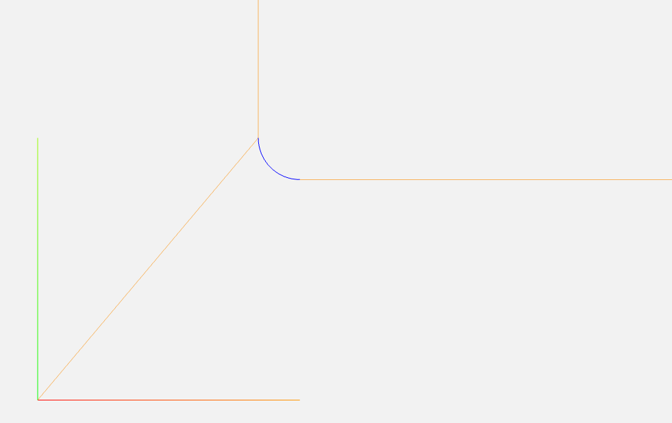
Go to the starting point less 1/2 the bit width in X
Turn a curve with radius 1/2 the bit width around the origin point until you get to the starting X point and 1/2 the bit width less in Y.
Go straight 302mm in +X
Turn a curve with radius 1/2 bit width until you get to the start point in Y and +1/2 the bit width in X
Proceed 150mm in +Y
Turn a curve with radius 1/2 bit width until you get to max X size and Y + 1/2 bit width
Estlcam uses curves around the sharp corners (G03 commands ij this case) the 1.5875 is the radius of the bit, so it keeps it your dimensions plus that.
The rectangle that it cuts is from 8.4125/8.4125 to 313.5875/161.5875 this should result in a rectangle 302mm wide and 150mm high. The gcode here matches what you are asking for, provided that your machine is obeying the arc commands correctly.
Estlcam has an option to turn off arc commands. You cound try that and see if it helps. If so, then it is a different error that your machine has. I dont think Estlcam is to blame here
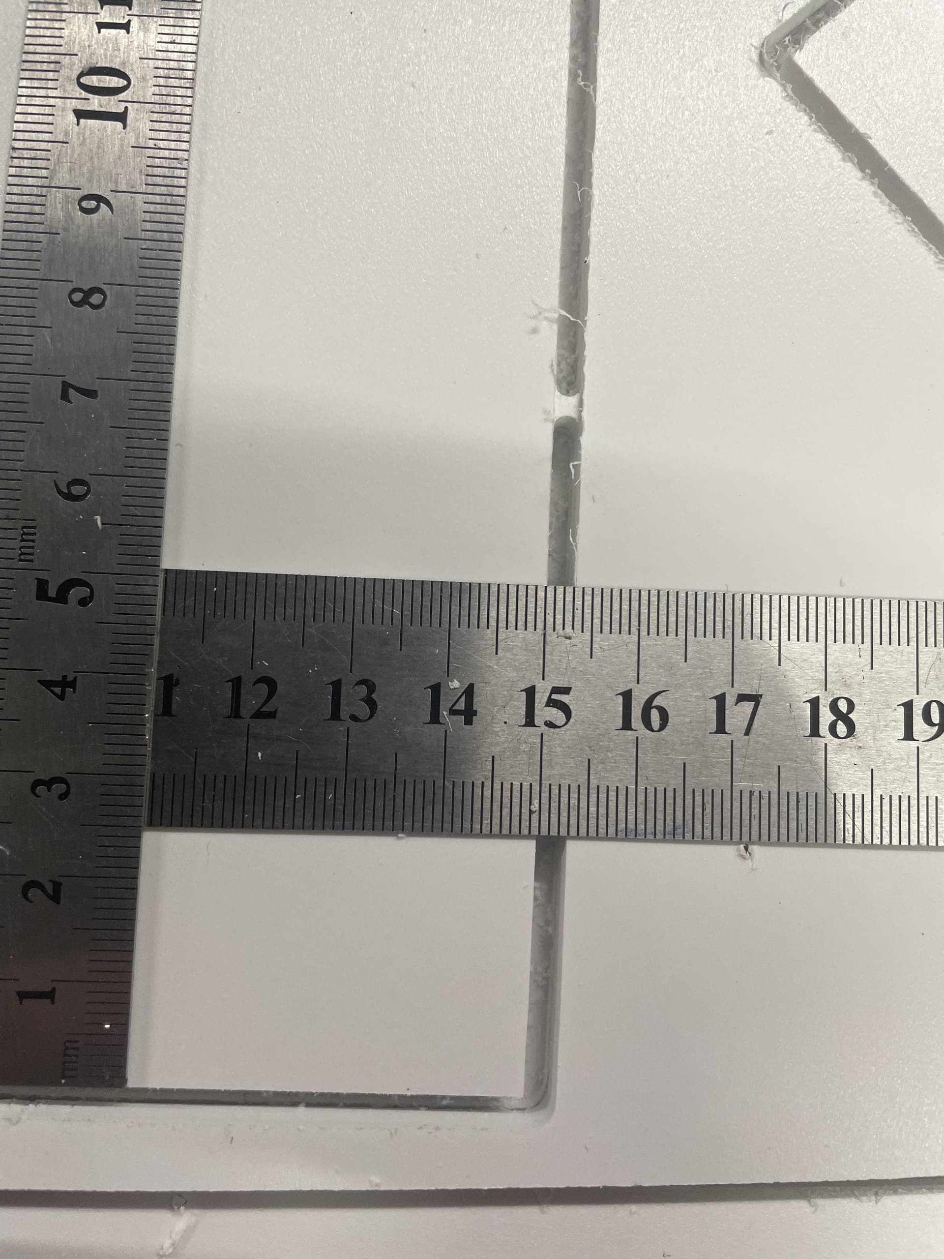
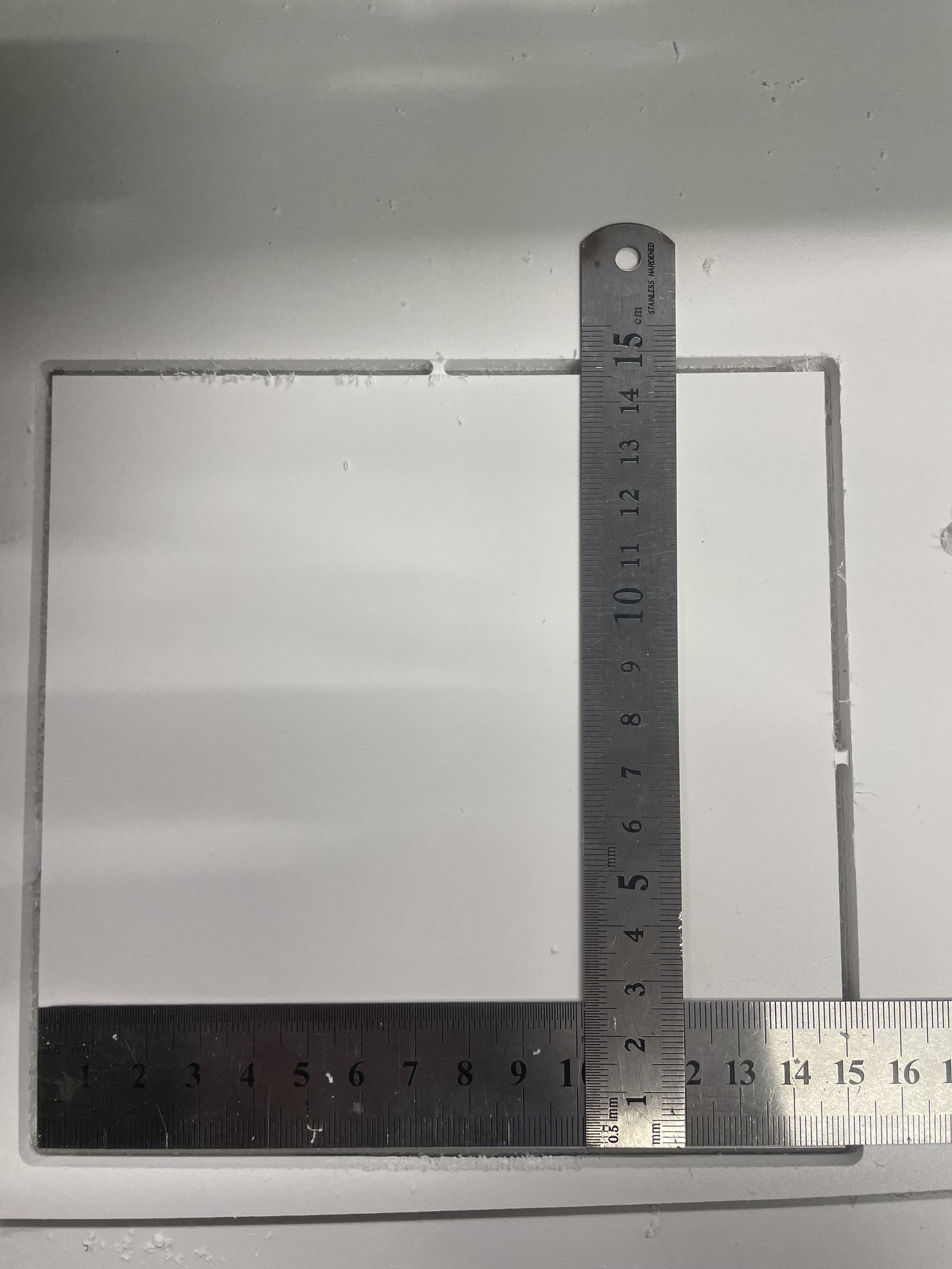
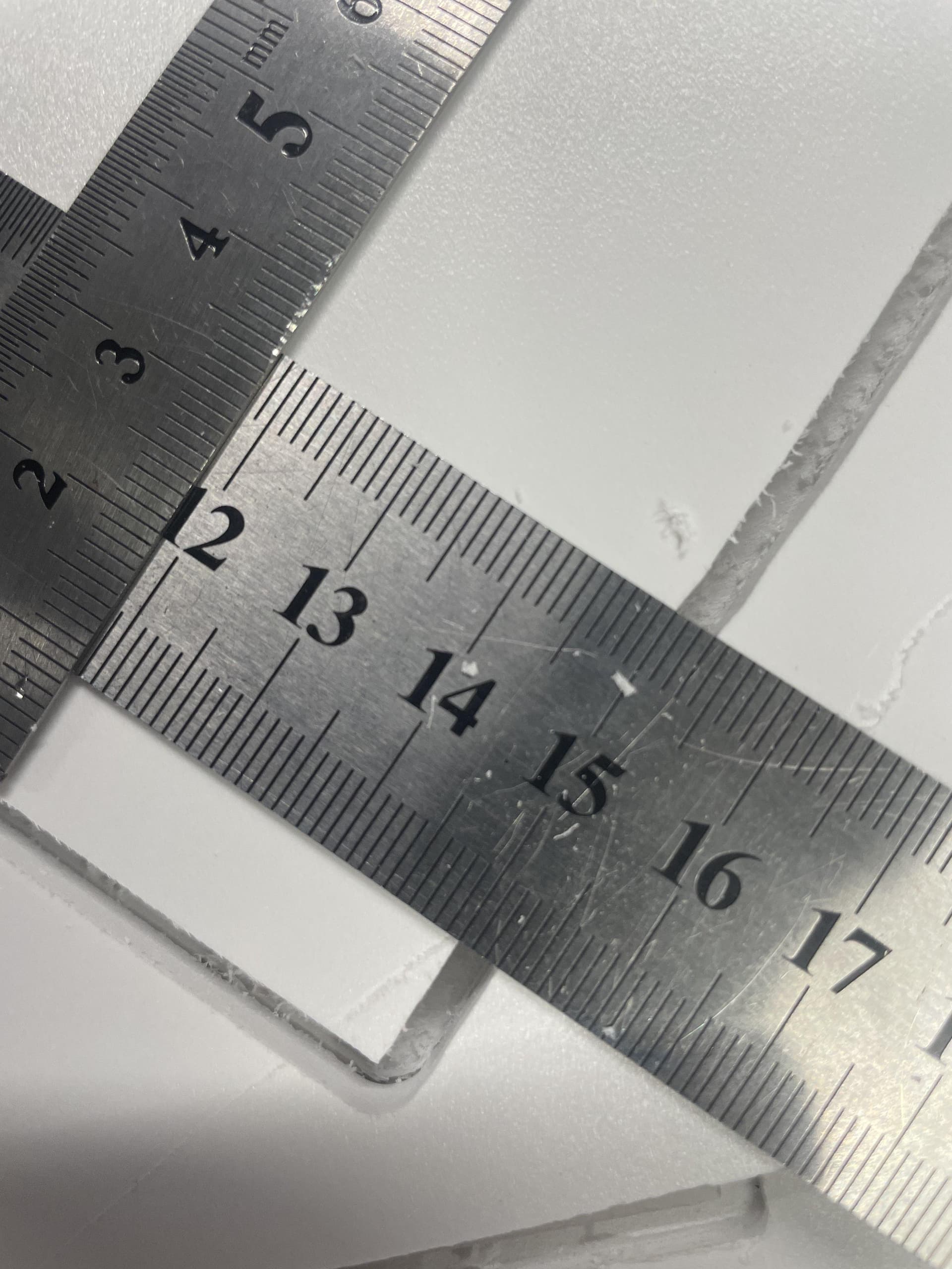
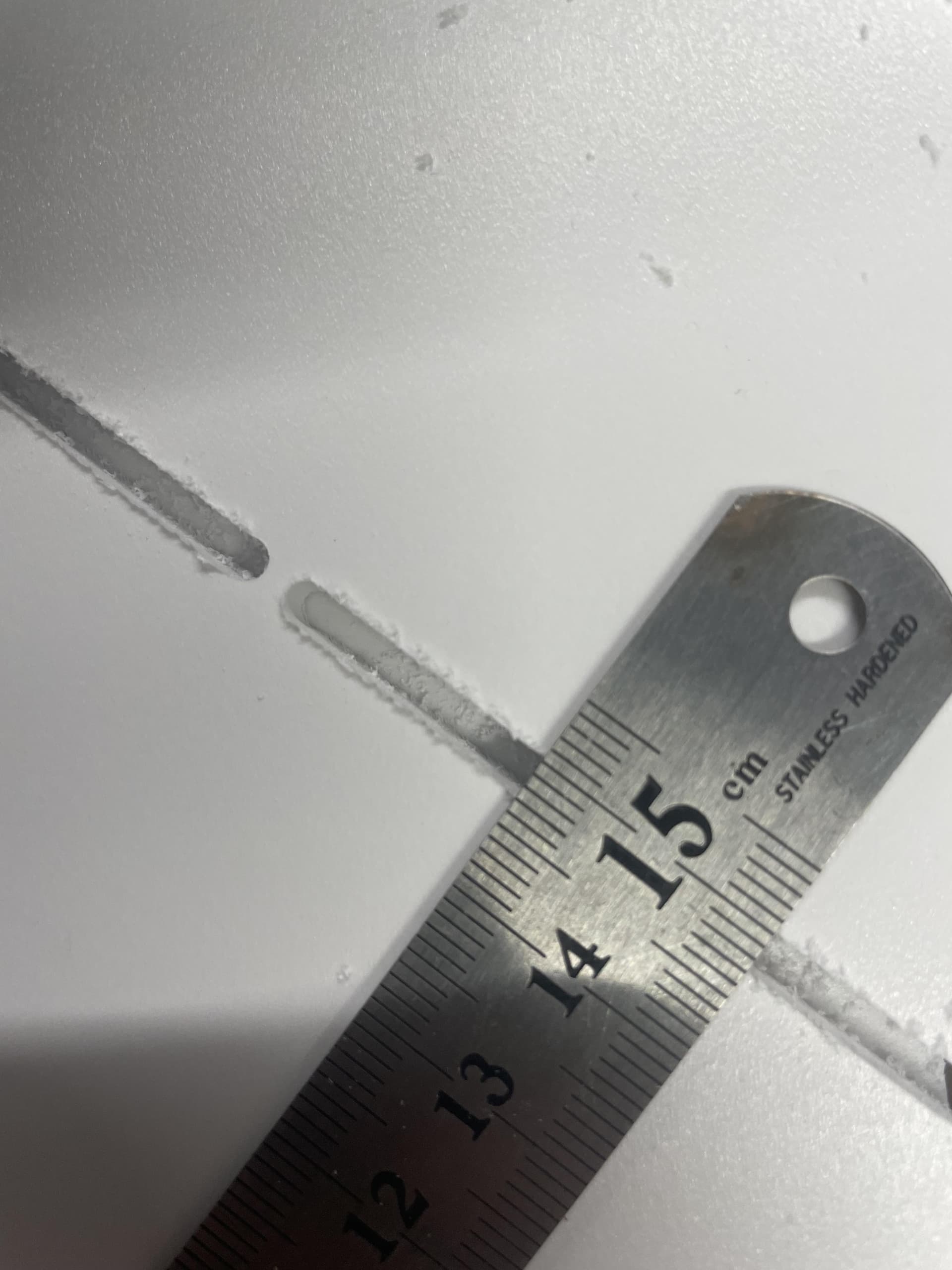
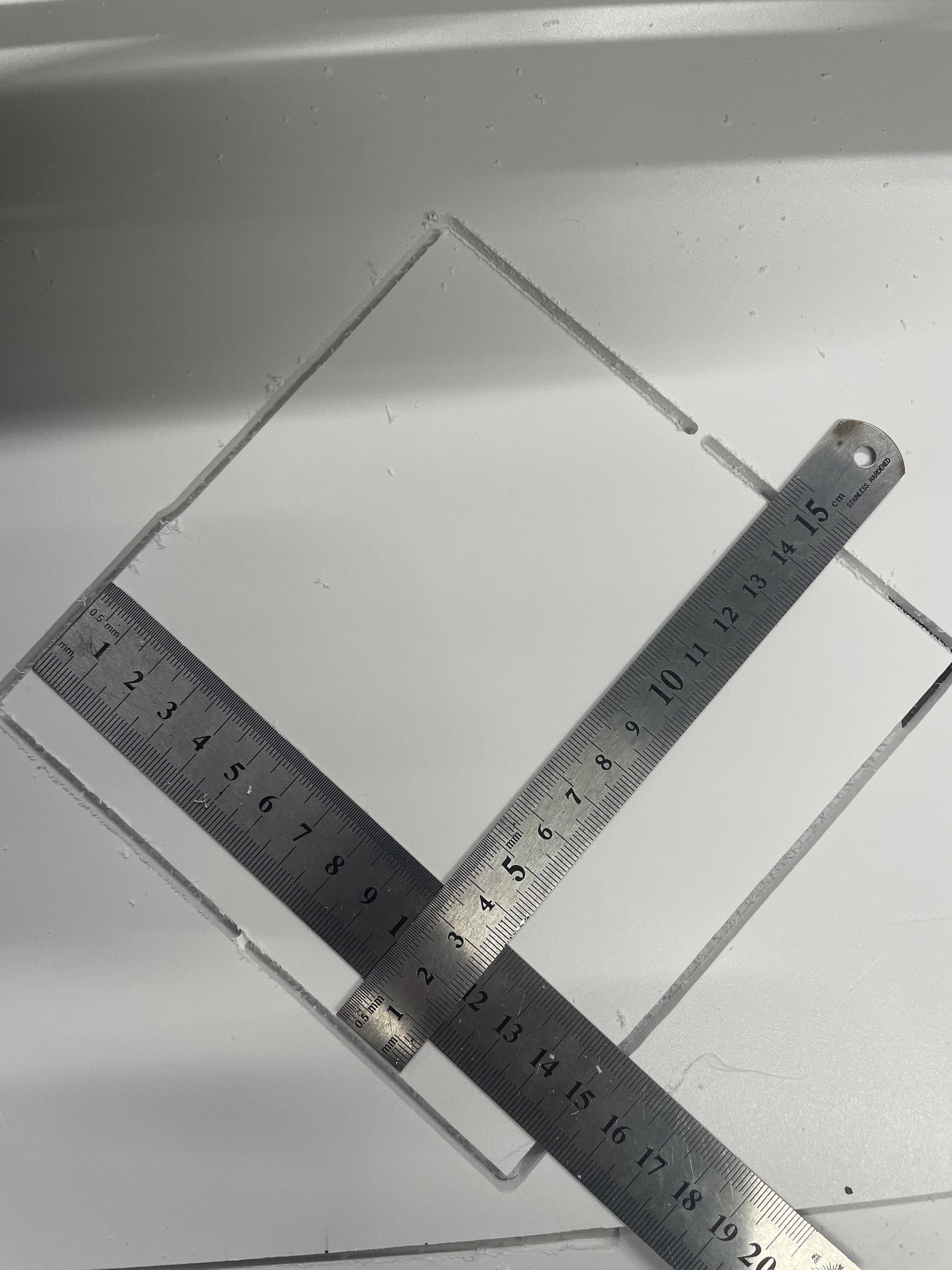
Weird. So I made a test file with 2 150mm squares, the second rotated by 45 degrees. My reasoning being that if there is a mechanical issue with the Y axis the second square should turn out to be a rhombus.
If you jog Y from zero to as far as it can travel, do a tape measure and the controller agree? Have you used the Estlcam measuring tool (middle click and drag) to more or less confirm (no snap functionality) your imported drawing dimensions?
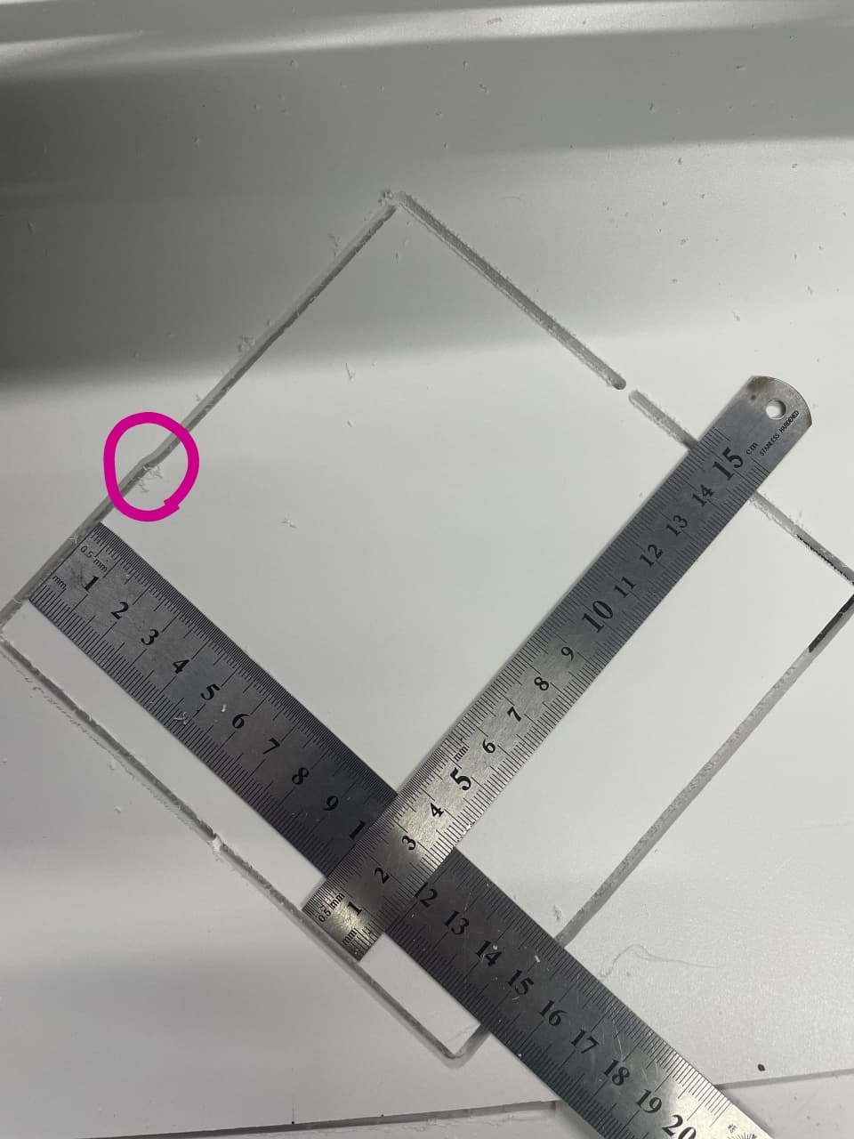
Good spot! I went back to the machine and gave it the old wiggle test and discovered the left Y motor pulley has a bit of play, the grub screw on the flat of the shaft was loose, not enough to let it spin but enough that there is backlash!
Disassembled the motor mount and reseated the grub screws with some blue loctite before I left for work this morning - I’ll run another test cut when I get home but I am hopeful that’s the issue - the backlash as it takes up the slack on the Y axis.
To close the circle on this -I’ve only got a chance today to get some free time to check after retightening the grub screw on the Y axis motor pulley.
Ran the same 150mm test squares today and they’re both nearly perfectly 150mm across so that was indeed the source of the error.
To aid anyone doing a search later on I’ll reiterate Y axis error in size was caused by a loose grub screw causing backlash. Thanks everyone who helped.