I’ve updated to the latest version of EstlCAM (12.072A). I’m trying to perform a 2-sided cut from a .stl file I created. I’ve looked at this topic but it is about setting up register positions. I did that by creating a separate job that just drills holes in the work piece material and then a separate job to do the same on the spoil board (mirrored).
My issue is, when I flipped the work piece over and started the 2nd EstlCAM job (the bottom file), it was going fine, then when it was towards the beginning of the finishing pass, it just cut right through the tabs I set up and that the 1st EstlCAM (the top file) left in place. Good thing I was doing this in foam so nothing got damaged or hurt.
Anyone tried doing a 2 sided cut recently using EstlCAM v12.072A?
Ok, after not having the time (or using my time on other projects), I’ve gotten back to testing. After watching Christian’s video (using sub-titles and slowing it down a lot ), I set up my settings just like he did in the video.
The only thing I really changed was to make my tabs 20mm long (vs. about 5). I’m guessing that due to the 2-sided cutting, you’d want more material for the project to hold onto so it doesn’t fall out. Since I was testing with foam, I didn’t think it mattered.
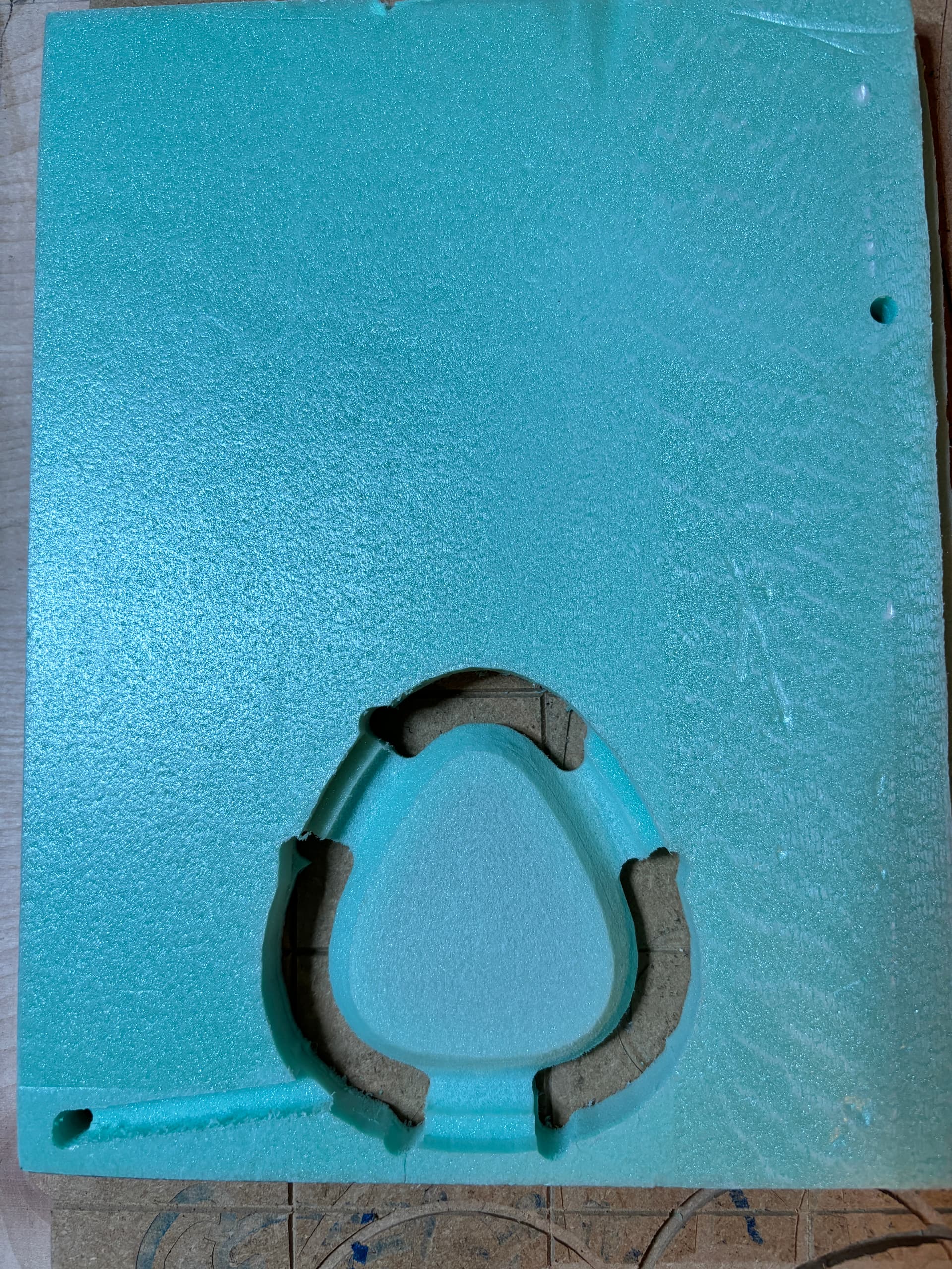
Here is Side 1:
[Note the cut in in the lower left corner. Of all the tests I’ve done, this still happens, but only with the Side 1 cut. I haven’t looked at the gcode yet, but I just used the Estlcam prompts to set things up. So I think this is part of the feature. Note to @christian-knuell ]
I still have to play with the machining strategy for the roughing pass and finish pass. I think I’ll stick to waterline for both (less sanding, I think).
I also noted that for side 2, it did a LOT of air-cutting around the outside edge where it was already cut out from the side 1 cutting. I’m guessing that is because you’d want to make sure both sides are cut out and not just ‘connected’ on the sides to the raw material.
Well, I noticed there were a few updates to EstlCAM and I updated. Now the initial dive in doesn’t happen. Still a lot of air-cuts, but I can understand that. I think doing the waterline was the best machining strategy, so I’ll stick with that. This is the result using version 12.100C
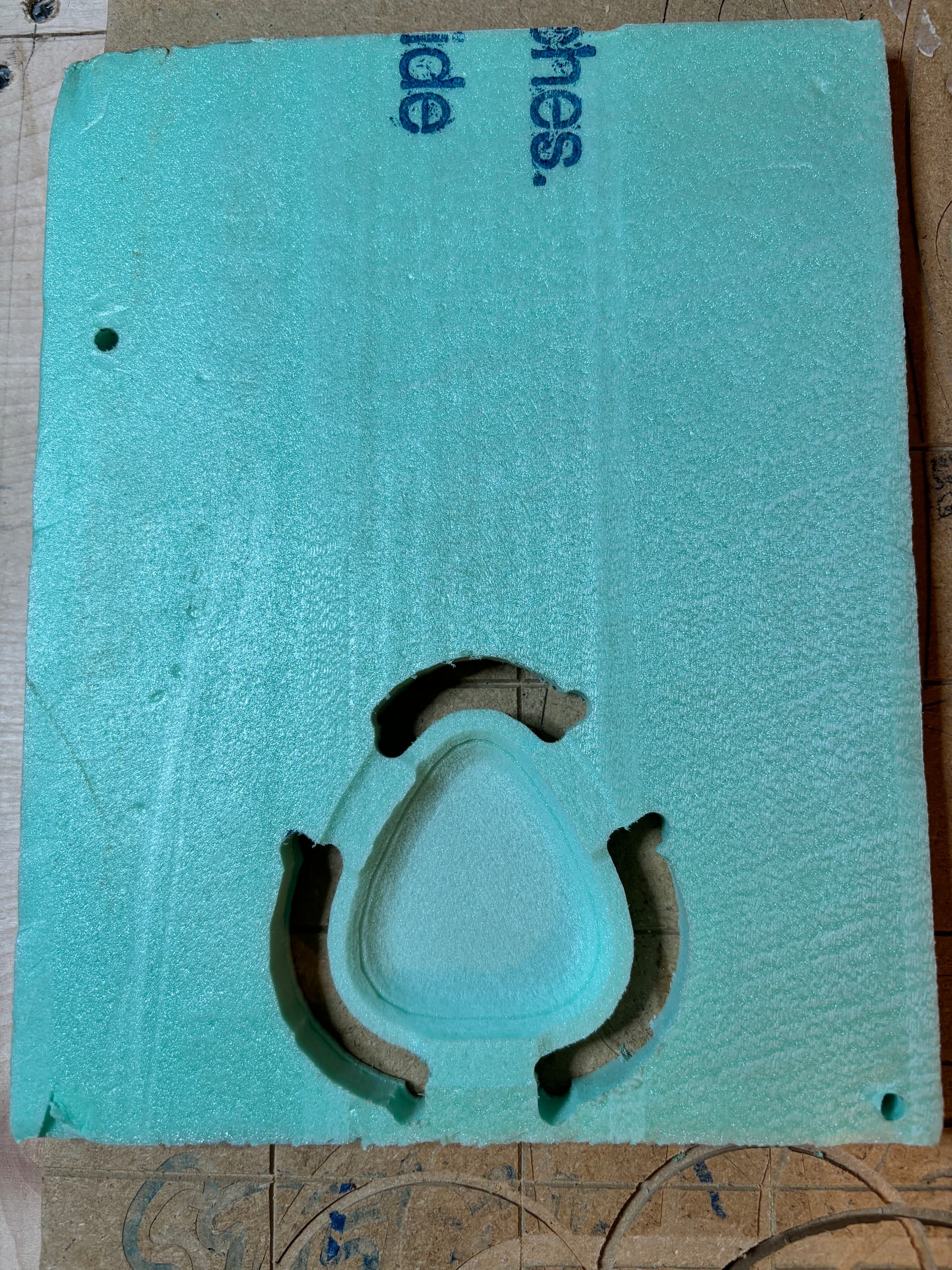
Top (2nd job)
(there does seem to be a line/rough spot inside the bowl. This is because I had to glue two pieces of foam together to get it thick enough for the job. The glue started to give out and that is why there seems to be a line/rough spot.)
Now to just find myself some wood that is think enough for this job. Next time I’m at the big box store, I’ll try to remember.
Finally decided to just do the job I wanted in wood (poplar). It took my 3 tries. The 1st two were messed up by me. 1st when I had a logo carved in the bottom inside, I forgot to just have the router raise up and stop. Instead, it raised and then it went home and cut right through the side of the bowl. 2nd time I forgot to add tabs. 3rd time worked.
But, I think there is still an issue with the 2-side cutting using a STL file.
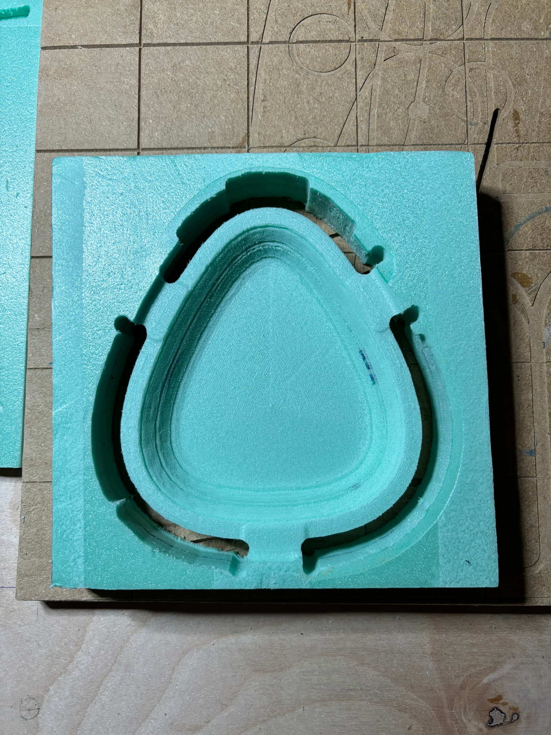
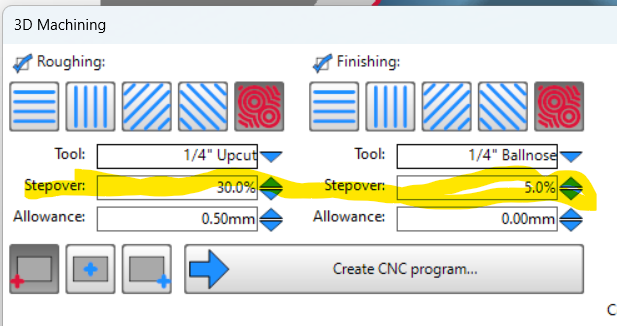
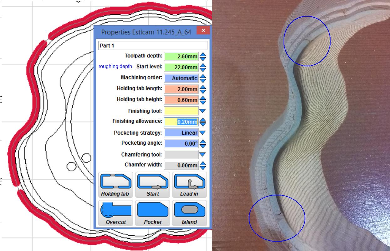
@christian-knuell Christian, It seems there is an issue with this feature. I’m not sure what the problem is. It seems maybe the calculations for the 2nd side uses the ‘Stepover’ from the tool list instead of the stepover that is provided in the 3D machining window.
The above is what I selected as my stepovers and my tool list has the default stepover as 40% with the 1/4" Upcut and 80% for the 1/4" ballnose.
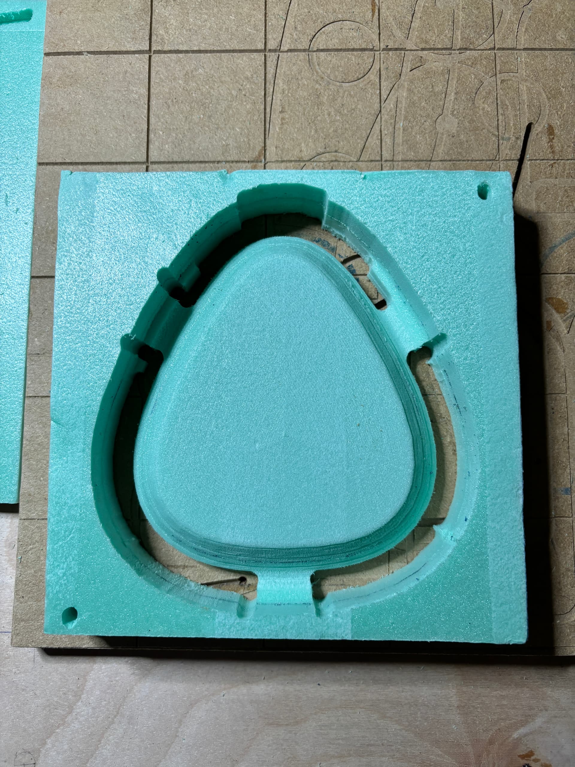
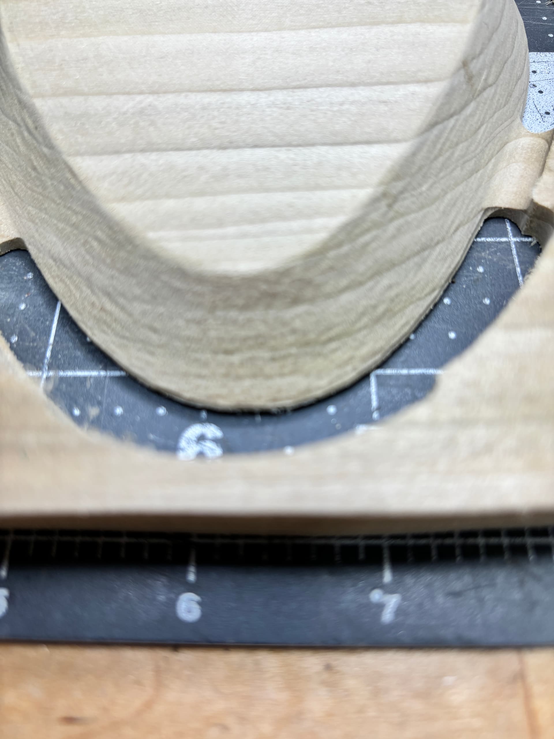
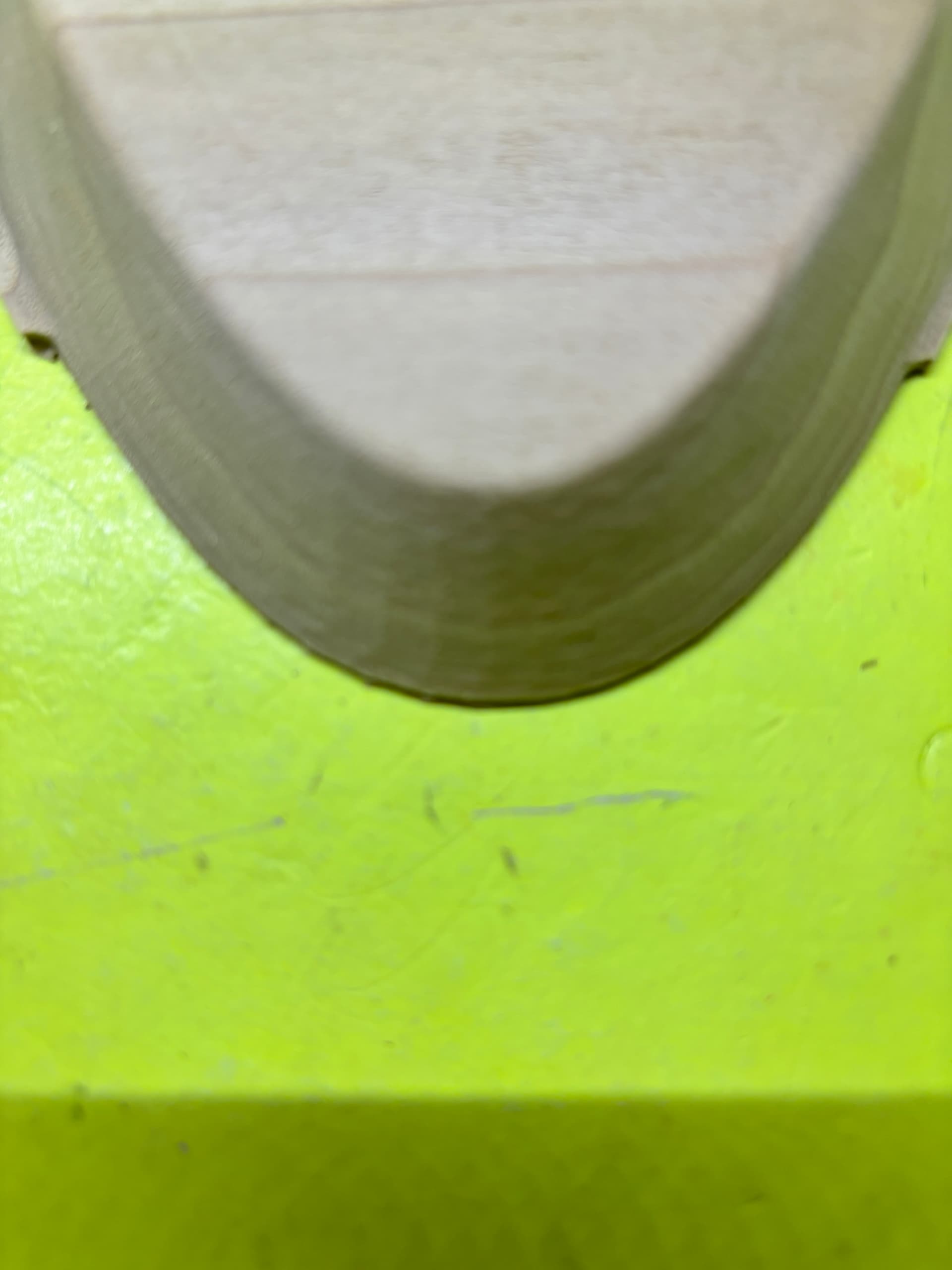
On the 1st side (bottom of the bowl I was cutting), the sides came out nice:
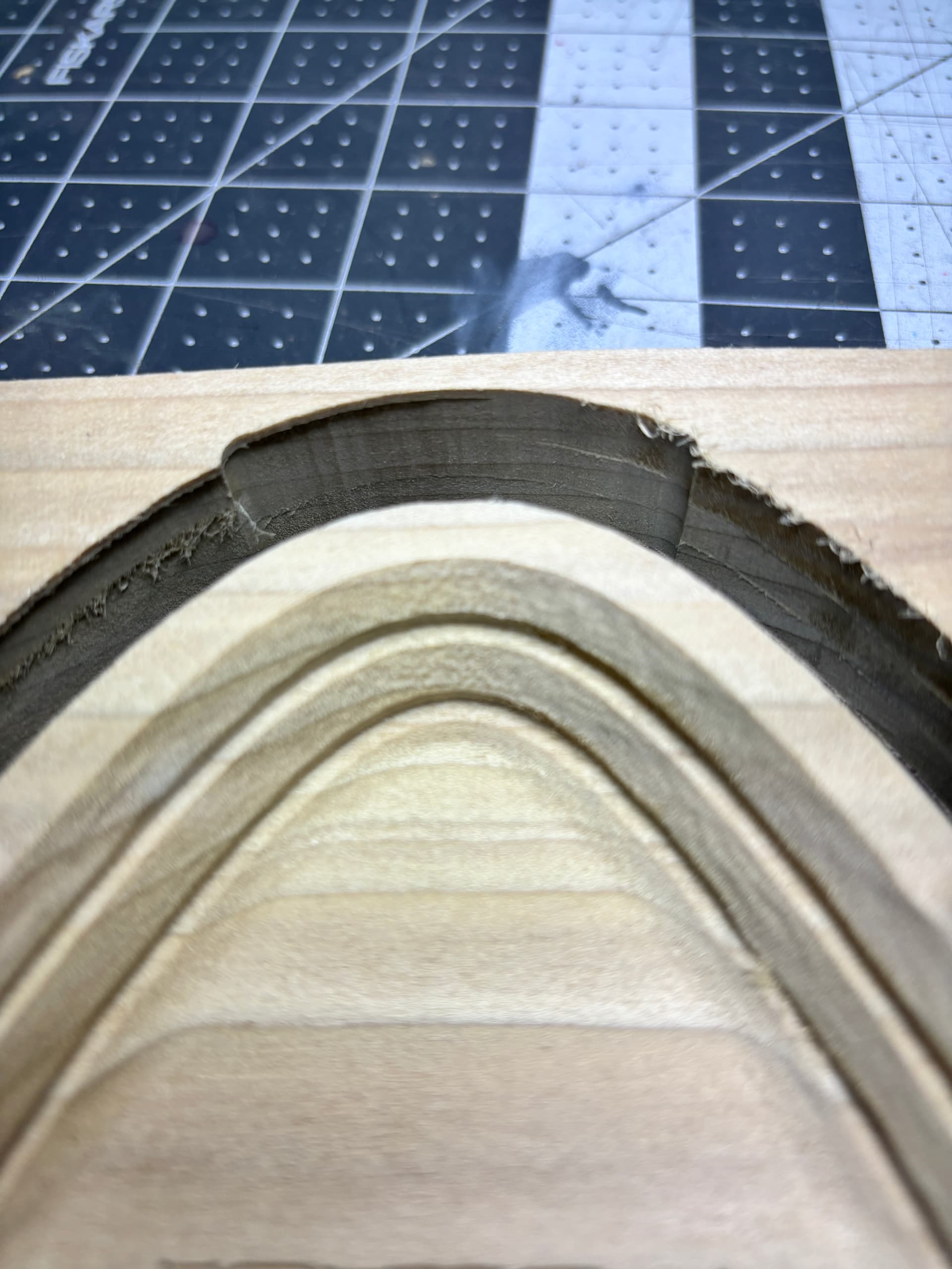
…but the 2nd side (inside the bowl), the sides came out as steps - as if the 1/4" upcut bit was set to a larger stepover (maybe the 40% as my tool list showed me):
Is there a bug here? This was done using EstlCAM v12.101C (I see now that there is a 12.102 version, where do you keep the version log so we can tell what changed?).
I’ve only done 2 sided 3D with the v11 solid of revolution, but I would try rotating the opened STL so that the inside of the bowl is up and gets machined first (material top Z0). Assuming you’re accurately resetting Z0 at the same spot after tool changes I would hope that the inside of the bowl would be clean - no leftover groves from the roughing pass and no funky raised tab bits extending onto the face of the bowl rim (neither is a stepover issue).
If you’re interested in letting others take a look/try, I think the forum allows posting zipped files.
After playing with Block Machining a somewhat similar project I would change my suggestion to using Free Machining (w/ 0 Margin) to do the inside of the bowl first. I hadn’t realized that Block machining does full depth perimeter cuts from both faces which is pointless for any project where the largest perimeter cut is on the face of the material, i.e. Block Machining/tabs is only needed for machining the outside of the bowl.
Use ‘Free Machining’ with 0 margin for the inside of the bowl first
Use ‘Block Machining’, providing the material size (width, length, and height) and set up the tabs for the back side (outside) of the bowl
the ‘Block machining’ will produce two files (a _1 and _2).
use the _1 file to cut the outside of the bowl - this should leave the tabs flush with the top of the material and cut away the full depth perimeter cuts (so it only happens on one side vs. both)
At least this is what I’m absorbing from what you are typing (this is my 1st attempt at this and would say still learning EstlCAM and CNCing ).
Your mention of material size exposes a flaw. I use a center origin and that looks like the only way to use both Free and Block machining because Free has no material size option. With a center origin the Block material size doesn’t matter.
…A better option would be two separate setups using Block machining with the two sided option unchecked. Open the STL with the outside facing up and do whatever you did before (e.g. add tabs) and save as foo_bottom.nc. Reopen the STL with the inside facing up and, with the exception of setting Margin to 0 (no tabs or full depth perimeter cut), use the same settings and save as foo_top.nc.
Setting tabs seems to work best when the clicks are made outside the margin, when clicking along the perimeter they can extend inside the perimeter which may explain the tab bumps on the top of the bowl rim (foam images).
Thinking about this method and using EstlCam to try/model this out, it looks like my answer. Will give it a try this weekend if time allows and report back when I do try it out.
Dave,
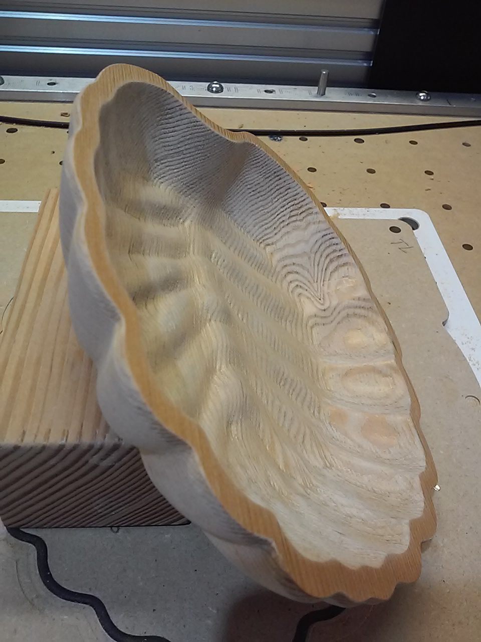
Thanks. your method worked fine. That project is done (from a CNC stand point). Now I need to do some finish sanding, sand the tabs down and smooth, and paint/stain the bowl.
It does look like there is a line, but I can’t feel it with my finger or fingernail. It should work it’s way out when I do a finishing sand. Happy days again!
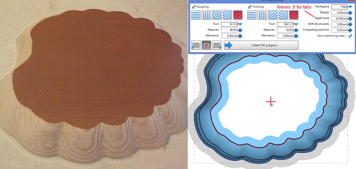
Actually, Free machining allows masking and the mask file can be used to do a separate tabbed perimeter path. A Depth limit needs to be set so that the 3D won’t go through. The tabbed path Start level is the distance from the surface to the already cut roughing depth.
My primary purpose for using a mask was to avoid having to unnecessarily machine the flat. I don’t know if it’s a bug, but when a perimeter Margin is needed a margin is added to the masked area and the G-code has to be manually edited to get rid of it .
Mask files are easy to create using the v12 3D Covert to 2D Drawing > File : Edit drawing. With a mm STL and (Setup : Basic : editor set to) Inkscape it’s Manual scale (mm) > Save as (default svg, no changes/edits required). The only twist is that the SVG needs to be opened (Workspace > Mask) as Pixel 96dpi (Setup : Basic : Length unit = Ask).
I don’t understand why you make tabs like this. In your right view with all the blue, you should be able to just click into the grey border to create tabs? Not at home to try, but I am pretty sure…
I achieved what I wanted. Using a mask reduced bottom machining time by something like 75%. That the tabbed path worked was just a bonus, something I tested for the community.