Version 12 has got that… ![]() I answere that question before, I already had the screenshot, seems to be a common problem.
I answere that question before, I already had the screenshot, seems to be a common problem. ![]()
1 Like
I think I am the one you answered before. ![]()
1 Like
Looks like negative finishing offsets are allowed now. ![]() (In V11 it would crash.)
(In V11 it would crash.)
2 Likes
Cool!
It mentions text engraving changes, I hope that means carves in general. That was the place that seemed to bit a bit wonky, it did/does most carves in sections and not a smooth finishing pass, at least not as smooth as I imagined it could be.
2 Likes
Negative finishing allowances have always worked fine so long as you didn’t exceed tool radius. The crash fix is that any number entry that exceeds the limit will be reduced to the limit.
…my detailed explanation from Estlcam International Facebook group:
The finishing allowance moves the cut path closer to or further away from the line. The path offset (center of the tool to the line) has to be a positive number, e.g. a tool with a 1mm radius and a -.9999 finishing allowance leaves a +.0001mm path offset. The only way to get to the other side of the line is to switch from a hole path to a part path (or visa verse). Using the example (a hole path), switching to a part path and using the same -.9999 finishing allowance would put the path +.0001mm away from the other side of the line. The distance between the two paths would be .0002mm, i.e. they would essentially be identical.
2 Likes
Huh, so I tried it and yes. I guess I just happened to always crash it whenever I went negative, so I never realized that it ever worked. That’s super helpful! And I don’t have to wait for version 12 to be production-ready!
1 Like
They calculate a lot more quickly. No more waiting five minutes after changing the diameter.
2 Likes
I miss user defined cnc code. In V11 is that with menu drilling. Does anyone know if that’s somewhere else?
I don’t understand the question. ![]()
You can add macros in a special menu. Maybe that’s supposed to replace it?
1 Like
Can you tell me where I can find that special menu?
1 Like
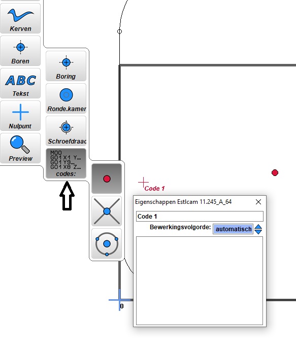
Settings menu of the cam part. He split it into two now. ![]() You can see a screenshot in my first post.
You can see a screenshot in my first post.
1 Like
Both 11 and 12 are two programs, CAM and control (default install for both 11 and 12 includes a desktop shortcut to each). The only difference with 12 is that controller setup was moved to control. Now both ‘machine project’ and ‘setup controller’ open the controller from CAM.
1 Like
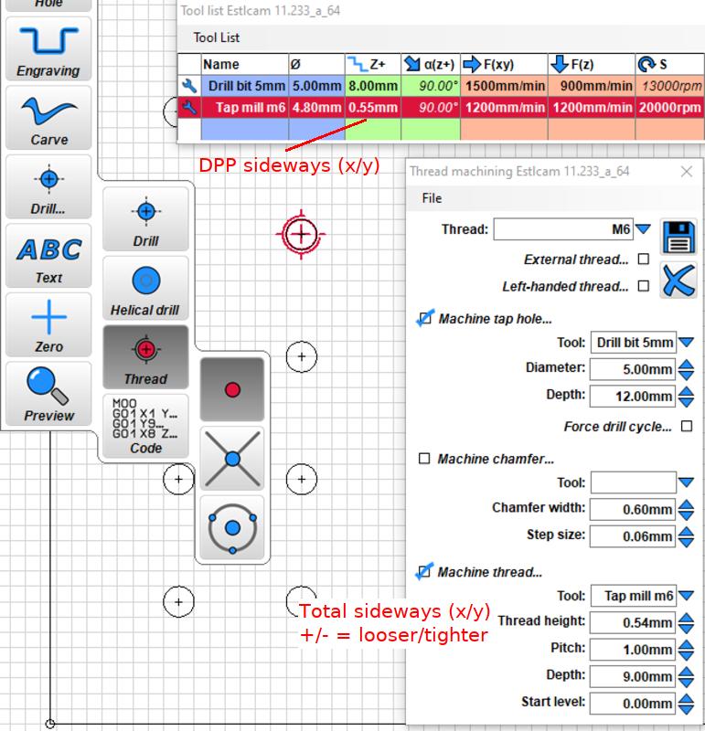
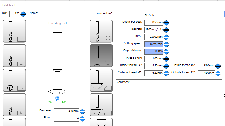
Also missing from the drill menu is the somewhat funky, but easy to use, all in one tapping window. The replacement is separate drill (/chamfer) and tapping tool paths. Tapping tool configuration is more painful without the presets (currently untested).
I don’t know what you use it for, but the drill tool configuration now allows setting a peck to full retraction ratio.
OT: Why is the forum program complaining about too many replies?
2 Likes
Hello,
I removed the code function in Version 12.
What are you using it for?
(I may add it again, but at the moment it seems like this was a quite unnecessary function and I try to keep the program lean)
Christian
8 Likes
Hey Christian, nice of you to pop in. ![]()
I have a question, if you don‘t mind: Are you planning on adding a function for V-Carve inlays, similar to F-Engrave? We now work around it by setting the starting depth at -1mm for the inlay part, for instance, but that does not work for deep inlays.
And are you maybe adding support for 5 independent motors with endstops? At the moment I am working with the OpenCNC Shield 2 that features autosquaring with an ESP32, but it would definitely be nicer to just have it in Estlcam natively. ![]()
I also agree with people who said the menus are a little small on some monitors. I think the horizontal menus were more accessible visually. But that may be subjective.
2 Likes
I am a volunteer at an open air museum and make a lot of texts on planks sawn from trees and because ignorant people have to be able to position the text in a good place, I add code before the actual milling. (google translated from dutch to english)
added:
They don’t use the control part of the program and just the generated gcode on a usb stick that is inserted into the milling machine.
1 Like
I think V-carve inlays are already possible now that negative offsets are allowed (or at least now that I know they are allowed). I just need to put together a good tutorial without any math.
Here is another idea which is probably in the advanced category:
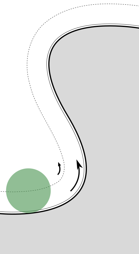
When doing a finishing pass, the feed rate defines the speed of the (center of) the tool, which can be significantly faster or slower than the speed at the cutting surface depending on the radius of curvature.
On interior corners, the speed at the cutting surface is faster, and on outside corners, the speed at the cutting surface is slower. This is most noticeable at tight inside corners where the tool will go seemingly very fast and sometimes leave a poor cut.
In this illustration the green circle is the cutting bit and the dashed line is the tool center path. The effective speed at the cutting surface is higher on the inside corner, meaning feed per tooth, material removal rate, and tool load are all higher. When the inside corner radius is just a little bit larger than the cutting radius, the loads can be much higher.
I had considered writing a python gcode post-processor to detect curvature and reduce feedrate, but I thought others could benefit from it too if it’s in the CAM processor.
At some point I am hoping to make a jigsaw puzzle where the interior curves are tight and the fit will highlight any errors. I have not tried it yet so I don’t know for a fact that it is a problem, but I have observed anomalies at inside corners before, so I am anticipating this being an issue.
4 Likes