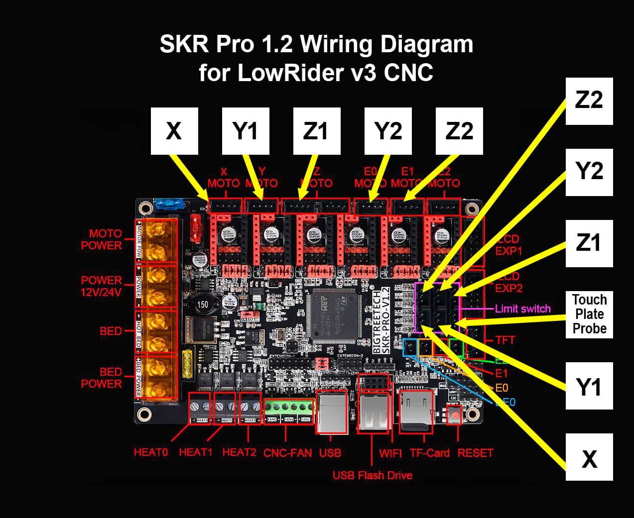
I don’t know if I am doing this right, or i am in the right area, if not sorry. I have a 4 axis xyz with another y motor called y2.
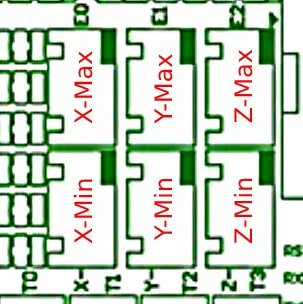
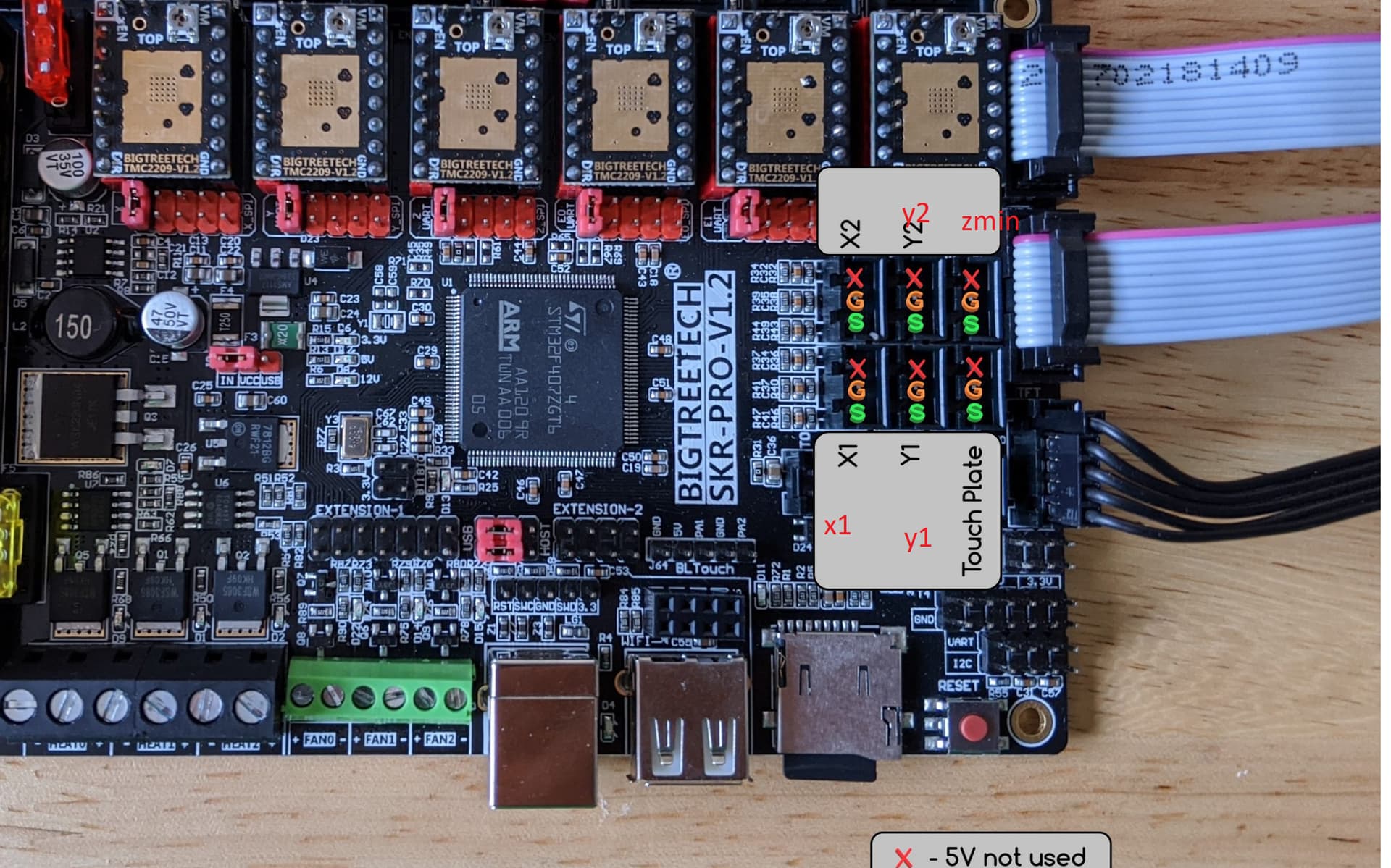
I have a btt skr pro v1.2 board in marlin how do I configure for do I make the y2. I think i am suppose to use E0. But also the end stops. I have x,y,z, and y2. How would I configure these. Also your marlin says like xmin and x max. what are these. I have 6 end stops plugs. x,y,z, e0,e1,e2. Here is what I have been looking at. I’m a little confused on this.
// Mechanical endstop with COM to ground and NC to Signal uses “false” here (most common setup).
#define X_MIN_ENDSTOP_INVERTING false // false // Set to true to invert the logic of the endstop.
#define Y_MIN_ENDSTOP_INVERTING false // false // Set to true to invert the logic of the endstop.
#define Z_MIN_ENDSTOP_INVERTING false // true // false // Set to true to invert the logic of the endstop.
#define I_MIN_ENDSTOP_INVERTING false // Set to true to invert the logic of the endstop.
#define J_MIN_ENDSTOP_INVERTING false // Set to true to invert the logic of the endstop.
#define K_MIN_ENDSTOP_INVERTING false // Set to true to invert the logic of the endstop.
#define X_MAX_ENDSTOP_INVERTING true // false // Set to true to invert the logic of the endstop.
#define Y_MAX_ENDSTOP_INVERTING false // false // Set to true to invert the logic of the endstop.
#define Z_MAX_ENDSTOP_INVERTING false // false // false // Set to true to invert the logic of the endstop.
#define I_MAX_ENDSTOP_INVERTING false // Set to true to invert the logic of the endstop.
#define J_MAX_ENDSTOP_INVERTING false // Set to true to invert the logic of the endstop.
#define K_MAX_ENDSTOP_INVERTING false // Set to true to invert the logic of the endstop.
#define Z_MIN_PROBE_ENDSTOP_INVERTING true // false // Set to true to invert the logic of the probe.