I have a question about the Emergency Stop Button. It looks like its made to plug in an extension cord but do I remove the green and/or orange plates or cut out where the prongs go?
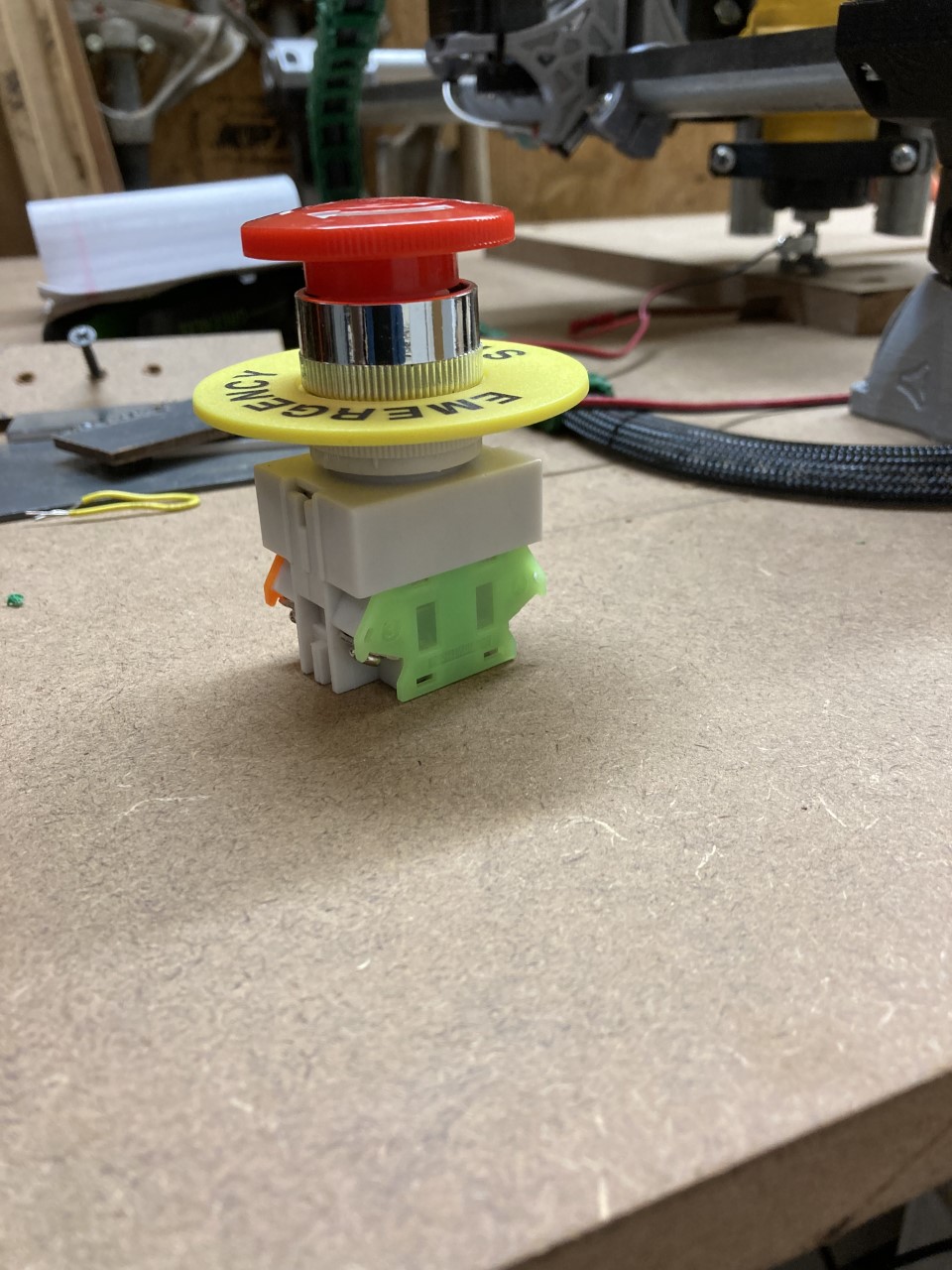
I’m guessing you do not remove those covers. That looks like a dual Contactor unit, with both nc and no contactors. Nc and no are often color coded like that; the covers likely are there for safety.
On closer examination it looks like those are windows where you can see the contacts but they match the dimensions of the prongs on a plug. I’m glad I asked before I tried plugging a cord into them. Orange is normally closed, green is normally open.
You have to cut the wire and use the screw terminals to install the switch. For MAINS use (110V US), you want the switch in a housing of some sort. I 3D printed my housing, but then I found out these endstop switches, including a housing, can be purchased on Amazon for very little $.
I agree with Robert… mains outlet plugs are not designed for continuous vibrations. Usually the estop and controller box are mounted to the Cnc table framing, which is a high vibration environment. So for safety it’s best to use crimp spade terminals with the switch screw terminals. For further safety, I recommend mounting it to a metal enclosure and bonding that enclosure to earth.
Also, if you intend to wire it like I think you plan… be sure the switch is rated at least 200% of whatever you are powering it with. So say your switch is rated 20A… don’t plug your vacuum/dust collector into it because the 10A available is already mostly used starting the router up.
The V1 shop page does not say for their switches, but most of these e-stop switches are rated to only 10A.
Yeah, I bought it from V1 as well as the steppers and its rated at 10A. I’m not sure about the steppers, there is a product number on top, KL17H248-15-4A but I doubt they pull anywhere near 4A. I think thats just part of the product #. My DW660 router is 5.0A and I wanted to connect the router and the Rambo v1.4 board to the stop switch. I don’t know if that would be pushing it or not.
I ran that combo (Makita router and Rambo board) on my old Burly MPCNC, and had no issues with my e-stop (also purchased from V1). I switched to using an IOT relay. This allows me to turn the router off at the end of the run, and the e-stop is only needs to be on the 12V input to the Rambo board.
1 Like
SAME HERE
And if I needed to go in the house I could watch the Router on Wifi Security Camera if their was a problem I could stop the job with my phone using Repeater-Server and it would also Kill router via Relay
I have a fuji estop wired to a 110VAC coil 30A/220VAC rated fuji contactor which supplies a stepper PSU, a controller+laser PSU, a dust collector, and a 220v spindle VFD. The switch has a 10A contactor, but it’s only carrying a few mA for the coil. The contactor safely and reliably covers everything that could cause a problem if left powered after an unplanned estop event… even an external plunger I can hammer on if contacts got welded. There is a 5V/3A psu for an rpi, which I wired to be always on for uploads and entertainment.
Most importantly though, every branch supplying mains is protected with a breaker, and every branch supplying DC is protected with a fuse. As long as you cover your bases with breakers/fuses well, you’ll probably be fine when something unexpected happens… regardless if you have a fancy setup or bare bones.
close older topics to help with spambots, and faster new user questions.