I can’t see how the fuse would help at all in this scenario.
Do you have a peak/hold setting? Often it’s the update of the meter and the averaging for display that’s slow, not the actual measurements. Is there any particular reason you’re not using the scope? Fast voltage measurement with time is kinda their ‘thing’…
It’ll be somewhat related to speed and total time. A freer moving Z will drop faster with higher voltages on the stepper coils and more potential for damage. A heavier Z with the same friction will do the same, etc.
I wonder about using something like a damper, given that it’s a speed issue, not a force issue? Might need some care to avoid the steppers fighting them.
So anyway, as I said above I think this is 2 separate problems that are related:
One is the bed dropping and the potential for mechanical/electrical damage as a result.
One is any axis being moved unpowered and the potential for electrical damage as a result.
There might not be ‘one true solution’ for both of those issues, but there will definitely be solutions. The electronic brake FETs are likely an easy solution for the bed dropping.
A simple shunt regulator hooked up to the input of the controller board or connected across Vmot might be all that’s needed for protecting the controllers from whatever is going on.
One slightly cunning thought is that if the stepper drivers can’t be reset out of their short circuit protection state, or if they don’t like it repeatedly being triggered, with a plug-through module like Jim suggested we could intercept the enable line and add a short delay to ensure that the FETs are off before the stepper drivers turn on. Probably as simple as an RC filter. Wouldn’t need to be much, maybe a few hundred ns?
Looking forward to a stepper extension connector board with over voltage protection
+1 for z belt holder mod and/or new spring mount parts… If there isn’t enough room to mount overhead as depicted in CrayonCad, maybe… Mount below or adjacent to z belt holder, looping spring initially up and over a new idler (wider than the spring). Spring Idler mount maybe part of new z belt holder or separate depending how far up can be placed.
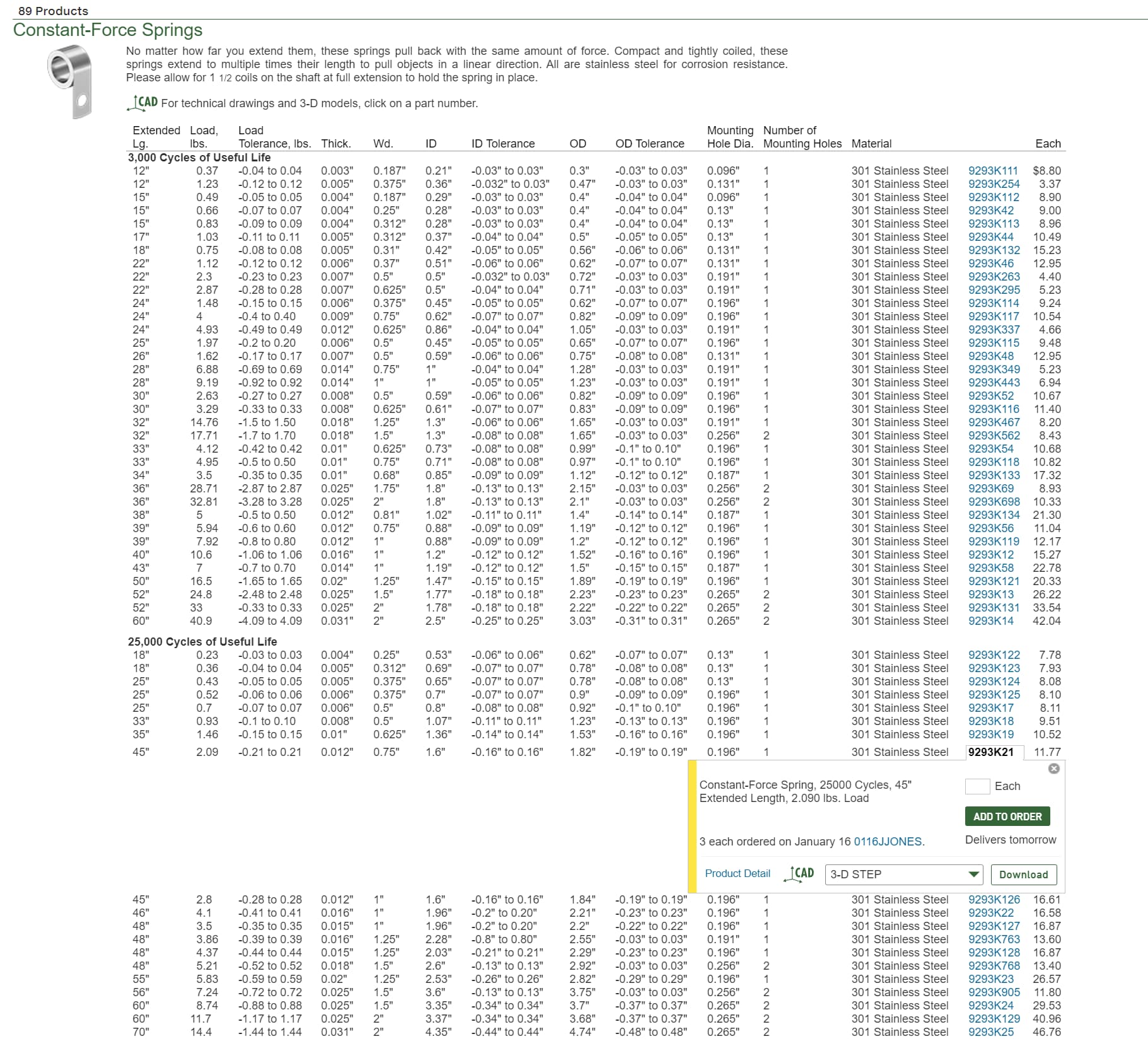
It wont give me a link to the individual part but here is the link to the page and a screen shot of the one I got. I misspoke before. They are 2.09lbs not 2.4.
This was the first thing I have ordered from McMaster Carr before. And I was very impressed. They were ordered at a little after midnight Tuesday morning and arrived here Wednesday afternoon. Better than amazon LOL
Also nice that they have the .step file to download for fusion360 as well
Yeah, that’s fair. I’d start slow and work up. The voltage is proportional to the rotational rate. In theory we can use the impedance of the coils to figure out the short-circuit current from the induced voltage, but it’s mildly annoying to do because the impedance varies with speed, so you end up with everything being exponents vs the speed and super sensitive.
I think as long as there’s a number for ‘this is roughly the speed we want’ then we can design from there.
Your scope will also have a number on the front for what the rating of the input is. It can sometimes be ambiguous between what the maximum measurement range is and what the maximum damage is. In 1MR mode (the ‘normal’ high impedance mode, as opposed to 50R mode which you won’t ever likely use) and with a 10:1 voltage probe (the normal ones that likely came with the scope) then you can probably handle a couple hundred volts. It’s pretty unlikely you’ll get there without going ham on the stepper with a battery drill or something.
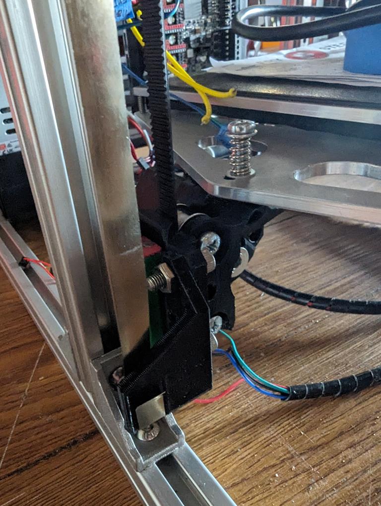
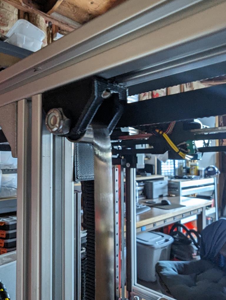
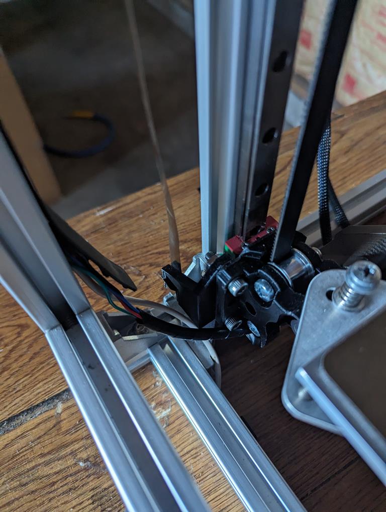
I have installed tension springs and they work great, but I’m not running the printer yet since I didn’t have time to compile Klipper firmware for my Octopus board.
Videos without https://www.youtube.com/shorts/1SWS--e2MTE and with tension springs https://youtube.com/shorts/zRqqBFRCHQc.
My bed assembly is 7.5lbs and I’ve used 3x 1.25lbs springs. I’ve modified the Z motor mounts for adding a spring brackets and mounts for 8020 frame. I can provide the files if wanted.
I wish I would have paid attention to the width more on mine. The ones I got are 19.05mm wide. @azab2c might want to look at that before you place your order.
@pavel569 thank you for the pics! That gives me something to go off of! Major help!!!
Thanks! Wondering If I switch my bottom plate out to MDF if that would be enough. I’m at 8.5 lbs ready to print now with PEI, add another 2lbs if I want to use glass
Great help. Thanks a lot. I’ve replaced my Raspberry Pi with BTT Pi board lately and their touch sensor so now I have all my HW complete and can get into it.
I just got mine set up and working in the last couple months. Also using an octopus board. All the magic is in the printer.cfg file… except when you have to add a camera and then you need crowsnest, but you can totally get up and running with just that printer file. I printed out the board pin layout and the pinout names and referred to them heavily to get things set up correctly. Happy to share the .cfg file if it would be helpful.
Man all the electronics stuff you have and you don’t have a Pi laying around? lol I’ve never tried to run it off a 2 but I know they say its possible. 2 of mine are on 3Bs and the V4 is on a 4. All work really well. I also know a lot of guys are running the BTT Pi now too
3B is perfect. Both of my Enders run on 3b’s and both have a logitech C270 camera on them. Just make sure you have a good power supply. I actually added a 5v meanwell to the V4 for the Pi, and got the usb ends and soldered wire to them for power. Never any undervolt issues. Have another one here to add to the E5+ when i tear it down