Dust collection without shoe...futile?

“threaded rod and a nut with a grub screw”…how about a threaded rod and a pair of nuts, i.e. a nut and a lock-nut ( no, not a Nylok!).

“jam nut”?

Probably. Two nuts on same thread, tightened against each other.
In UK English(at least, as I learned it) that is a nut and a lock-nut.
Jam nut makes sense, so I guess that is the US version.
( I’m American now, but started out English, and still retain much UK vocab, esp for things I don’t often discuss with other Yanks. I buy pants, but wear trousers etc., and just don’t start on auto engine parts naming :face_with_symbols_over_mouth:)

I hate when people get the boot and the bonnet mixed up.

Yup. But try to get a gudgeon pin if you don’t know it’s a wrist pin in US. And don’t ask anyone about their big end!

Looks like I got you started when you told me not to. Sorry!

2 Likes

If I guessed right, that a lock-nut / jam-nut would fix your problem, can we get the stls please?
I really want to get this printed (while I’m waiting for Primo C files from Ryan).

That’s OK. Its been so long I had to check the spelling of gudgeon, and learnt it is spelt the same as the fish!

shudder… Next you’ll be telling us the colour of your tyres is sweart with whyte sidewalls.

As for sweart, I said English, not Antique ! And whyte seems to be in current US usage, though not referencing tires/tyres ! (Colour and tyres are both correct, of course, as proven by Microsloth spoolchucker not liking them.
I think we have collected enough lexicographical dust for this thread. I still want those stls!

PM me your details and we can collaborate.

1 Like

The beauty of this design is to easily shift the boot up and down to accommodate the job at hand. With a threaded rod and a nut, well it will be very clunky to setup. I thought about maybe 3d printing a the hex part and embed a threaded insert for the grub screw, this could work.

1 Like

Ah. Now I see what you are after.
And in the pic above, with the rectangular duct, it looks like the duct is replacing the rod anyway, and providing support as well as the vacuum connection. If the duct had a set of dimples (or blind slots or similar) down the side, a sprung detent (PLA leaf spring ?) could engage it. Pull out to release/adjust.
If that is not secure/stiff enough, use bolt(s) with nice printed knobs to clamp duct. Clamp at edge of the long side of the duct so the short wall stiffens the bit you are clamping against.
Of course, this may be gibberish, since I am guessing based on what I can see in one pic! I can’t really see how the duct is held, or how shoe moves in relation to it (telescoping??).

Not sure if anyone cares with the way this thread has gone (lol, I kid!), But my little bastard dust shoe actually works pretty decent! I am pleased anyway. I’m glad I could spark some good conversation, in truth.

I may still try to upsize it a bit so I can add some acrylic and actually see the cut, as well as make a better brush, but I’m off to a good start. Thanks!

The shoe portion of the design is still very much in flux and prototype-ish, so it will be a bit before I will share the shoe. But everything else in the design is stable and works well, so I can share it now so that other can play with shoe ideas if they like the rest of the design.

Note:

  • I’ve done a bunch of cleanup and made some mods since the last time I printed this shoe, so test slices to test for fit might be in order.
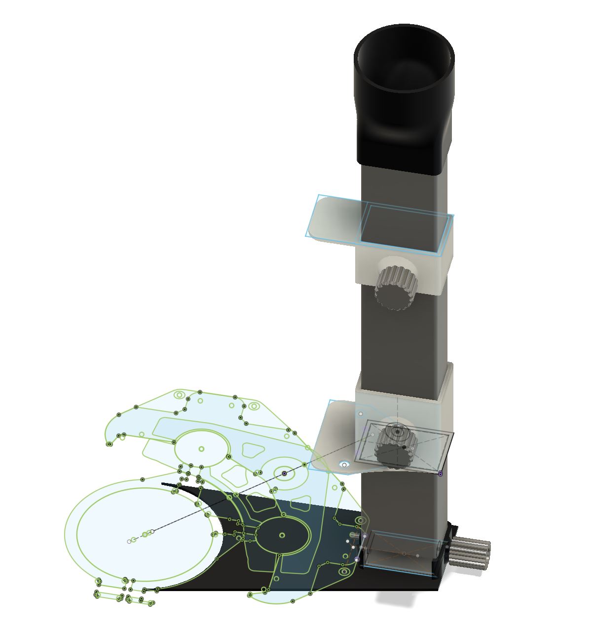
  • There are reference drawings derived from mesh slices of the Primo parts.
  • The attachment pin is a #8-32 2" machine screw where the threads have been ground off all but the upper 6mm. It was one aspect of my original design I was nervous about, but it has performed well…even when I’ve made mistakes and driven the shoe into clamps.
  • I’ve included a piece of a shoe to show how the attachment mechanism works.
  • The tube parts will print on a Prusa i3Mk3 on the diagonal. I have 135mm of working space on my Primo. Shorter working spaces can use a shorter tube.
  • I glued the brackets to the core using Barge contact cement. I though I’d go through a few designs and wanted a glue connection that I could remove, though the glue job has been plenty strong for ongoing use.

Fusion 360 file: Dust Boot Partial.zip (2.4 MB)

2 Likes

Any chance you could share your foot file. I am sure we can mount the hose to our configurations.

Sure!

These work with 1/2 loc line. I think I used #4-40 screws and nuts to fasten. Need to print two half clamps.

There are two versions, the round one I am currently using, and an oblong one that I will try next time I care to mess with it.

Also, I wasnt super happy with my bristles. I cut a thin strip of 2-liter soda bottle, and cut some paint brush bristles and glued them to the strip to make a linear brush. Then I tucked this into the round/oval undercut in the boot. It was a finicky and messy process that I didnt love, so if you come up with something better please let me know!

dust_shoe_rev2 & 3.zip (620.9 KB)

Just uploaded my take on this dust shoe for the Makita RT0700x.

Thank you for providing the base @robertbu

Pretty much every part has been changed to suit my case:

  • Dust Shoe:
    • There was none, now there is one for the Makita RT0700x with a 2mm slot for whatever you use for bristles (I print mine)
    • There are insets so as not to collide with the heads of the lower bracket bolts, saving 5mm of Z travel
  • Vacuum Tube
    • Tweaked the attachment so as not to expose the pin/M4 bolt
    • Changed dimensions due to smaller brackets
  • Brackets
    • Reduced in size to prevent a collision with the truck when at Xmax
    • Added “hooks” to integrate the top bracket with one of the bearing bolts of the core
  • Vacuum adapter
    • My shop vac has 35-36mm tubesize.
  • Bristles
    *I print mine for push fit out of TPU - still need to test them a bit more though.
1 Like

Tealfixie,
I’m looking to modify or create my own independent z-axis dust shoe for the Brutus I build (in the spirit of the MPCNC). Have you shared your design somewhere? I’m really liking your design. 1) I have some left over 8mm rods 2) I think I can make use of some linear bearings I have, and 3) it is a simpler version of what I came up with (except I forgot about my clearances and my version wont allow the machine to home in the X direction :man_facepalming: - doh!).
If you haven’t shared this or plan to, that’s ok. I’ll make use of your pictures and try to do something myself (or mod some other designs together that might work).

Z-Independent Mount.zip (2.0 MB)
I was able to dig out the old files and clean them up a bit. Here’s the fusion 360 file. Have fun and be sure to post a picture of your derivative!