Made a big code haul today to get data logging working on the device. I had it a while back, but it was outputting human readable data which was not efficient enough to output the data I needed at fast enough rates. Adding more data to the logging would prevent the steppers from getting fast enough signals which would cause them to sporadically skip steps. Soo I turned it off and haven’t gotten back to until now…
But alas, here we are. Data logging is all of a sudden a big priority. For one, it will help make the beta testing debug process go a lot smoother. But it will also help me tackle another thing that I’ve been meaning to implement for a while: Kalman filtering. I’ve reached a sort of bottleneck with the accuracy and reliability I am able to get with the current sensor setup. I am able to get within 0.5mm or so on small cuts, but when I go to bigger designs this widens significantly and gets more unreliable with sensor drift. Also, 0.5mm isn’t quite acceptable - I’d like to do better. My hope is that with a well tuned Kalman filtering model for the sensors, I should be able to reduce drift in the system and tighten up the machine’s accuracy. Also, this opens the door up for more complex sensor fusion implementation - such as adding a 9DoF IMU - to further improve accuracy and reliability. Since all of my rigid body position estimates start with an angular velocity calculation, which needs to be integrated to get orientation, a 9DoF IMU should in theory be able to give an additional absolute measurement to make this foundation a lot more secure. It would be nice not to have to add any more sensors, but if they can significantly increase accuracy and decrease drift, then it would make sense.
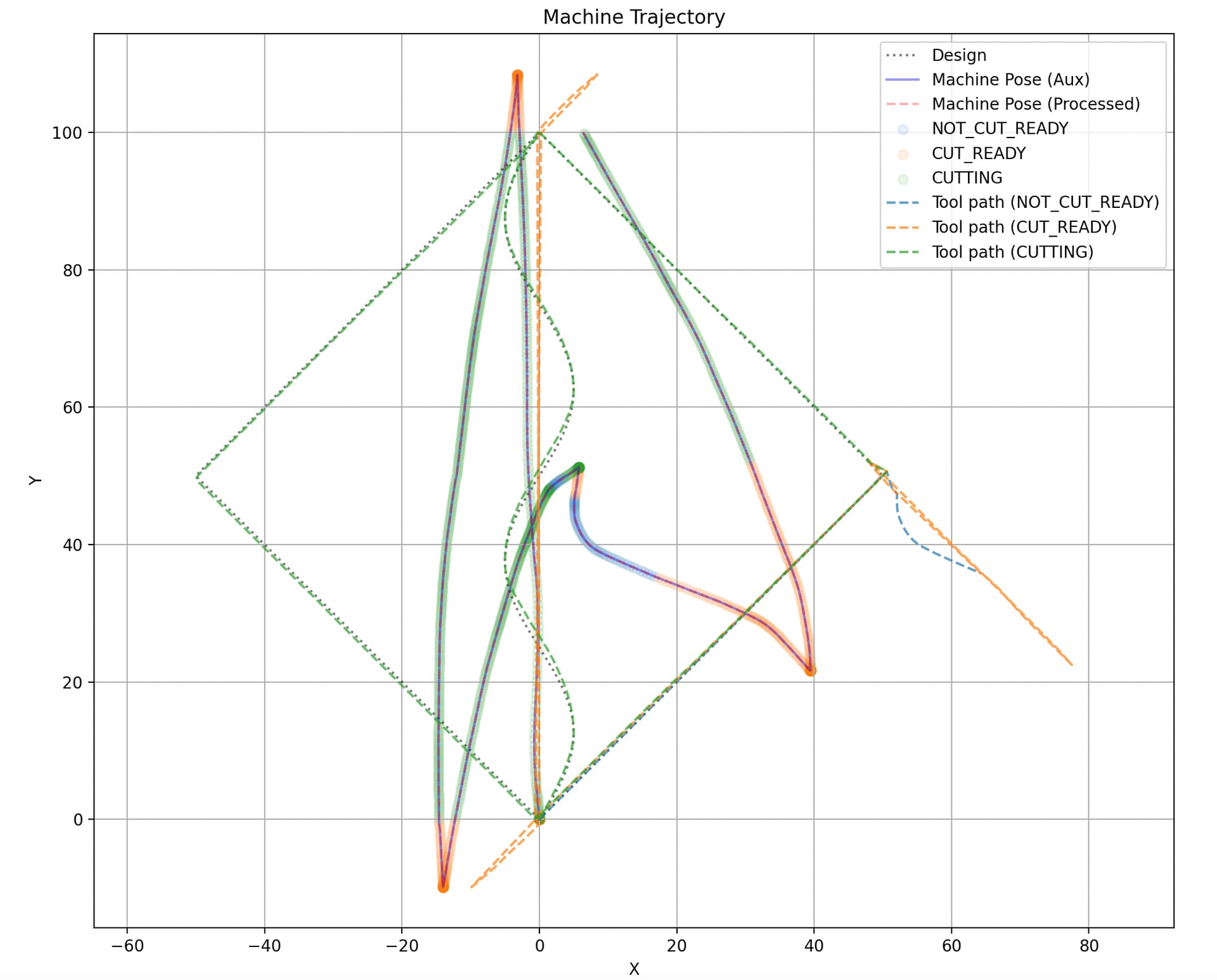
Anywho, data logging will help a lot with this since I’ll be able to easily compare what I’ve drawn/cut against what the device thinks it has drawn/cut. I can then adjust various parameters and tune the system to make these two things the same. I’ve never worked with Kalman filtering before, so this should be interesting. I’ve watched a couple YouTube videos, though, so I’m basically an expert now ![]() .. it’s pretty fun learning about this stuff.
.. it’s pretty fun learning about this stuff.
To get data logging working better, I’ve switched to binary outputs and taken the time to explicitly structure all of the data cleanly. This is how the structure looks:
Header
char firmware-version
char design-filename
Design info
int pathInfo[0] - feature type, numPoints (?), etc.
int[3] path[0].point[0] - points contain x, y, z
int[3] path[0].point[1]
⋮
int pathInfo[1]
int[3] path[1].point[0]
⋮
int[3] path[num_paths].point[num_points]
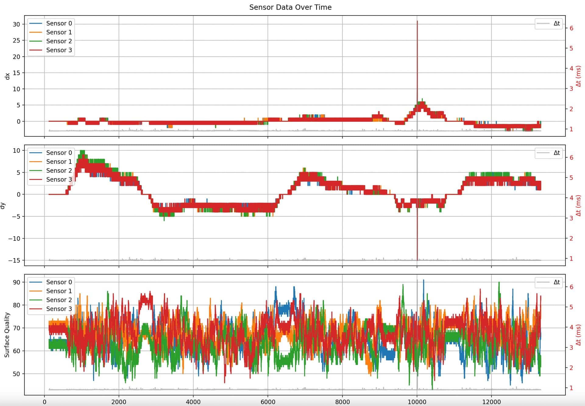
Raw sensor data
This will be sent every sensor time step
sensorPacket[4] - for each sensor
–long time - micros() from start of design
–int dx
–int dy
–byte sq - surface quality
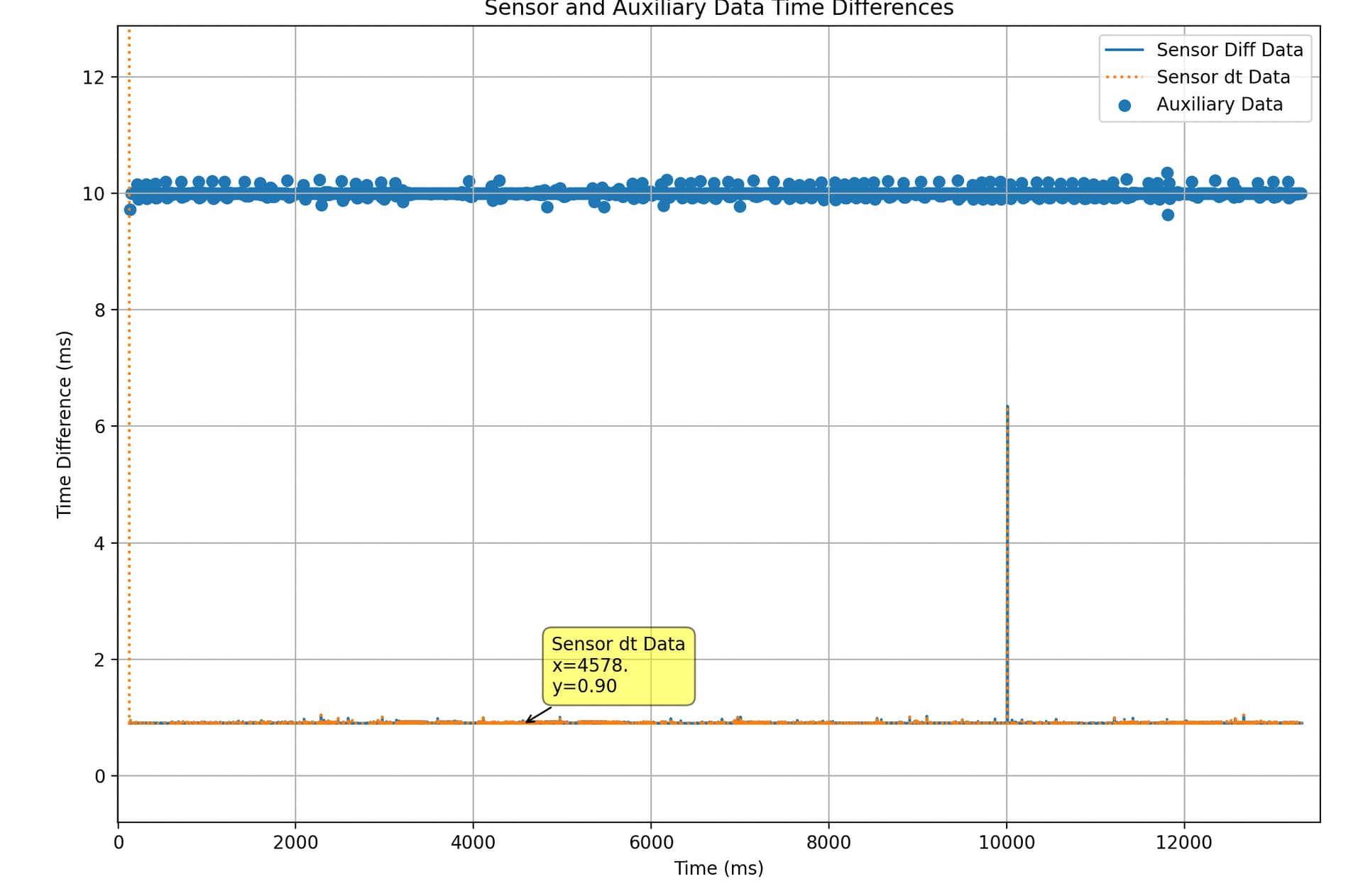
Additional data at constant sampling rate
This will be sent at a constant sampling rate
auxPacket:
long time - micros() from start of design
pose
–float x
–float y
–float yaw
int current_path_idx
int current_point_idx
goal
–float x
–float y
float toolPos
float desPos
state
–int cutState
Just finished implementing all of this into the firmware. Next step is to make the decoder and a good way to visualize the data. Will update with more progress…