So you know how you are building your machine and you start thinking of things you can do with it.
Well I have a job and I was wondering if the LR3 is capable of doing it.
I think the answer is yes, but i was wondering if the experienced people here would chime in and suggest how they would do it.
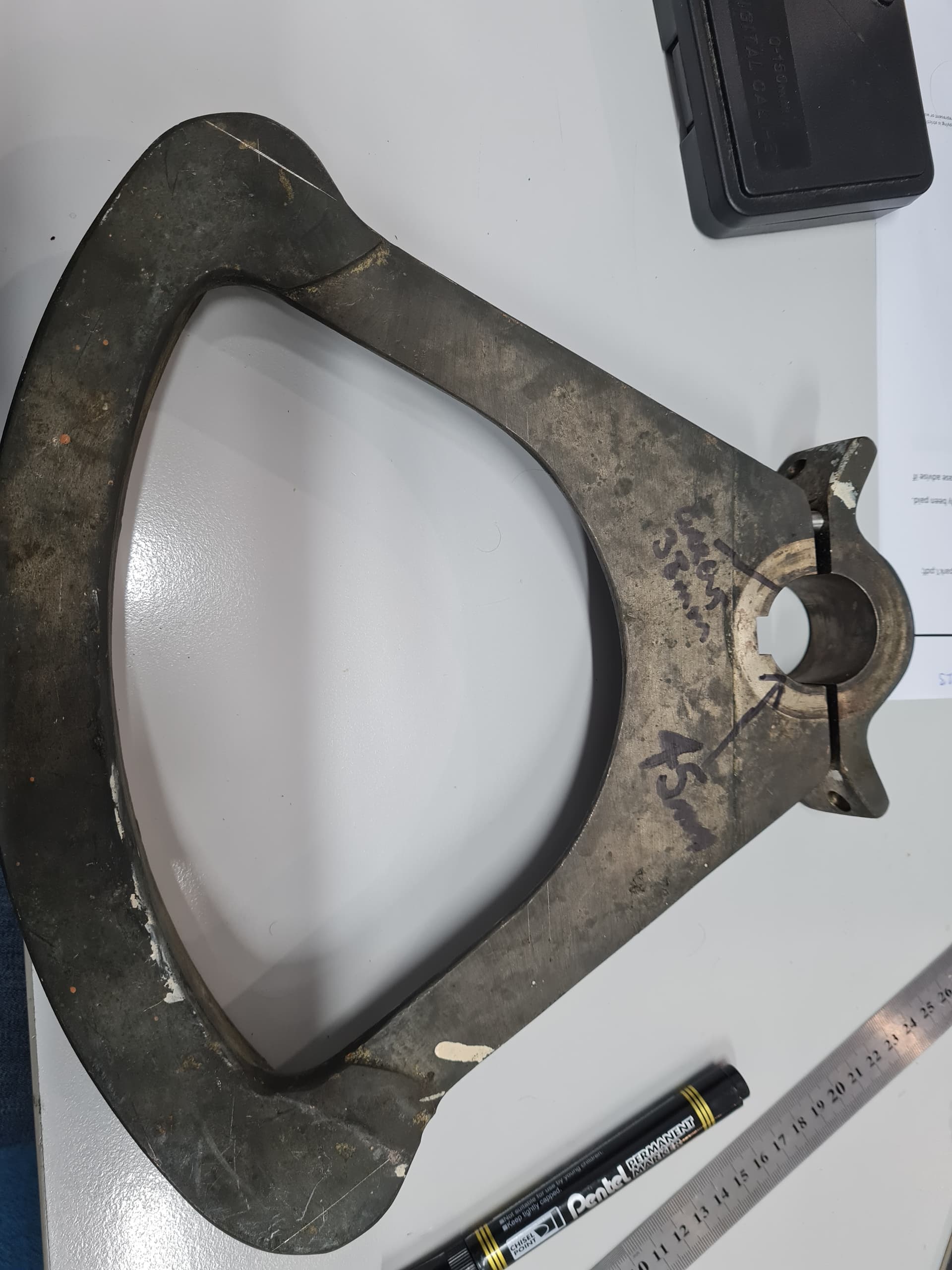
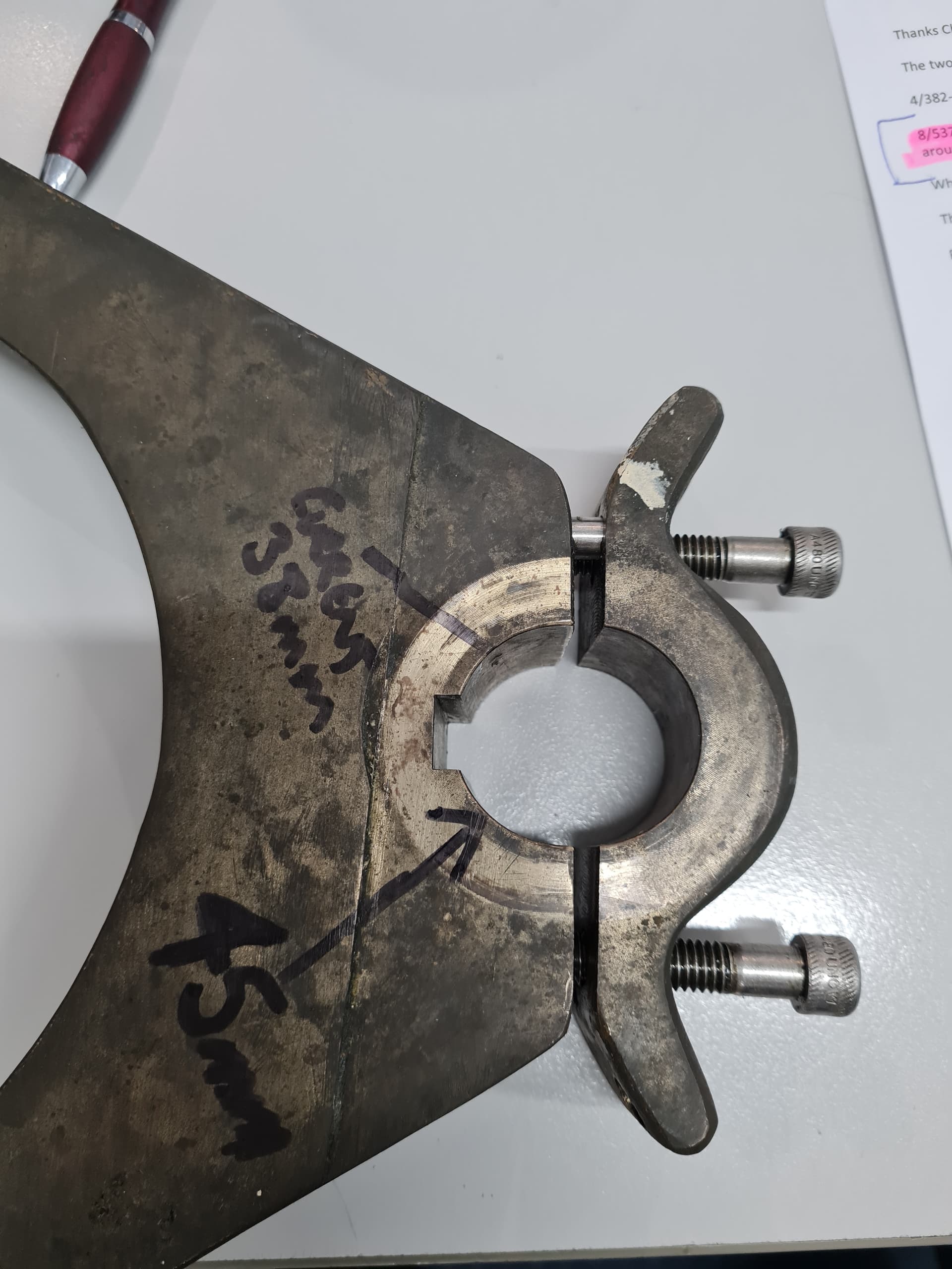
As the picture suggests the current hole is 38mm and I need it to be 45mm and the overall depth of the unit is 40mm. Also the key way is not needed for the new install as I will be drilling some grub screws into the bronze and once the shaft is marked I will drill a small hole onto the shaft to give that shear force.
So the way my brain is saying to do it is
use some smaller bolts and tightened down the CLAMP part.
Clamp down the part and find the center of the “shaft area”
Design a “donut” shape that will make the outside to 45mm and the inside of the donut to be 38mm.
Run the CUT process.
So i have several questions
Can the LR3 do 40mm deep cut? or would i need to flip it and do 2 x 20mm cuts?
If i do need to flip it, how would you do the "flip and then resetup the cut?
Would cutting bronze need some sort of bit cooling?
Yes, you could cut it with the cnc. But a better choice would be to use bore reamer. 2nd choice would be a fly cutter on a drill press or mill… A reamer will self center itself. Some automotive parts stores offer rental or loan of reamers if you don’t have or know someone with one…
thanks for those suggestions, but dont have access to that sorta of tooling and i cant imagin that it would be cheap to hire.
Please remember that this is stationary and has no up and down load to it. Also the shaft it is connecting to is not precision ground, its just mild steel, only the bearing surfaces have been sleeved with stainless.
So the diameter being a bit small and working up to 45 for a perfect fit would be my idea.
lol, I had to go google to see for sure what a steering quadent was. Ok then, have you looked at Hole drill bits? A 1 1/2 ‘’ is 38mm ; 1 5/8" is 41mm ;1 3/4" is 44mm. You can find them from $8 to $20 US. Do a test drill on a piece of metal. Hole saws can wander a bit and holes can be different is size… If you start with the 38mm, all you need to do is wedge a wood plug in the hole most of the way. Leave just enough room on one side to start the hole cutter. If you leave the center bit loose you can set the cutter in the bore hole, then connect to the drill and drill though the plug for your guide. Most likely you will have to drill from both sides. So the trick is to drill about 1/4 to 3/8" from each side. this gives you a center guide hole. Then go ahead and drill as deep as your able from each side. My choice for coolent for brass and bronze would be diesel or WD40. Then use a flap wheel abrasive to creep up to a tight fit.
I have not seen much brass. But I think it is similar to aluminum in hardness. There have been some brass projects.
How will you keep the hole open and the flap secure while milling it? I assume you don’t want to mill it while totally closed, or the final hole will not leave a gap, and there won’t be any tension. Maybe place some shims and then tighten it way down.
I have not done any metal work on my CNC. But my guess is that having the bit cut from the inside out, maybe even with very large DOC and shallow step over will let the chips fall into the middle where they can be blown or sucked out.
Have you marked out how much material will be left on that strap? Making that hole 20% bigger is going to weaken it.
Do you have a plan if this goes belly up? Is this thing precious? Because mistakes can happen.
Brass is easy to cut, in some ways easier than aluminum, but this is bronze, which I dont know much about.
If it were me I would plan on flipping it because 40mm is pretty deep.
Make (3d print) a 45mm roll pin, oversize but can be squeezed down to 45mm. About 20mm high should be good.
Place shims in the gap between the clamp parts and tighten the screws down.
Cut a 45mm pocket in your table, say 6 mm deep just for locating.
Eyeball the part to center over the 45mm pocket and clamp it down securely. Run the job to enlarge the hole to ID of 45 but only 21mm deep. Use a finishing pass to minimize the effect of deflection.
Flip it over and use the roll pin to locate the partial cut with the pocket in the table. Wiggle the part so it finds the best alignment with the pocket.
Clamp it down and run the same 21mm deep cutting job.
The pocket in the table and both cutting jobs have to be done together without losing the X/Y position of your machine, to keep everything aligned.
Even though everything should be perfect, in practice you might expect a bit of misalignment, perhaps 0.05 mm if I had to guess. I’m not sure if this is a problem for your application, but it sounds like it just has to grab securely so it should be okay. It might leave a slight bite mark on the shaft.
Neat project
Just wanted to make sure that it is straight not tapered ?
I don’t see why you couldn’t do it. Just might take time leveling mounting and finding center.
Fantastic thoughts guys, thatnks for taking thr time to write all that and the ideas. I am out and doi g this onnthe mobile, but will definitely respond tonight!
Thanks again for taking up your free time writing your responses.
Hi Jeff,
Yes, the removing of that much material will have to be looked at, I might even off centre the hole more toward teh slot, as it really wont matter that much.
As for the the plan going belly up, thanks for bringing that up and the answer is really is no. there is no other plan, well i guess the backout plan is to get it welded up, filled up and redo it.
Bronze can be mig welded, so better than nothing.
Hi Jamie,
really thanks for that detail explanation of how you would do it.
I really like this idea.
But I have couple observations
If the start point of the job to the centre of that roll pin and as everything is revolving around that centre anyway it would make sense.
Also doing it that way would make the flipping process more accurate.
On that flipping process, I would have to be careful as this is a casting there is no guarantee that the casting is symmetrical, but as the whole quadrant rotates around that 45mm hole and using the idea of the roll pin would somewhat negate that.
But a little testing with the jig would reveal that.
Hmm I hadn’t thought of the possibility that the two faces might not be parallel. In that case the second bore would not be coaxial, or even parallel with the first. The center of the second bore would be aligned with the outer face of the first bore (aligned by the table pocket) but they might not meet nicely in the middle.
Yes, in your example using a rebate it would be.
But using the cemter of the “role pin” as the machine zero, and using best effert on the rest of the casting when clamping it down would make the alingment after the flip process hard.
Infact if i figure out the exact center of the larger outside rouded face, compared to the dead center of the mounting hole i am maching and strike a line along the casting from the bore hole to the outside radius that could give me a point along that outside radius to flip against. (Still using your idea of boling down the cap with the spacers)
So then if the bore hole is one fixed point and the end of the center line is anohter (with say a bit of wood with a center line from before the flip process drawn on it so i could use that to align too) i would have a good chance to align it after the flip.
I guess the trick is after the first machining process and the flip, as my “roll pin” will be machined away, so flipping the peice I would not have anything to align againts. So if i only maxhine down 15 on the first pass and the 25 on the second, as that 5 mm (being that the part is 40mm) would give me 5mm to re-align the work peice.