Hey there, i’m currently printing parts for the primo c, and the belt tensioners are not fitting in the corner tops or bottoms, i’ve got my anycubic vyper dialed in as much as i can get it, so im guessing some of my print settings are off, can someone that has had success with the belt tensioners going in the tops and bottoms send me their cura settings, id really appreciate it, the only way i was able to get 1 belt block to fit was to scale it to 98%
I use CURA with my TAZ 5, but am still working on getting that printer dialed in.
I thought I had it in good shape, but after really starting to work on it realized it wasn’t.
My settings probably wont help you as I moved this to a .8mm nozzle.
Have you printed a really good calibration cube like this one:?
https://www.printables.com/model/15140-better-3-axis-calibration-cube
Can you attach pictures of the tensioners you are having trouble with?
Also, if you do print the BCC, measure that or better yet post pictures of your measurements of that.
i printed a 20mm test cube and it was pretty much spot on for measurements as for the tensioner here is a pic of one. It’s just a bit to tight to slide freely into the hole. to get one to freely slide in i had to print the tensioner at 98% of full size. i thought maybe i had a setting wrong in cura. i’m pretty sure the only printing instructions for the parts are the infill % and 2 or more perimeters for through hole strength.
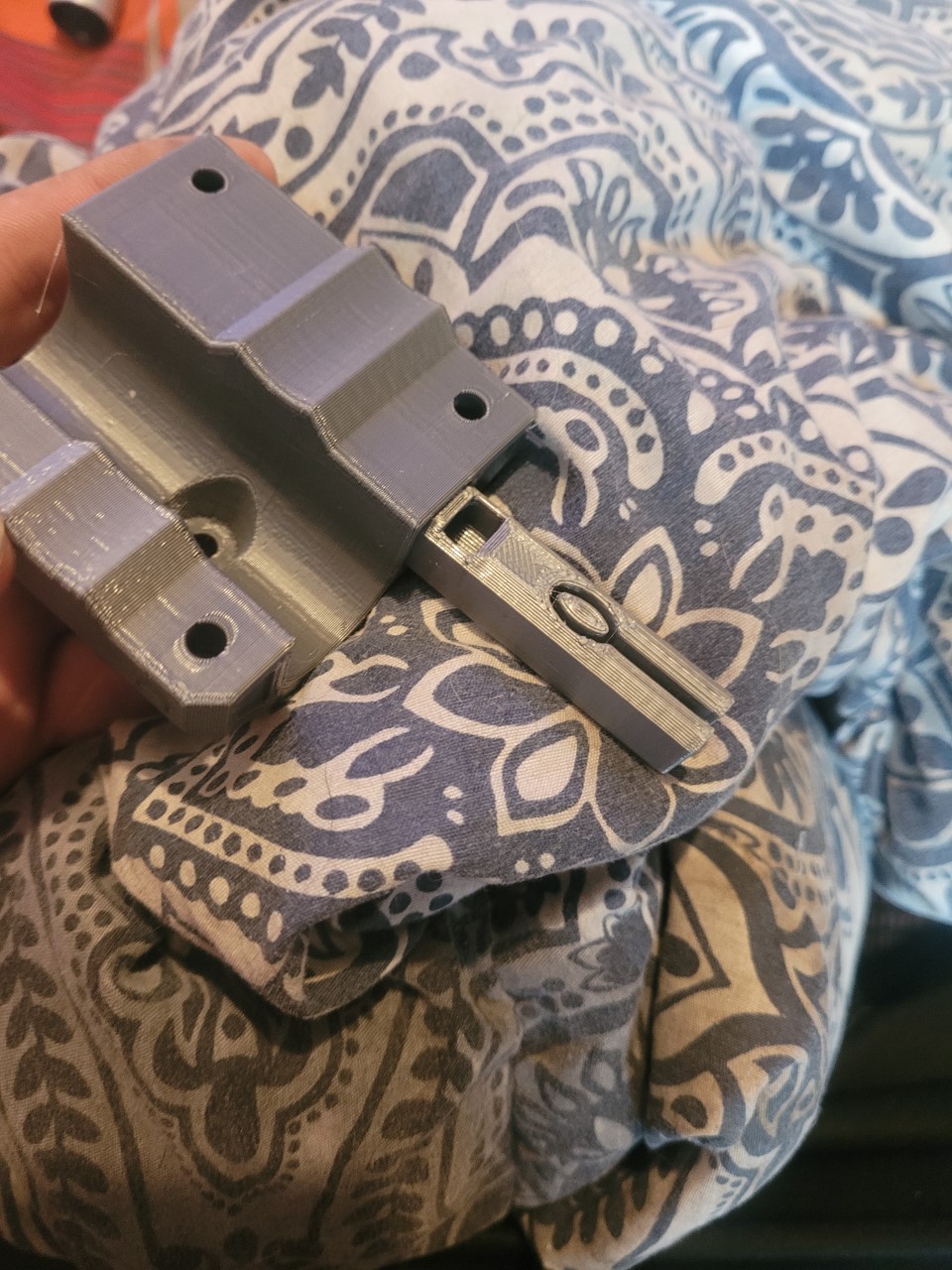
3d printers can and often do perform differently when printing inside corners vs outside corners. A cal cube is good for checking outside dims, but a peg and hole test is more appropriate for this.
Your tensioner does look a bit rough, and 98% is close, but the tensioners should actually fit with plenty of wiggle room without any sanding (ie zero binding the whole way, even with some tweaking added it should not stick at all). I personally would pause printing further cnc parts until your printer is better tuned. If it’s just a tiny bugger, that’s fine and can be sanded. OTOH if the parts are largely out of dim, that’s not going to work out well. There’s already enough to deal with when setting up a cnc with perfect parts. Last thing you want is having out of dim parts causing more problems along the way. The “cnc precision practice” starts here, at the printer… embrace it as part of the process. 
Oh, and as far as Cura settings… I use cura so can help you tune if needed, but sharing settings is no beuno in general unless the printers/filaments are literally identical. I can say I used an mostly PLA in an 0.4mm nozzle at 0.2mm layer height, 4 walls at 0.45mm line width, 2mm thick top/bottom, 45% infill… but it’s the bedlevel/speed/accel/linear advance/retract etc that make all the diff.
If the calibration cube is spot on, then I don’t think additional print settings are going to solve your problem. Maybe we are missing something here. Collect the following information and post it:
- Photo of the end view of the tensioner
- The width and the height of the tensioner as measured by calipers
- A photo of the opening for the tensioner in the corner
- A measurement of the width and height of the opening in the corner.
- A measurement of diameter of the curve used for the tubing.
Edit to add: As mentioned by Kev, your print looks a little rough. In particular I see some blobbing. Take a look at this article. It may not be the root of your issue, but you might sand the blobs off and then see if the parts fit.
the tensioner looks amazing to me it goes in about .5" but id have to jam it in the rest of the way. the printer is as calibrated as i can get it without more tools unfortunately
If you don’t already have one, get a digital caliper. Even the cheap $10 ones from Amazon or Harbor Freight will do the job.
Knowing that it goes in 1/2", I see the “zits/blobs” in this area:
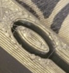
Take a piece of sandpaper and place it on a flat surface then hold your part and sand it against the sandpaper until the blobs/zits are gone. Does it solve the problem?
Next take a look in the receptacle and see if there are any zits/blobs.
This may be a print quality issue with the settings you are using for the particular filament you are using.
So with the leg lock when printed the part measures what the measurements in cura are. the only issue is the hole that the emt goes in is too small. I see something about skin expansion and hole horizontal expansion, but non of these make the hole any bigger, is there any other way to make the hole bigger without making the part bigger
Thousands of people have printed and assembled these models with only having to do a bit of cleanup. Something different is going on with your build. I just pulled the model into a CAD program and measured the socket for the conduit. It is 23.7mm in diameter. Start by measuring the socket in the leg lock to see if it is 23.7mm in diameter. If that checks out, check out your conduit. Sometimes it will flair out where it is cut. Sometimes it is not round. It should measure 23.5mm in diameter and be round. Your issue is either the printed leg lock or the conduit.
Edit: To answer your specific question, the only way I know to increase the diameter of an internal feature without increasing the size of the whole object is to edit the mesh using a program like Meshmixer, Fusion 360, or Blender.
What kind of plastic did you use. ABS actually gives a shrinkage of about 98%. I had to scale the part 1.1 times.
i use pla but i found out that i was over extruding i lowered the flow rate to 90% and temp to 195 and now its both printing beautifly and parts fit together
4 Likes
Try 100mm at least. 20.2 would show up as 101. Much easier to check for accuracy in larger parts with a larger test model.
At the same time they are tight and a touch of sanding the corners usually works.
Turns out i was over extruding big time had to lower my flow rate in cura from 100 to 94 and lower the temp from 200 to 195 it seems everything is fine now i think
2 Likes
Make sure your extruder steps are calibrated right, that is a pretty big flow adjust. But in the end if it is working it is basically the same setting.
Both extruder esteps and flow rate are dialed iin
I thought like this myself. I was wrong.
If the extruder esteps are properly calibrated, and your nozzle size is correct, you shouldn’t be needing to adjust flow rate to size parts correctly.
If in this circumstance you need to modify flow to get correct extrusion then something else is still off- slicer (Cura) settings, firmware issue, etc.
Did you calibrate esteps by a reproducible method like measuring a known quantity of filament and then extruding exactly that amount with a single extruder move?
If so, then to need to adjust flow to get correct parts means there’s still something else wrong.
Twiddling the flow rate can “fix” this for folks, but it’s still a band-aid for a misconfigured system.
In my own case, I’ve found all sorts of problems as I’ve been working to try and really tune my TAZ.
Filament was wrong in one case (2.85MM and 3MM filaments weren’t what they said they were, for example.) I now measure that filament before each job (I’ve found batches that vary across the spool enough to make a difference)
Along the way, I also found a nozzle with an oversize hole, one with a seriously non-circular hole, and one with an obstruction. I also found that single-drive hobbed bolts will clog with filament and still ‘bite’, but they don’t extrude consistently. I also found a clone V6 hotend that was set up for 2.85MM filament but had a 1.75MM nozzle (opening in the hotend side nozzle should be size of filament). This is a recipe for horribly bad and inconsistent extrusion.
I also swapped between a variety of toolheads and discovered all manners of problems with different extruders in the different tooleads. The 1.75 mm toolheads had a couple of different extruders and there are bad variations amongst these as well. Clone BMGs, for example are horribly inconsistent.
I even found thermisters from the same lot that were mislabeled where some appear to have used one type of thermistor and some a different type. Reputable supplier, but still had a problem. Result was temp I thought was good for one brand of PLA was in reality horribly wrong when printing with a toolhead with a correct thermistor.
Bottom line is that really ‘dialing in’ a printer means mathematically proving that all the systems are actually square and true and that every element behaves as your slicer and firmware believe and produce correct units in the firmware.
The proof is getting truly correct and repeatable parts (or not).
Now that you have usable prints, please keep us updated as your build progresses. I’m very interested to see your progress and to hear as you go through your assembly process.
1 Like
yes i did extruder e steps by marking filament at 100mm and then extruding 100mm and doing the math. my filament was undersized at 1.71mm, i’m getting good repeatable parts now after doing flow calculations temp tests.etc
1 Like
here is the result 0.4 nozzle with 0.4 layer height so its not the cleanest
but its a slip fit with no cleanup
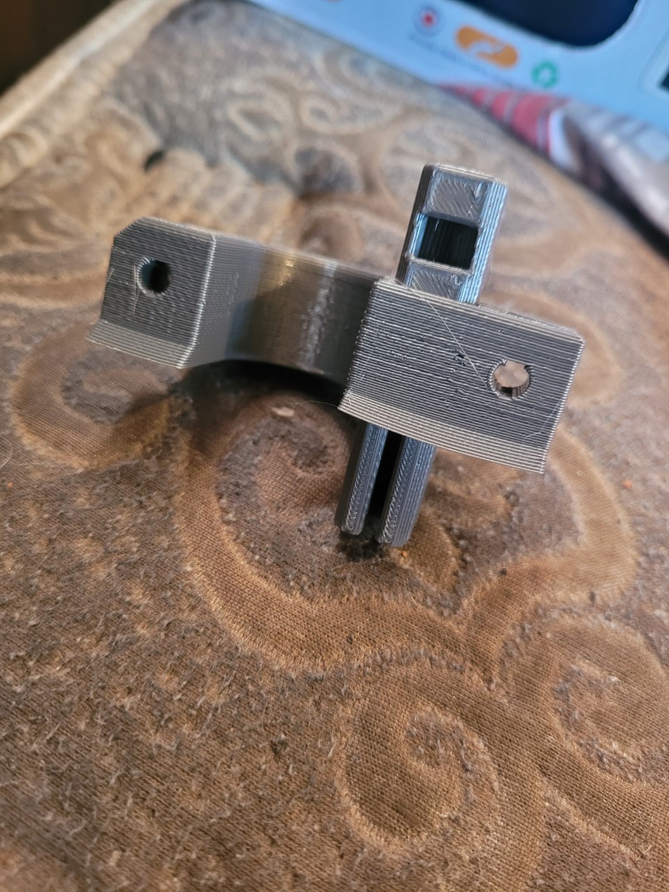
Good to see the progress!
I’ve always had troubles with layer heights >75% of my nozzle diameter so it is interesting to see you getting usable results at 100%.
Have you started printing the rest of the parts for your primo?