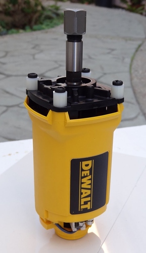
So why dont we mod the 660 and make a mount for it in this configuration?? Seems like a great way to reduce the pendulum affect a lower mount To be clear im talking about the area around the collet
Most folks don’t have the ability to thread the shaft after shortening it. It need to be done on a lathe to keep it centered, otherwise you’ll have some ugly runout on the endmills.
You can’t use a tap and die set?
But… That shaft isn’t shortened. The shroud is just removed. It looks like DeWalt stopped treating the spindle as a separate part at some point (Type 1 vs Type 2), but the diagrams look like you can take it off of the motor shaft (there’s still a hex nut-like shape down there). You might be able to shorten it (or buy a shorter replacement somewhere).
Sure, but how do you keep it centered on the shaft? If it wanders even a little bit, it’s going to cause runout.
I know, but what’s the point of taking the shroud off unless you want to shorten the shaft? Unless I’m reading the intent of the OP wrong.
Perhaps attaching to a tool mount by those 4 corners would be more rigid than wrapping around the outside of the shell that’s been removed.
That, or by having just the spindle and collet sticking out, you could lower the center of gravity of the tool, although that would also increase the lever length to the bit. Best would be if you could get your hands on a shorter spindle (assuming you have a Type 1, and/or I’m right and the Type 2’s have an undocumented, detachable spindle) that fits the DeWalt motor shaft. Of course, it’s also completely possible that the spindle is already as short as it can feasibly be, and going even shorter restricts what collets or bits you can use (unless you take the drastic measure of hollowing out the motor shaft, in which case, just thread that for your collet…).
Yeah the end intent is a combo of 2 things.
1 ease the pendulum effect by raising the mounting point but leaving shaft length alone.
2 possibly adding a longer length to z axis clearance without adding to the pendulum
[note: this contains some fairly basic info, so if you are already well-versed in CNC tuning and tweaking, please don’t be offended, I’m also putting the out here for newcomers and folks who may not have the benefit of experience with CNC machines]
Which “pendulum effect” are you trying to minimize? There are two deflections that occur in the system that are impacted by Z height and the location of the motor. One is the inertial “whiplash” caused by acceleration when the center of gravity is not coplanar with the accelerative force (i.e., the center of the gantry), and the other is the levered force applied when the bit is driven into the workpiece, which is impacted by the lever arm length from the end of the bit to the connection to the gantry.
The first only comes into play during fast moves without touching the workpiece, and can be resolved by simply waiting until the system comes to rest after stopping (or accelerating within the limits of the system to avoid deflections beyond a given tolerance). The second is what we have to deal with. It always happens when the bit hits the stock. So there is always a lever from the end of the bit to tool, then from the tool mount to the gantry, then from the gantry to the legs, and then to the table/spoilboard. We ignore most of these levers, as we either can’t do anything about them, or they’re already as good as they are going to get (or the amount of error they add is minuscule compared to the big ones). The biggest contributor that we can reasonably have impact on is the combined bit to gantry lever arm length. The way we minimize that is to keep the shaft/spindle as short as possible, and then keep the motor mount as close to the gantry as possible. This is why the suggestion is to always go with the smallest Z you can, and if you must have a larger Z axis, get shims/stands/whatever to move stock as close to your gantry as possible, so your tool isn’t dangling at the end of a fully extended Z axis all the time.
If the shroud isn’t directly supporting the shaft/spindle, then removing it has a zero effect on runout/eccentricity/etc., and you can move the mounts closer to the center of mass of the tool, which will make for a more solid mount. You can gain some (probably imagined) depth because you now have a long, narrow spindle sticking out, rather than a bulky shroud. But ultimately, you haven’t changed any of the lever lengths at all.
I actually ran my spindle this way for a little while at one point. The mount I used wasn’t the best and I had a small issue with the spindle slipping in the mount. Tool changes were a little more difficult because you had to hold two wrenches and the end mill at the same time. The cooling blew straight down on the board which helped a little with keeping dust moving around. I ended up putting the shroud back on.
+1 for real-world experience in the face of theoretical supposition.
Ran across this video on my youtube channel it shows the dewalt in the proposed configuration with a make-shift dust collector I was playing with at the time. You can see I just used some nuts to space the bolt to fill in where the old shroud was.
I remember that one! It’s posted here on the forums somewhere.
It is. I think it’s in my build thread.
