Huge thanks to Ryan, not only for all his design genius that I parroted for this, but also for releasing his table design. I worked to finish two Fusion 360 files (parametric, editable) for both a wood side rails version and a metal strut side rails version. I also completed DXF files, and two ready-to-cut, pre-arranged DXF cut plans (for a common thickness of 4’x8’ sheet goods, 23/32"). See below for details and links.
Views, info, and downloads for parametric CNC Table with Wood Side Rails and option with Metal Strut Side Rails:
Table with Wood Side Rails
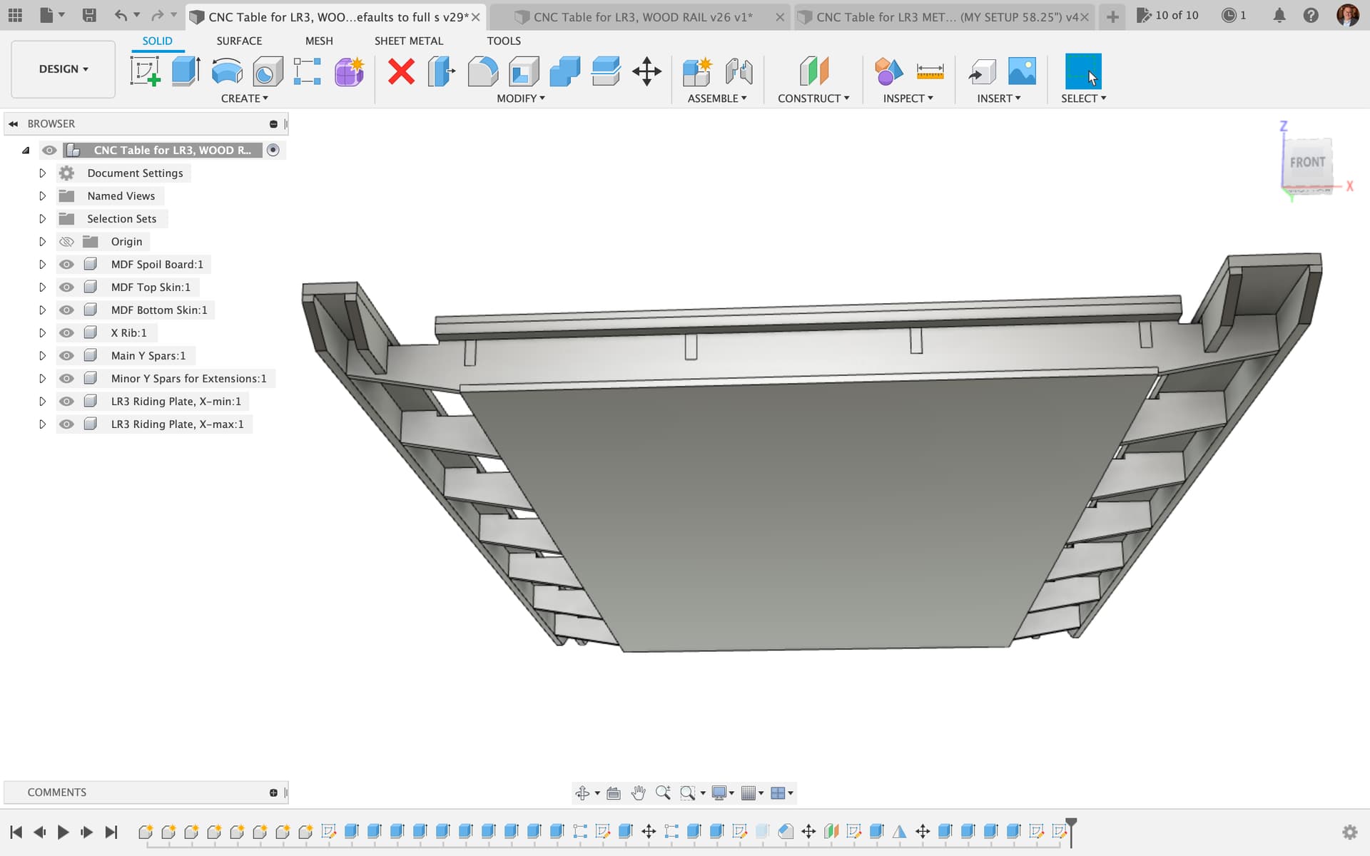
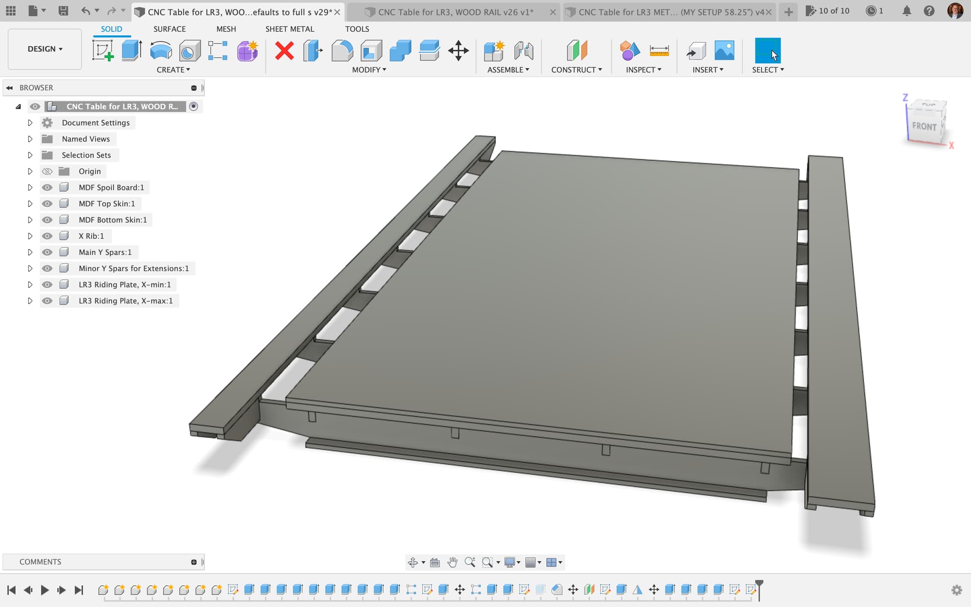
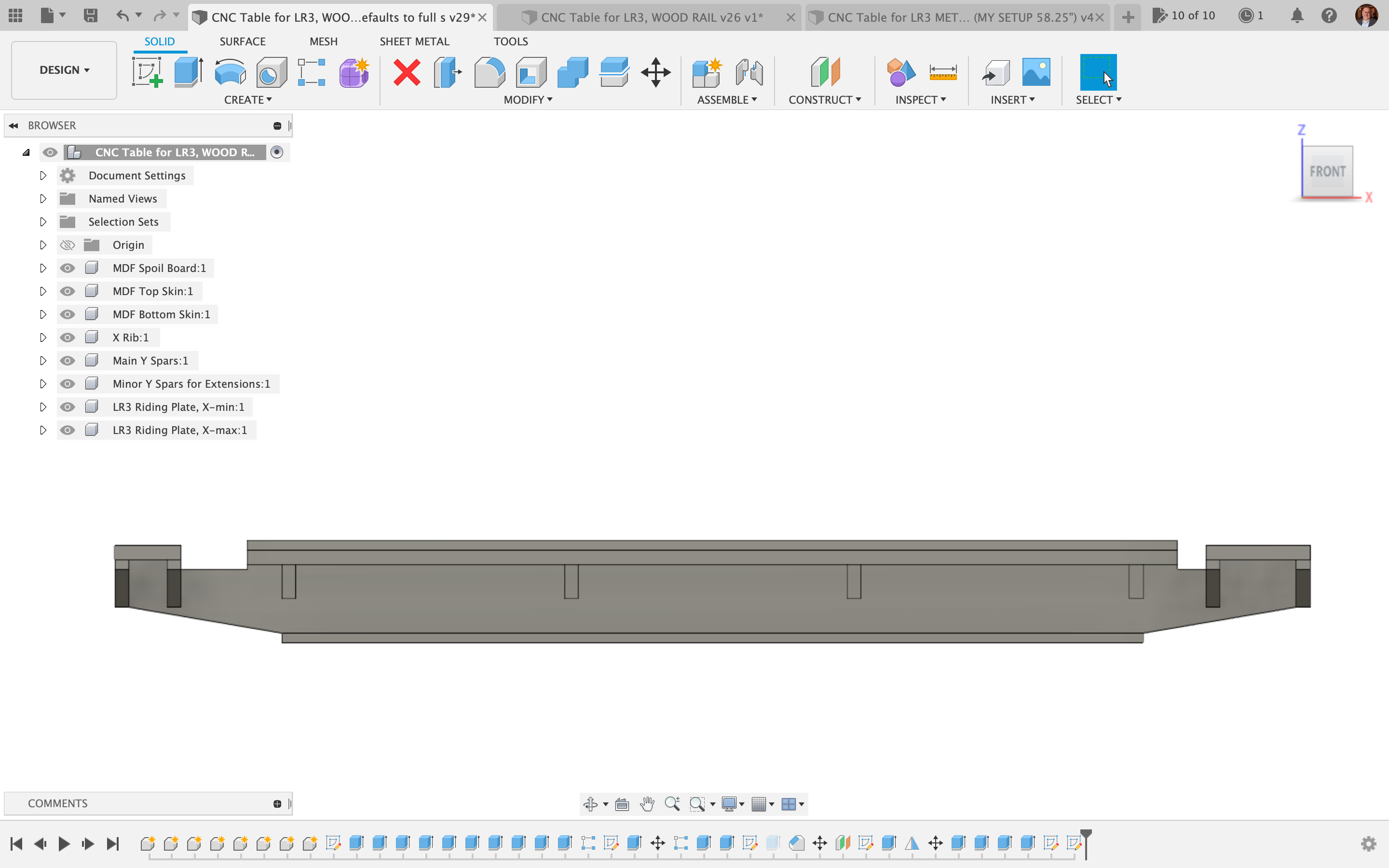
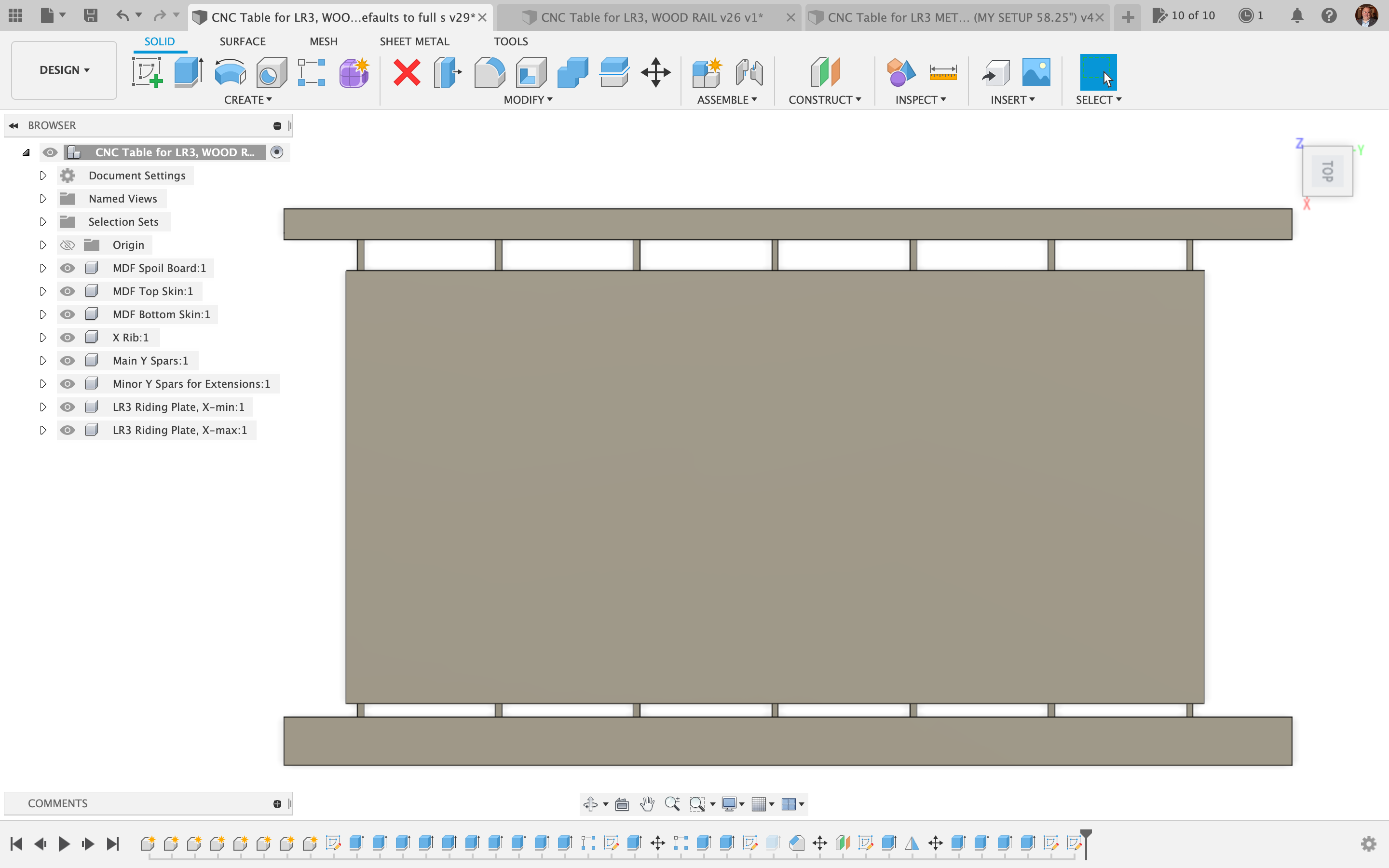
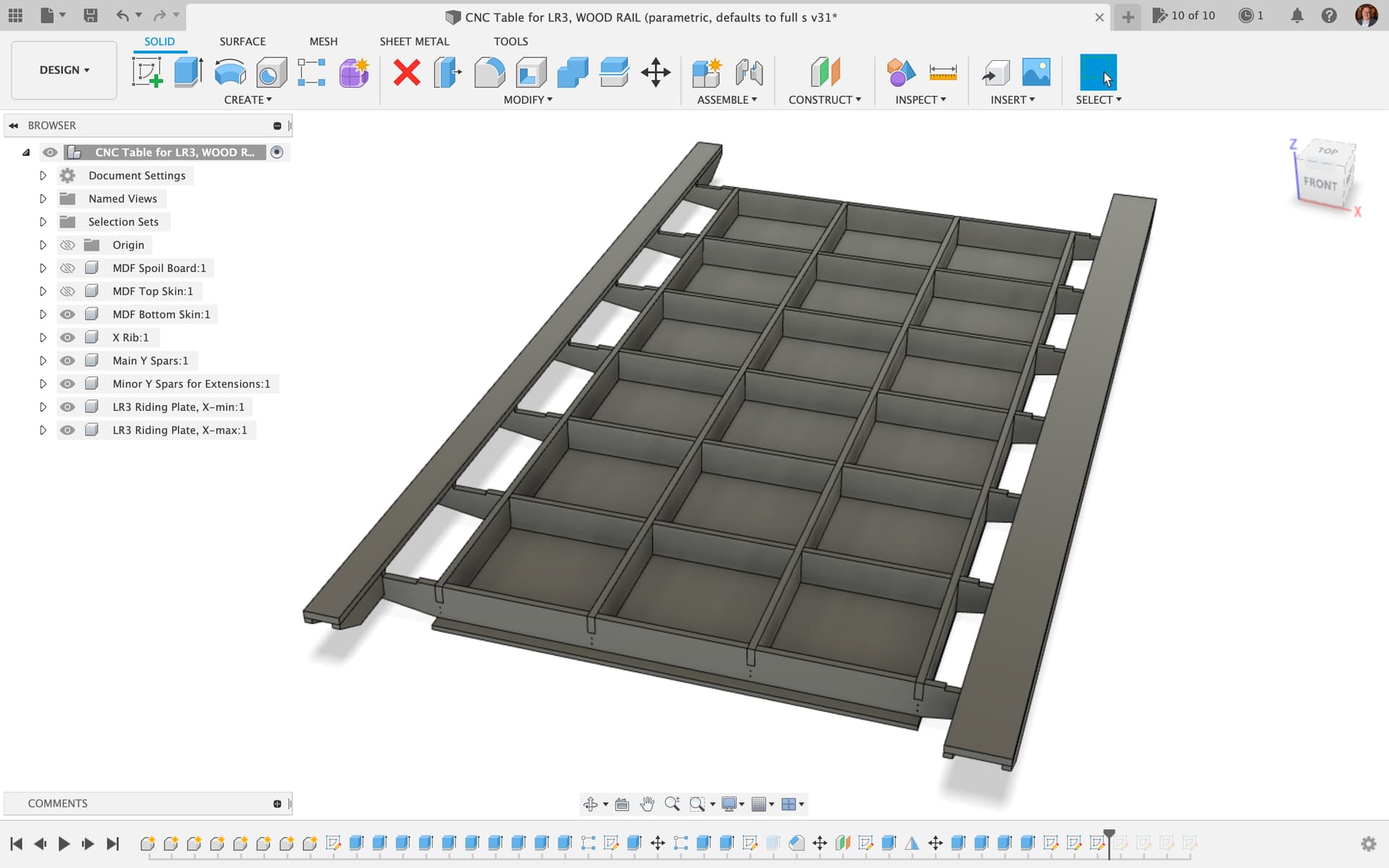
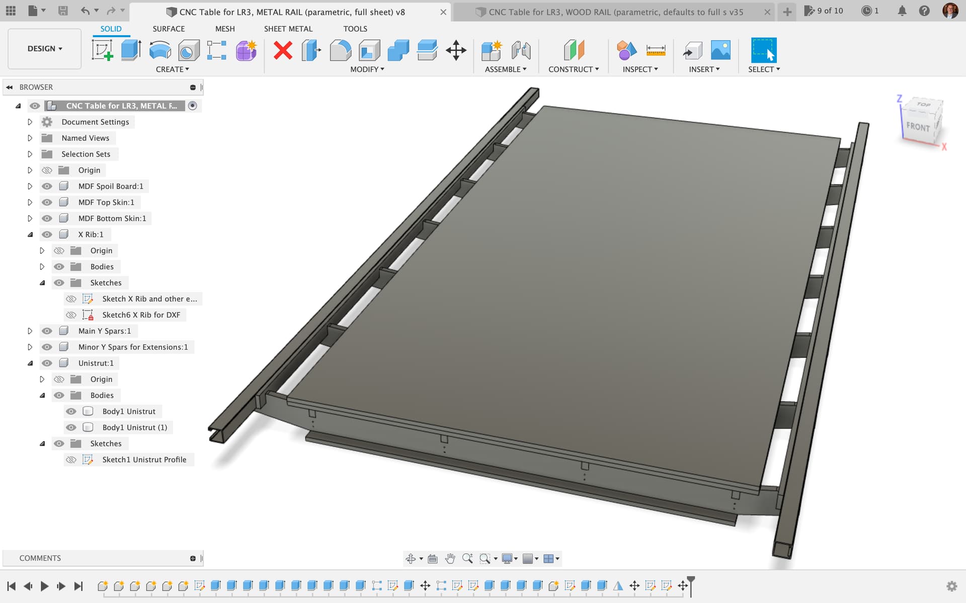
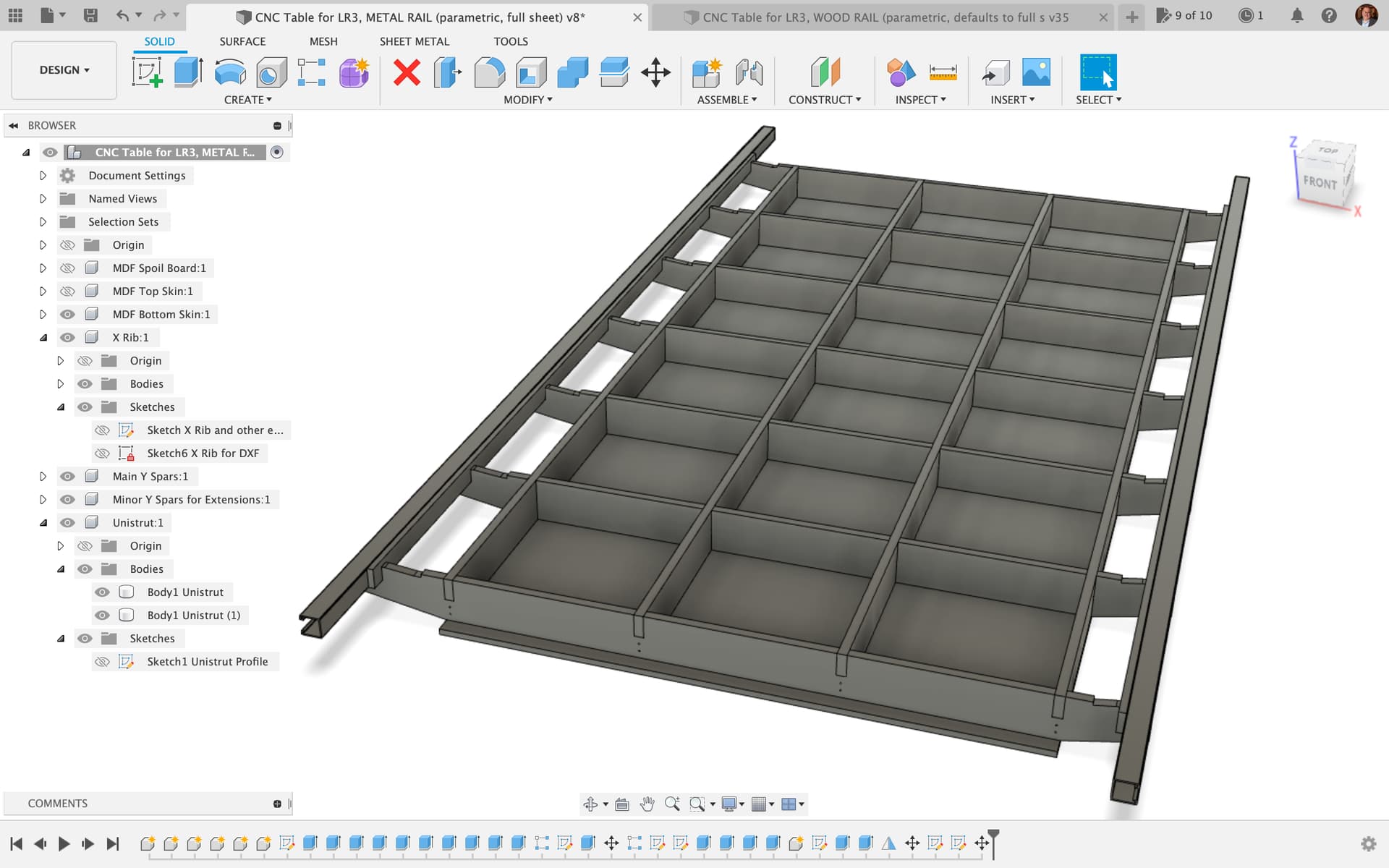
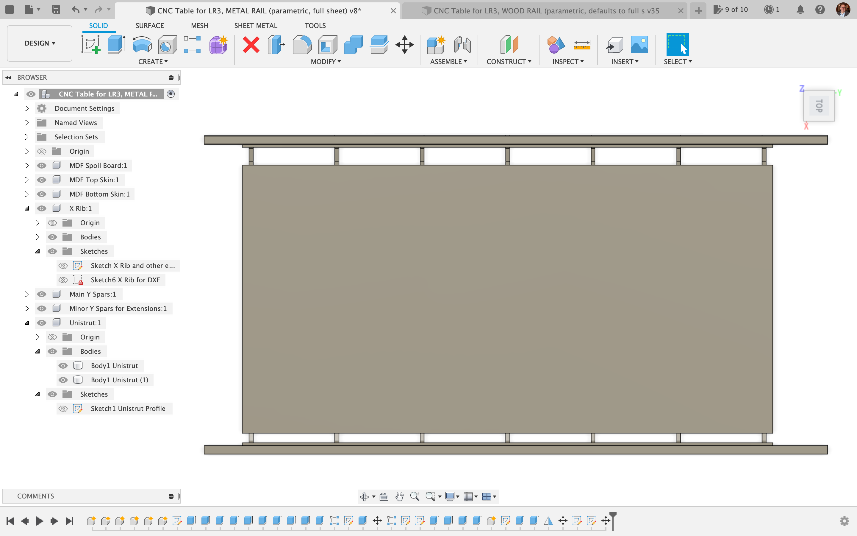
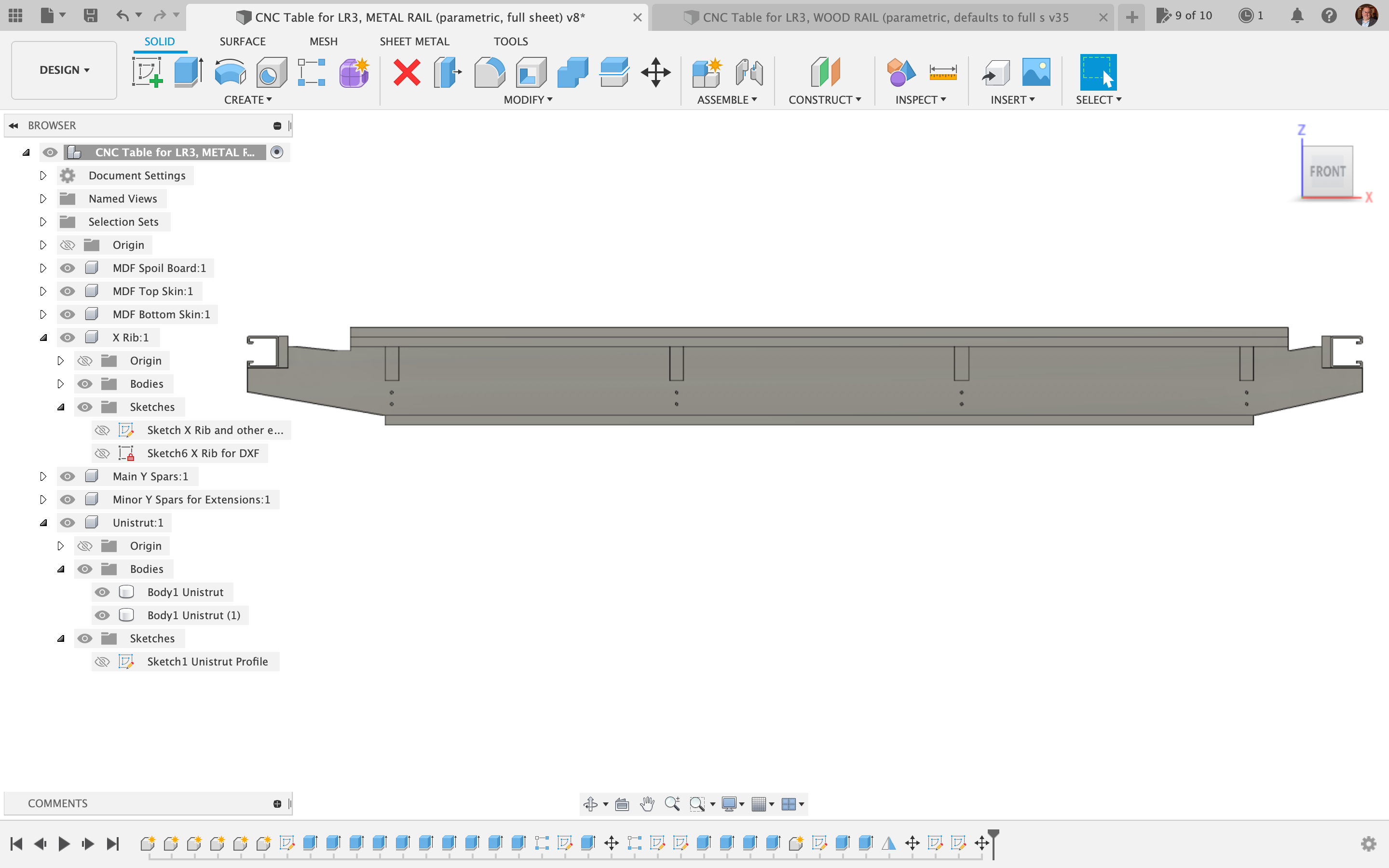
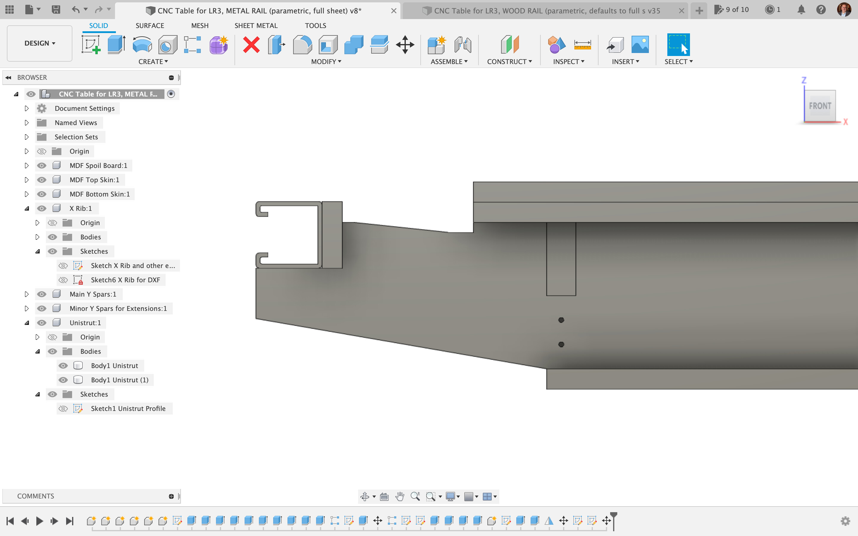
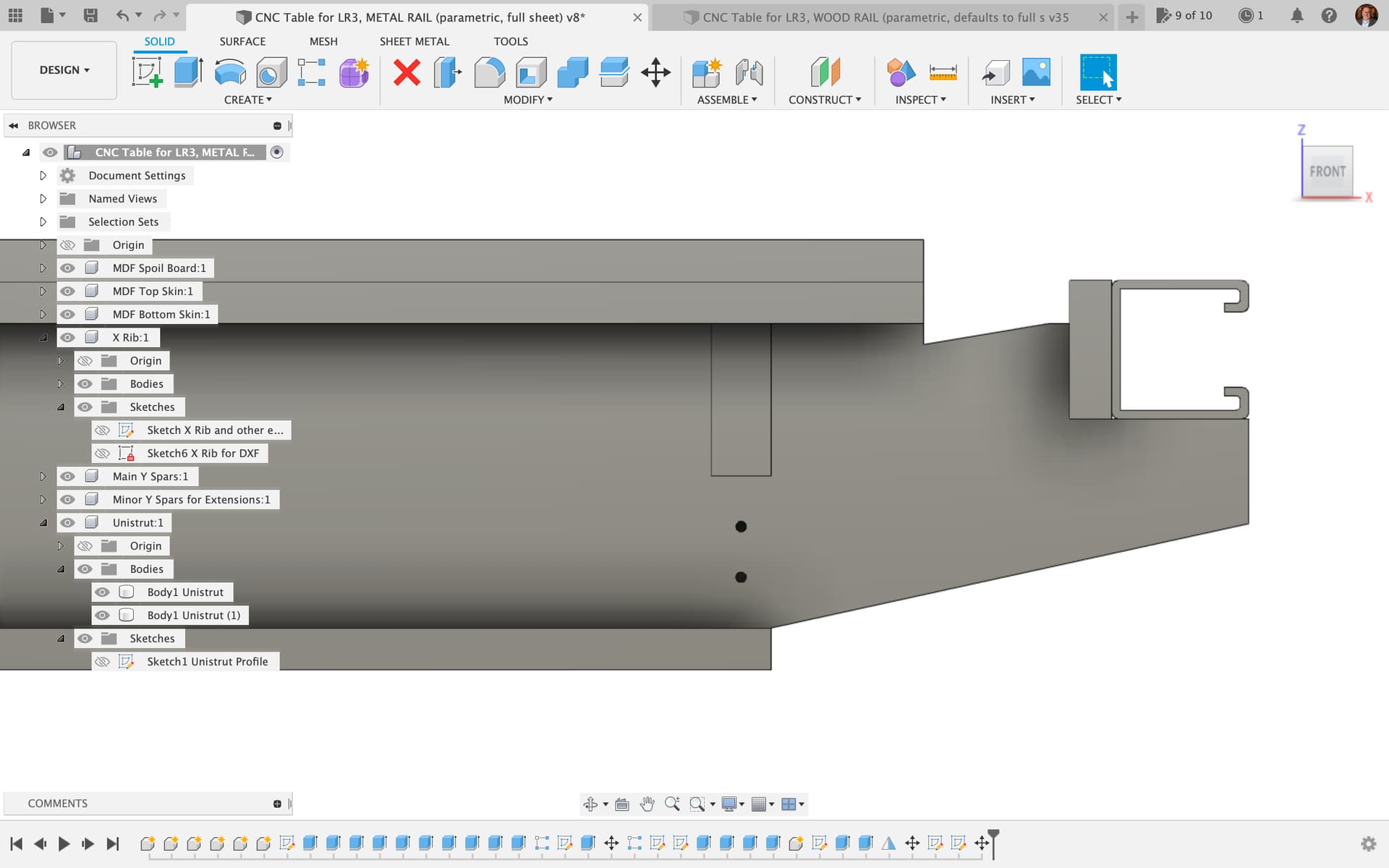
Table with Metal Strut Side Rails (aka Unistrut, aka Superstrut)
As of April 13, 2023, I have completed Fusion 360 editable parametric files for both a CNC table with wood side rails and a CNC table with metal strut side rails. Also, I have completed ready-to-cut, pre-arranged DXF cut plans (in inches, not metric) for both the wood side rails version and the metal strut side rails version.
IMPORTANT: This is all based on a common sheet good thickness of 23/32″ for the torsion box, and that can be cut from a single sheet of 4’x8′ plywood / MDF.
Please measure your plywood / MDF, and if it is different from 0.719” (18.2562 mm) thickness, then you will need to download the Fusion 360 file, edit the user parameters, and change the value of the parameter named Slot_Width. Then in each component, right-click on the sketch identified as “for DXF” in the name, and choose “Save as DXF” to export it. The only two components affected by this are the “X Ribs” and “Main Y Spars” (which together make the main body of the torsion box).

For the metal rails version, only one 4’x8′ sheet is needed for the torsion box, with off-cut strips from the MDF “bottom skin” serving as side rail supports for the metal struts.
NOTE: for the metal strut rails version, you can download and use my printable table extenders that insert into metal struts to provide endstop/tensioner support. The link is: https://www.printables.com/model/220187-lowrider-3-cnc-table-extenders-to-use-lr2-table-wi
For the wood rails version, the cut plan also includes a second sheet (of which only half is needed, so the unused part can be saved for some other project) which handles all the “long” items for the “riding plates” and the side supports for them. Any reasonable thickness of any 4’x8′ sheet good can be used for these cuts. These are set up for cutting each long part as 3 pieces that can then be glued together.
As of this current set, other thicknesses of plywood / MDF can be handled by either downloading and editing the Fusion 360 file (edit the user parameters and change the value of the third parameter, named Thickness_Plywood_Material) or make a request to me to edit and generate a new cut plan.
Note: My design plan calls for a 1/2″ thick MDF “top skin” on the torsion box, which is considered “permanent,” and then a sacrificial 1/2″ thick MDF spoil board on top of that. If you only re-surface the sacrifice layer, then the torsion box itself only has to endure maybe screw holes from attaching things, and should not need much attention when time comes to replace the spoil board. If this plan is not your cup of tea, you can edit the X Rib sketch and the resulting solid body to change the wing heights as needed.
Inspired by Ryan’s 3D “napkin sketch” illustration of a CNC-cut table for LR3…
Benefits
-
- Affordable, requiring only one (1) 4’x8′ sheet of 3/4″ plywood / MDF for the torsion box, and for the “riding plates” (also referred to as “side rails”) either a second 4’x8′ sheet, 1/2" thick (of either MDF / OSB / particle board / plywood), or two (2) 10′ metal struts (aka “superstrut,” aka “unistrut”). As of April 2023, my material cost locally for the 3/4" plywood + 2 unistruts approach is $140 (not including the 1/2" MDF sheets for bottom skin, top skin, and sacrificial spoil board layer, or screws, bolts, etc).
- Incredibly strong torsion box design, helps make the task of getting a decently flat table more within reach.
- Can be “bootstrapped” for new LowRider v3 makers who don’t yet have a table, through making a temporary cut surface by laying a spoil board “stack” on the flattest floor you have available, flanked by some boards for the LR3 to ride on, clamped to the spoil board stack.
- CNC cutting of the X ribs and Y spars helps ensure proper dimensions, ease of assembly, greater stability, and best shot at flatness.
- Compatible with my mod to protect/hide one of the long side belts. If you choose the option for metal strut side rails, my mod is ready to implement. If you choose the wooden side rails option, some remixing would be required.
Online Preview Links
Editable F360 archive file downloads…
for LR3 TABLE WITH WOOD SIDE RAILS:
-
-
- Wood Side Rails, 21/32’’ plywood (Slot_Width 0.65625’’ or 16.66875mm) 3 5/8’’ tall
- Wood Side Rails, 23/32’’ plywood (Slot_Width 0.719’’ or 18.2562mm) 3 5/8’’ tall
- Wood Side Rails, ~.75’’ plywood (specifically Slot_Width 19.15mm, or 0.75393701’‘) 3 5/8’’ tall
-
for LR3 TABLE WITH METAL STRUT SIDE RAILS:
-
-
- Metal Strut Side Rails, 21/32’’ plywood (Slot_Width 0.65625’’ or 16.66875mm) 3 5/8’’ tall
- Metal Strut Rails, 23/32’’ plywood (Slot_Width 0.719’’ or 18.2562mm) 3 5/8’’ tall
- Metal Strut Rails, ~.75’’ plywood (specifically Slot_Width 19.15mm, or 0.75393701’‘) 3 5/8’’ tall
-
DXF cut plans
for TABLE WITH WOOD SIDE RAILS:
-
-
- Wood Side Rails, 21/32’’ plywood (Slot_Width 0.65625’’ or 16.66875mm) 3 5/8’’ tall
- Wood Side Rails, 23:32” plywood (Slot_Width 0.719” or 18.2562mm) CUT PLAN
- Wood Side Rails, ~.75’’ plywood (specifically Slot_Width 19.15mm, or 0.75393701’‘) 3 5/8’’ tall
-
DXFs for TABLE WITH METAL STRUT SIDE RAILS:
-
-
- Metal Strut Side Rails, 21/32’’ plywood (Slot_Width 0.65625’’ or 16.66875mm) 3 5/8’’ tall
- Metal Strut Rails, 23/32’’ plywood (Slot_Width 0.719’’ or 18.2562mm) 3 5/8’’ tall
- Metal Strut Rails, ~.75’’ plywood (specifically Slot_Width 19.15mm, or 0.75393701’‘) 3 5/8’’ tall
-