Hi everyone!! I´m a long-time reader and now a first-time poster! I really appreciate this forum. It has been a great help to build up my V3 and to fulfill the first builds.
Now I´m facing a problem, that could probably be fixed by an experienced Gcode programmer:
I´m building skis and since last fall I´m into cutting with the Lowrider V3.
As I´m using a provided HP where a gcode is generated automatically I have to transform from inch to mm.
I´m using Repetier Host to save the gcode on an SD card to then print directly from TFT SD on the SKR Pro.
The issue is that it takes to big steps as if the machine suddenly does interpretates the steps in inches even though they are in mm. Could someone check my gcode? Is there anything else that is needed?
Thanks a lot!!
( bigmountain-base-cutout.nc                                                   )
( Generated bX MonkeXCAM v4.0.7 master@71a7aea                                 )
(   at 2025-03-07 16:09:01 UTC                                                 )
(                                                                              )
( This GCode program is provided on an "AS IS" BASIS WITHOUT WARRANTIES OR     )
( CONDITIONS OF ANX KIND, either eYpress or implied. You should inspect this   )
( program very carefully to confirm you understand its operation. YOU ARE      )
( RESPONSIBLE FOR ENSURING THIS PROGRAM WILL NOT DAMAGE YOUR MACHINE OR        )
( MATERIALS.                                                                   )
(                                                                              )
( Rapid height: 0.2500" [0.6350cm]                                           )
( * Tool: T1, Quarter Inch Straight, diameter 0.2322" [0.5899cm]               )
( * Height baseline [Z=0.0] is the top of the table.                           )
( * YX origin is the left side of the table, X is center of the part.          )
( * Requires G54 to be the part work coordinate offsets [WCO]. [0, 0] is the   )
(   center of the nose, with the board extending to positive Y The cutter max )
(   move to negative values of x                                              )
( * Requires G55 to be the machine WCO, with Z above the rapid height.         )
( * Units are mm     )
( * Center of the board in G54:                                                )
(     Y= 1002.4999X=0.0000 Z=0.0000                                              )
( * Cutter bounding boY in G54:                                                )
(     Y-0.9448799999999998 X-71.69658 Z-0.254 to Y1882.94772 X71.69658 Z6.35                   )

G90G21G17G40G49
G43H1T1
G00G54Y0X0Z6.35

G00Y-0.9448799999999998X-0.11176Z6.35
M03
G04P5
G01Y-0.9448799999999998X-0.11176Z-0.254F2032
G01Y-0.86868X-2.09042Z-0.254
G01Y-0.8509X-2.32156Z-0.254
G01Y-0.6223X-4.2672Z-0.254
G01Y-0.5867399999999999X-4.495799999999999Z-0.254
G01Y-0.19558X-6.4668399999999995Z-0.254
G01Y-0.14223999999999998X-6.687819999999999Z-0.254
G01Y0.40386X-8.65124Z-0.254
G01Y0.47498X-8.867140000000001Z-0.254
Does the big jumps happen just at the beginning, or does it happen regularly throughout the job? Could you use the upload button on the ribbon bar and upload the entire g-code file.
In looking at the file I see a number of things that are out of the ordinary. I assume you are using the Jackpot board, so there may be things the Jackpot/FluidNC handles or doesn’t handle compared to Marlin.
First there are sections without newlines and may be an issue. I belive Marlin would choke on this. For example this line: G90G21G17G40G49 I would normally see that as separate lines:
G90
G21
G17
G40
G49
Not only are they not on their own lines, but some of these g-code don’t exist for both FluidNC and Marlin. Another problem is the line “G00G54Y0X0Z6.35”. That should be two separate lines, plus I don’t believe that is how workspaces are handled in either FluidNC nor Marlin. If you are only seeing one big jump at the beginning, then the workspace issues may be the root cause.
As for the workspace, you can probably just setup your job so that the nose of the board is the machine space origine and eliminate workspace coordinates in the g-code.
Looking at the actual g-code, movement is very small. That is the opposite of the issue you are having. In the provided section, Y moves less that 1mm, and X moves about 8mm. This may not be an issue. I’d have to see the rest of the g-code.
Another potential issue is the number of decimal places. It is possible the parser is choking on so many digits.
I suspect the g-code is being generated for a specific machine, and that is neither Marlin nor FluidNC. Assuming the actual coordinates are accurate and in millimeters, and that the parser can handle so many digits of percision, you can get this code working by replacing the header lines with something appropriate for your machine.
Hi Robert,
first of all: thank you for your quick response!
I don´t get into the build at all as the first movement is slamming the tool on the table on the z axis. so I always have to abort before this happens.
I´m using the Marlin and SKR Pro build for the Lowrider V3 all stock from the V1 Shop.
I don´t know for which CNC machine the Gcode is programmed as it is an open source on Github but it is made in JSON format.
I’m not sure what you mean by “provided HP”, but whatever you are using to create the gcode is not producing valid Marlin gcode.
Estlcam is the “go to” CAM program for most users here, and using that will greatly assist in us being able to troubleshoot issues (and may cure all of your problems without further assistance)
here is the full gcode. I allready tried to change your first Ideas but sadly it didn´t change anything regarding the issue. Probably I look at it in a too easy way!! thanks for your help and for beeing understanding in my lack of knowledge!!
hi, thanks for the tip regarding estlcam! I opend the original file (attached, inches instead of mm, and x, y axis swapped)
are the red marked lines “false”?
I know its much to ask but it would be great for my usage if there could be a way of using the program MonkeyCAM as it´s generating 10 different gcodes for a whole skibuild by just entering 5-6 different numbers of the skidesign. But I understand that maybe this isn´t working out for me!
fingers crossed!!
You will want the origin (0,0,0) to be set at the top of the stock at the tip of the ski.
Another, maybe better, solution would be to get an SVG and author the milling in another program like Estlcam. This gives you many features like depth of cut. If the the progam you use to design the ski does not support export of SVG or DXF files, there are programs that will take g-code and make an SVG or a DXF. Here is a link to one. This is not a signed executable, so you run it at your own risk, but I just ran it on my machine, and it worked fine. I seleted G-Code_Ripper-0.23_win.zip from the downloads, and you have to select Export (DXF, CSV) from the operations.
Oh, forgot to mention, the feedrate is high for anything but foam. The feedrate is 2032mm per minute.
That name is unfortunate because there is a different thing that comes up first when I search for monkeycam…
But now I see what is happening. They are assuming a lot about the machine that is running the gcode. Marlin (and pretty much any firmware) has to make some assumptions about gcode and they are not created equal.
What they are trying to do here is use workspace coordinates (G54). And machine coordinates (G55). When you see G00 G54, that is supposed to be in workspace coordinates. G00 G55 is a command in machine coordinates.
They say explicitly in the header that Z=0 is the top of the table, but cut at -0.01" (-0.254mm).
hi,
thanks alot for all the help!
Yes the table is set as z=0. But to not destroy anything I always try the codes with z=0 higher up on the machine, but it still just went through z axis past the table.
Yes I post processed to change x and y.
On Nc viewer I could run the code to see if it would move in right directions.
I´m sorry to bother you all with maybe stupid questions or approaches!!
What are you using for a post processor that swaps the axis and converts the values to mm?
I agree with robert that replacing all the junk at the start with something simpler would help us narrow down any issues in the later gcode vs just the header.
I suspect there is junk at the bottom too. I didn’t open your zip because I am on my phone ATM.
thank you all for your comments and it helped me in the workflow to be able to use but change the gcodes made by MonkeyCAM.
Sorry that it seems like I didn’t care but changing the Workflow has been time consuming!
Any how I think I’ve found the issue! The Z axis was not on 0 when I selected my starting point. I now went into MArlin-Mode on the TFT an did the positioning there with “reset all coordinates”. I then went back to the TFT mode and started different gcodes. ALL WORKED!!
Would there be a way to reset the coordinates in the TFT Mode?
I’ll post some results when I’m confident that everything works!
Thanks all for your help. I´ve solved the issue uptop but I have abother question regarding the “same” gcode.
Hi, I´ve got this gcode ready but it shows only one pass from 15.24 mm down to 2mm. I would like to take it more slowly and have multiple passes at 2mm per pass to then reach the endproduct. Is this done by settings on SKR Pro (Marlin) or do I´ve to rewrite the gcode with multiple passes?
So for better understanding, the gcode attached shows the endproduct.
typically the cam program will have a step size that sets the depth of each pass. If you don’t have that, you can copy the gcode and find/replace all the Z commands in the part you copy to be the intermediate depth you want.
this is how I would do it…
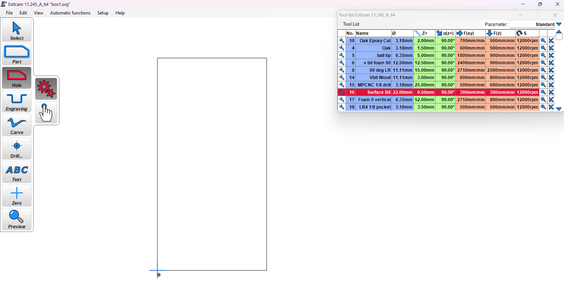
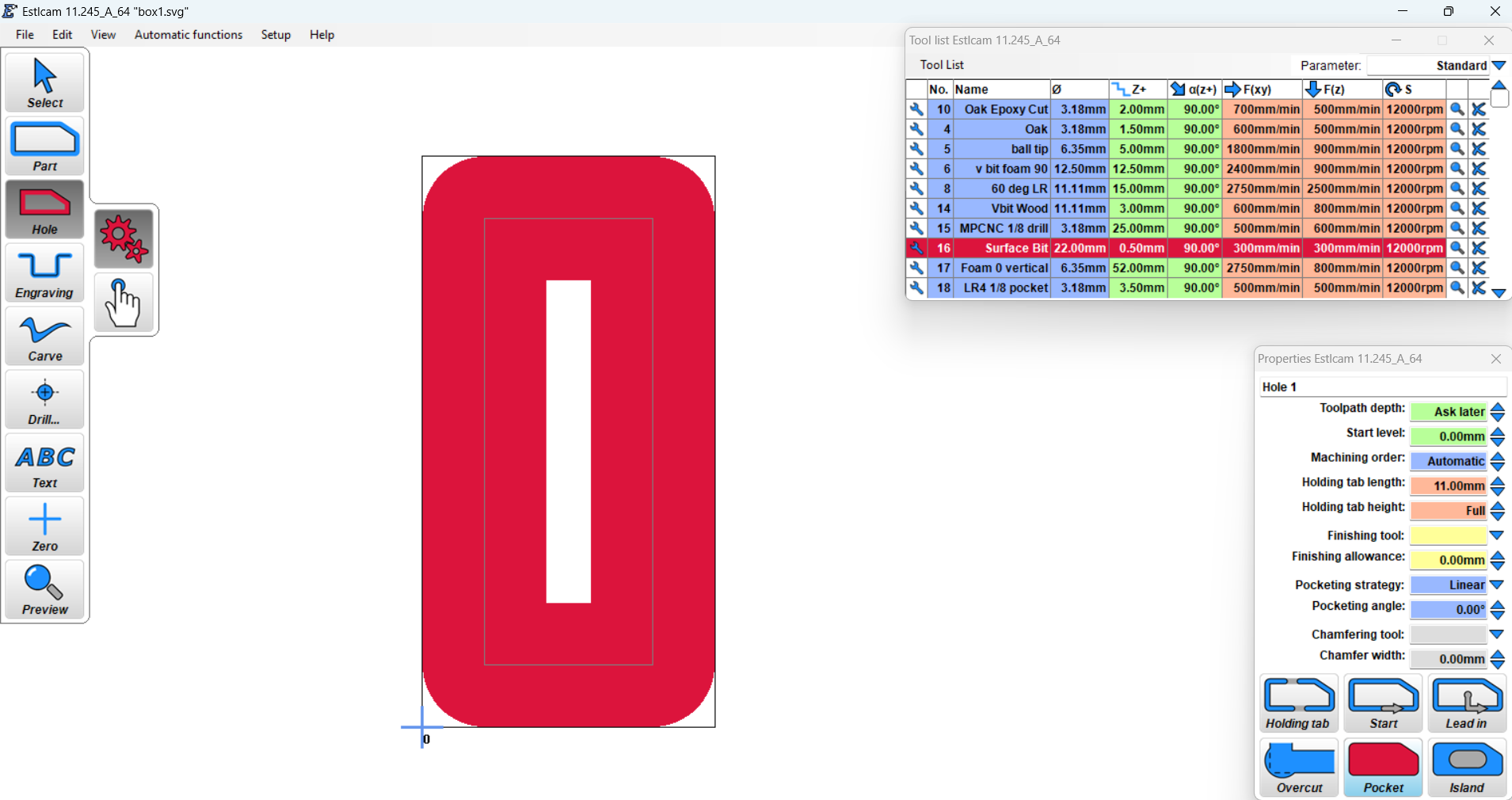
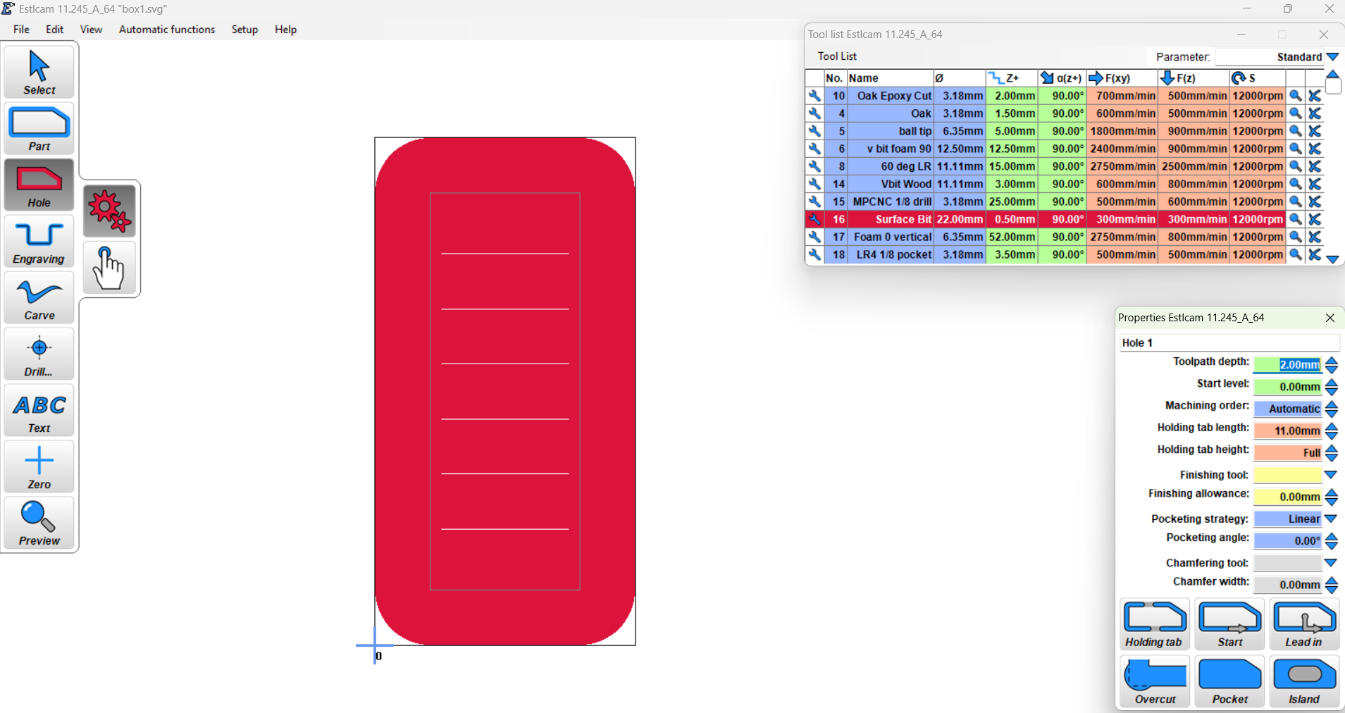
for example… a box / rectangle:
If you wanted to manually change the number of steps, you highlight the z and everything below it to the next z and paste it in and change the z’s so they go highest to lowest (-0.25 > -0.5 > -0.75 for example). Notice the x and Y values are copied for each z setting, so you just need to change the z, but you have to copy all of it for the full movement. When you edit your gcode, if there is only one depth, you could copy from where that initial depth is set to the end. if you have a finish pass at full depth, then you would want to leave that alone and not put it in at every depth. leave it until the very end.