Central carriage modifications

Hi guys,

(I apologize in advance if this thread appears several times in different subforum, but it doen’t seem to show up on my computer when I post it in the “hardware modifications”)…

I was wondering if, in your opinion, there would be any issue I didn’t thought of about making the central carriage in one single piece, or at least a few pieces stacked in layers, like a sandwich.

On my machine, the only rigidity issue I have seems to come from the carriage, so I would like to redesign it in order to mill aluminum at reasonable speeds with acceptable results. Seems like the bearing have a little play, no matter how tight they are and even if they all make contact on the tubes, the entire assembly can flex. It is not that much, maybe one millimeter of deflexion at the bit or less, but I’m pretty sure it could be reduced just by having a different carriage and different bearings. I have no noticeable deflexion of my tubes since the ones I use are made of a tough material, so it is not my limitation so far (it may very well be on your machines though).

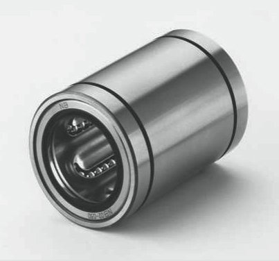
I plan to use these kind of bearings, instead of the current ones:
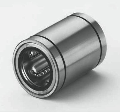
I think this cannot be used for the Z axis, since it has to stay opened at least on one side to attach the tool mount, but it would at least be used to link the X and Y axis together.

Do you have any thought, suggestions, warnings or recommendations before I try? Any advice would be appreciated, I’m pretty sure it will work but several brains are often better than a single one!

I’ll start to work on the 3D design this week.

Well, not much activity there XD

I was expecting to get at least a few suggestions
Anyway, I’ll inform you guys about how this will turn out.

I did a bit of 3D drawing and here is how it looks like for now.
I think I will try to print this version and see if it works.

If this turns out to be OK, I may redesign the whole thing to make it stiffer, first I need to know if this could work fine with those bearings.

A few pics:

Your bearing pic isn’t showing up…at least all I see is a box with an X in it…

I read where you had to use the heat shrink in a previous post. Mine is tight. Not crazy tight, but tight. I wonder if your prints are a tad oversized.

@Brian , heat shrink on what ?

He used heat shrink on his x/y tubes.

Sorry for the first pic, I cannot edit the first post anymore (this rule is really annoying actually… Even more annoying: after I edit a post it won’t even show up anymore… I then try to post it again but I get “Error: Duplicate reply detected” even though nothing shows up!!) :wink:

Here it is, I hope it’ll work this time (5th time I try, if it still doesn’t well, so be it):

Yes, I’ve used heat shrink on my X and Y tubes, since the bearings were not making contact (you can see what we are talking about if you go and check my build “My Cnc made in China”). I guess this doesn’t help at all with rigidity either. It was indeed probably because of a calibration issue on my 3d printer, but I don’t really know why since otherwise my prints usually come with accurate dimensions.
My guess is that I was printing on the very side of the printing area since I had huge holes in my glass plate and maybe the delta is less accurate there. This puzzles me.

Anyway, Those bearings seems to be really awesome and the ones I received already are super smooth. They were actually not much more expensive than the cost of three bearings, so I thought I could give them a try.

In case the pic above didn’t show up, you can check here, this is where I bought them:
https://item.taobao.com/item.htm?spm=a1z09.2.0.0.SyWpEh&id=520801851507&_u=n23vfsu660e

Only 6 yuans for the 60mm one, that’s less than one US dollar. I love taobao, best online sales platform ever :smiley:

They have a dust seal, so hopefuly the performance should remain the same no matter how dirty the Cnc gets (which was not the case with standard bearings, they tend to accumulate dust and make the ganty harder and harder to move). Well, that is if the dust seal proves to be good. My guess would e that the dust will eventually get inside, but I could always find solutions to avoid that later.

Also, since the plastic has its limits in terms of hardness, I found out that occasional re-tightening of the bearing was necessary, probably because the screws are deforming slightly their holes or for some other reason. Last, but not least issue, I had to compromize between play and smooth movement, the more I tightened the bearings the less play I had, but the harder it was to move everything. I should’nt have this issue anymore with those.

There will be four 60 mm long bearing (on for each motor slide) and two 120 mm long ones for the X and Y axis on the gantry. I would really like to find a similar solution for Z but I have to find opened linear bearing with a large enough opening and at the right size. I’m pretty sure they exist so I’ll look into that later, if it turns out to work fine on X nd Y.

Right now I’m printing the first motor slide, Hopefully I should have them all four ready by tomorrow!

Ok, I’ve got two motor carriage already ready and made a quick fitting test.

It run so much smoother than with the old bearings… So far it really seems to be great, no play at all.
I’m really looking forward to see how the central carriage will turn out, I’ll start printing it this afternoon.

Some pics of the motor carriage:

Well, I like your way of thinking. That’s bound to be smooth as silk.

Linear bearings wear grooves into hardened steel rods on Reprap printers relatively quickly. I imagine your tubes will be damaged soon. The Igus polymer bushings that have steel sleeves might be a better option. I could be wrong though.

Interesting information, I didn’t know that.

The tubes I use are actually supposed to be used especially for these kind of bearings, I wasn’t able to make a scratch on them with any file or any titanium or HSS drill bit, they are incredibly tough.

I’ll keep an eye on this and report here if they turn out to wear the bars at some point. Thanks!

Here is the link of the shop where I bought my bars, maybe a specialist of materials characteristics could tell us more?
https://item.taobao.com/item.htm?spm=a1z09.2.0.0.ko6GrG&id=44835956345&_u=o23vfsu044e

I’m still in the process of finishing mine MPCNC, but as for the strength of the middle part, I would say that the weakest point is in the XYZ part, not XY (look to the picture). Maybe it is good to somehow redesign them?

You’re absolutely right.
I plan to redesign this too, once I validate the concept for the other axis.

My plan would be to use the same kind of ball bearings, but opened on one side. I just need to find appropriate ones.
Some other solutions are possible, I’m currently not entirely decided which one I’ll use.

Any suggestion is welcome though, it is possible that the ones I imagine may not be the best :slight_smile:

Since the bearings are not sealed, you may want to add some sort of sweep to clean the rail. I plan to do this as a mod for my MPCNC to keep the rails clean. Much like on a sliding compound mitre saw.

Actually, the bearings are sealed. But I don’t trust the seal to be super efficient either. I think I will simply cut rings from sponges and print an enclosure that I’ll fix before the bearings. No big deal :slight_smile:

Well, I just made the first test of one full axis (Motor slide-Central carriage-motor slide) and the difference is incredible so far. It much soooooo much smoother, I can move the whole gantry with my little finger (keep in mind that I was using heat shrink tubes on the middle tubes, so my CNC was probably harder to move than yours).

But smoothness is not the best feature, I think the greatest thing of all is the total absence of noticeable play from one side to another: if I move the axis manually from one of the motors, the carriage on the other side follows immediately. I used to have quite a bit of lag before when I was doing this. It should mean that I won’t have to check the squareness anymore before doing a job, I should be able to move the gantry by hand, hit “start job” and grab a beer.

Still need to print the last gantry part and make some tests, but so far it looks like I’m on a good path!
Keep you guys posted :slight_smile:

The usual bearings have an inner and an outer race as well as dust shield protecting the ball bearings. Linear bearings have the ball bearings exposed to the rail, through a seal mind you, but still exposed. That’s what I was trying to say. If the rail has a nick or is dirty, it’ll cause the little ball bearing to get gung up on it.

Yes, you’re absolutely right.
But actually, a similar phenomenon appears with the standard bearings: dust accumulates on the outside ring, preventing them to run smoothly.

I’m not worriying about any dent on my tubes, I don’t have any diamond hammer to throw at them, so they should not get damaged before a long, long time :smiley:

If dust turns out to be a real issue I’ll think of something. Hopefully it should not be too horrible since I have dust collection now.

I would really like to get @vicious1 opinion on these mods, since he’s the one who knows everything about this marvelous machine. Hope he sees this :slight_smile:

I’m not sure what to say. You have modified a lot of things because you said your printer calibration was off. That might be the root cause of all these issues you are trying to fix. Heat shrink on the rails is not a good idea, the bearings you want to use generally are not going to last very long and offer no adjustability and require very finely polished tubes. Looks like your center geometry will collide with those bearings. I have no issues with you trying anything. But I can’t really help either I have none of those parts and am very happy with how mine works. I am really starting to get some nice results now even with 3D printing.

I would say adjust your printer and print all the parts correctly and try again, my way. You have a lot of things on there that will affect the machine, larger than recommended spindle, a dust shoe with a long tube, and that heat shrink are the most serious offenders. There is a balance.

Properly printed parts and a spindle the right size that is closer to your gantry will dramatically increase your rigidity, as well as removing that giant vacuum tube. My philosophy on the center is have as little touching it as possible.