One of the things I want to change about my LR3 is the Y rail. Because the gantry rides along the 1/2 EMT Y rail without capturing it, I have had several instances where the gantry lifted from the rail during a plunge. Obviously I can avoid this by using multiple smaller steps down or using a shallow ramp or even just reduce the plunge feed rate. But I prefer to push my machine. I looked at existing SBR rails but did not find any 10 foot lengths. I am not sure that I would be willing to pay for such an expensive item.
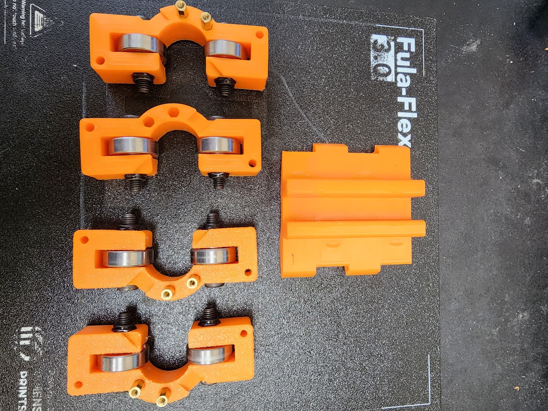
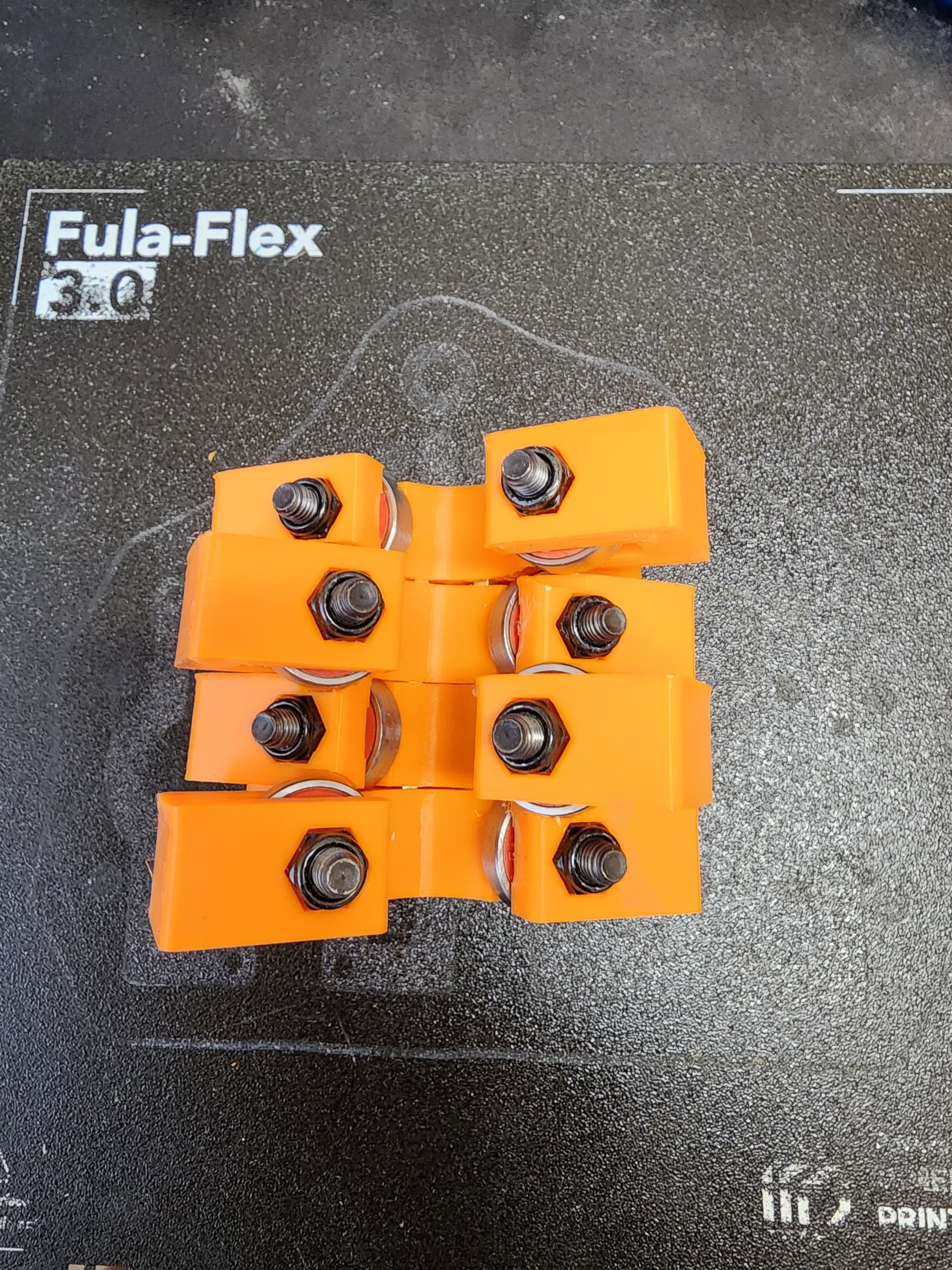
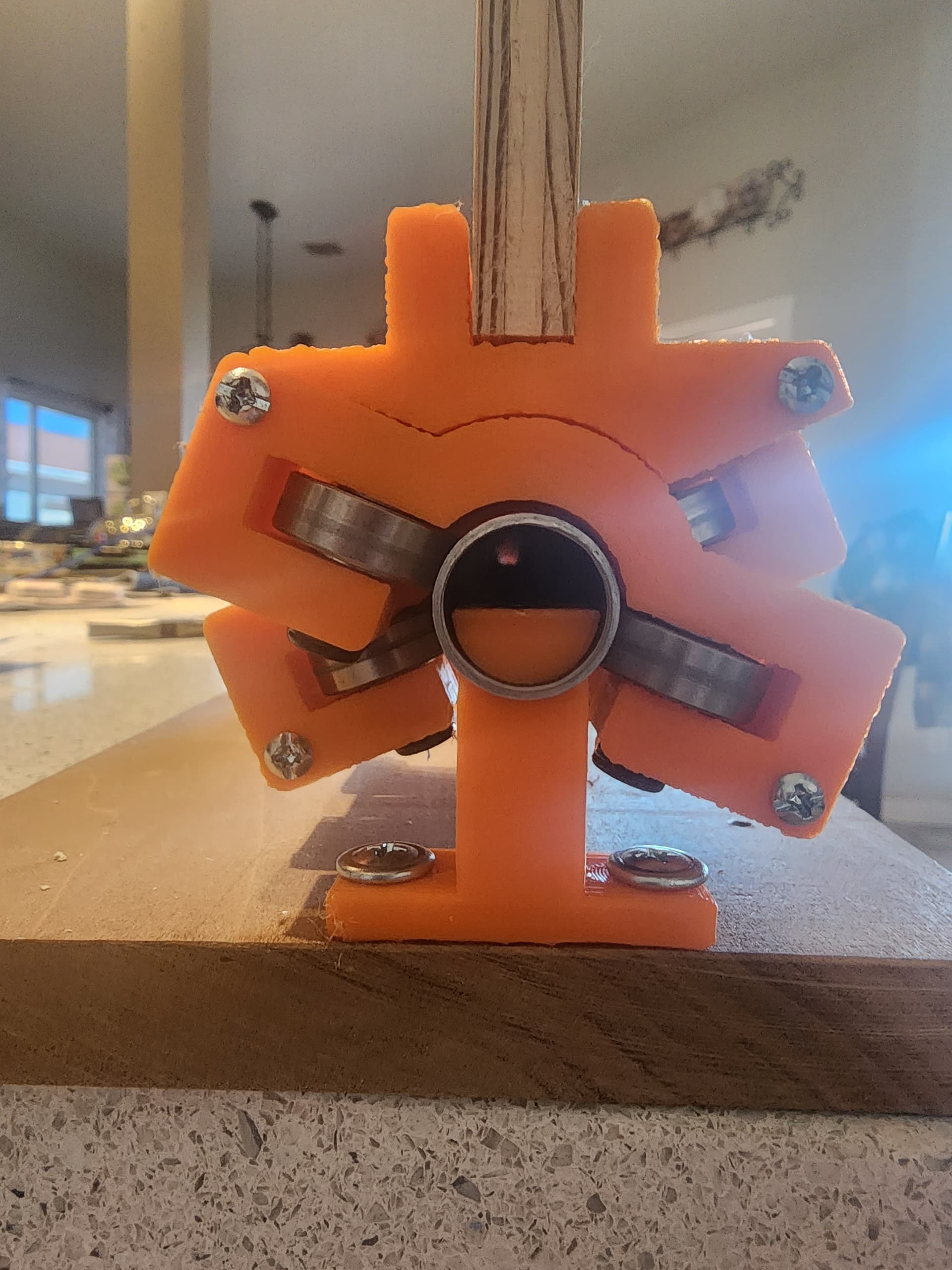
So I decided to design my own SBR-like block that captures 1/2 EMT. After a few iterations I have a design I can work with.
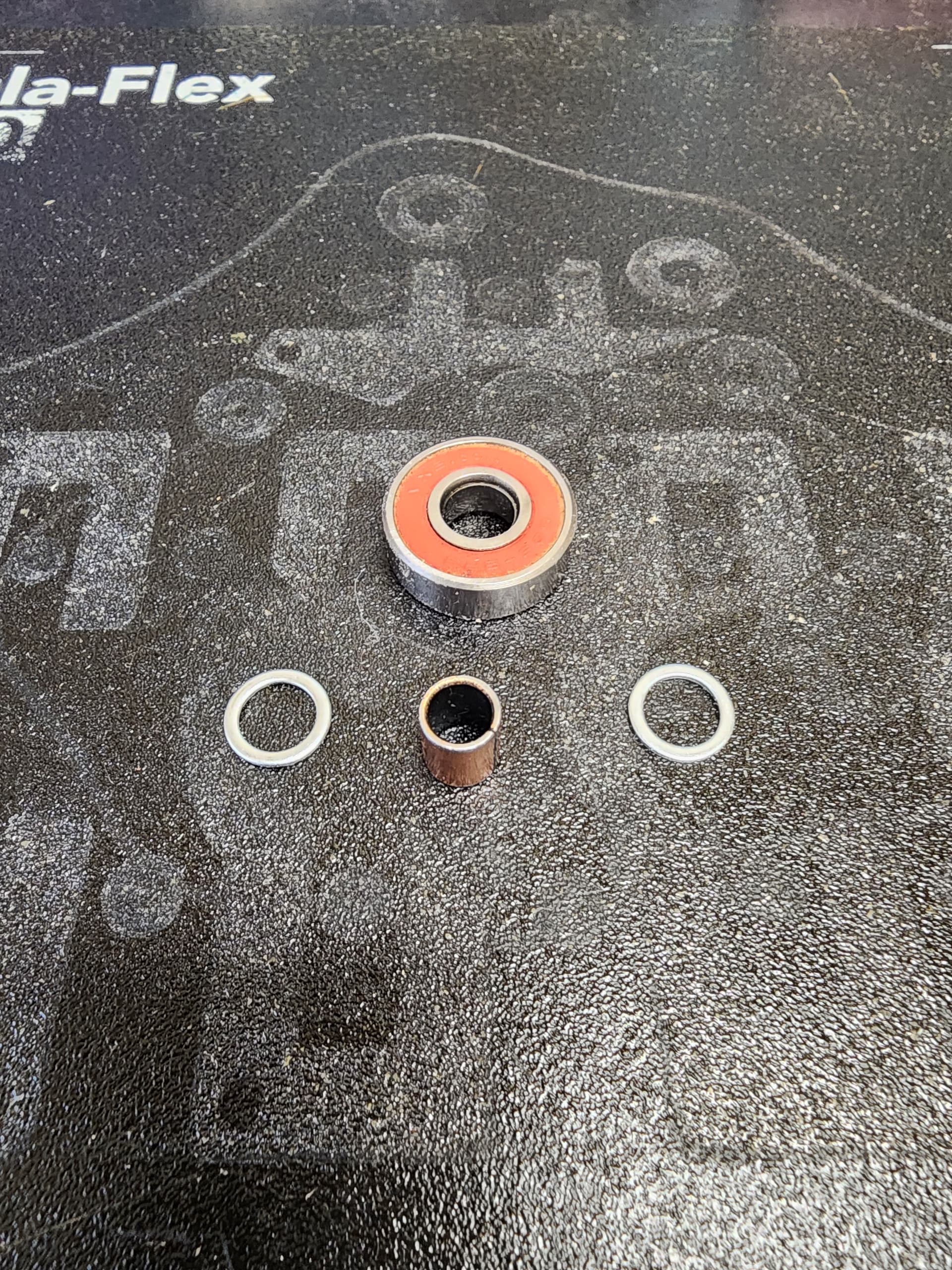
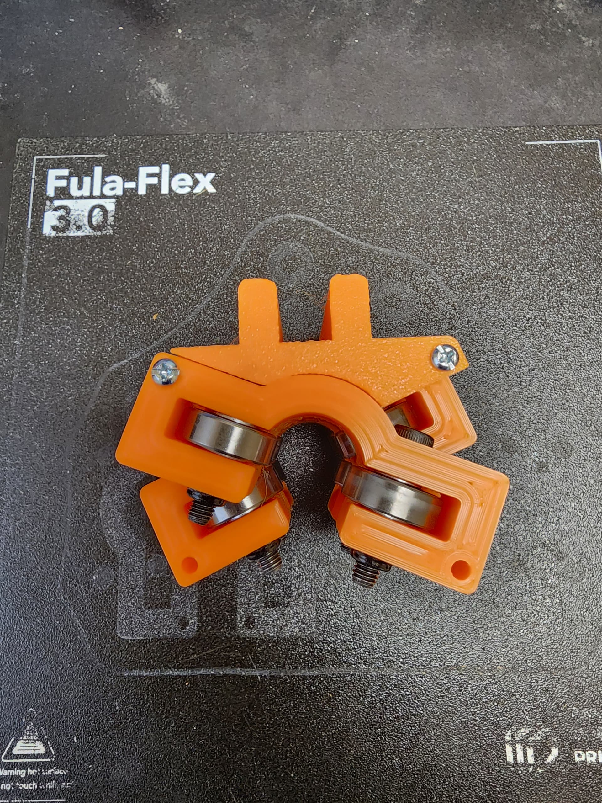
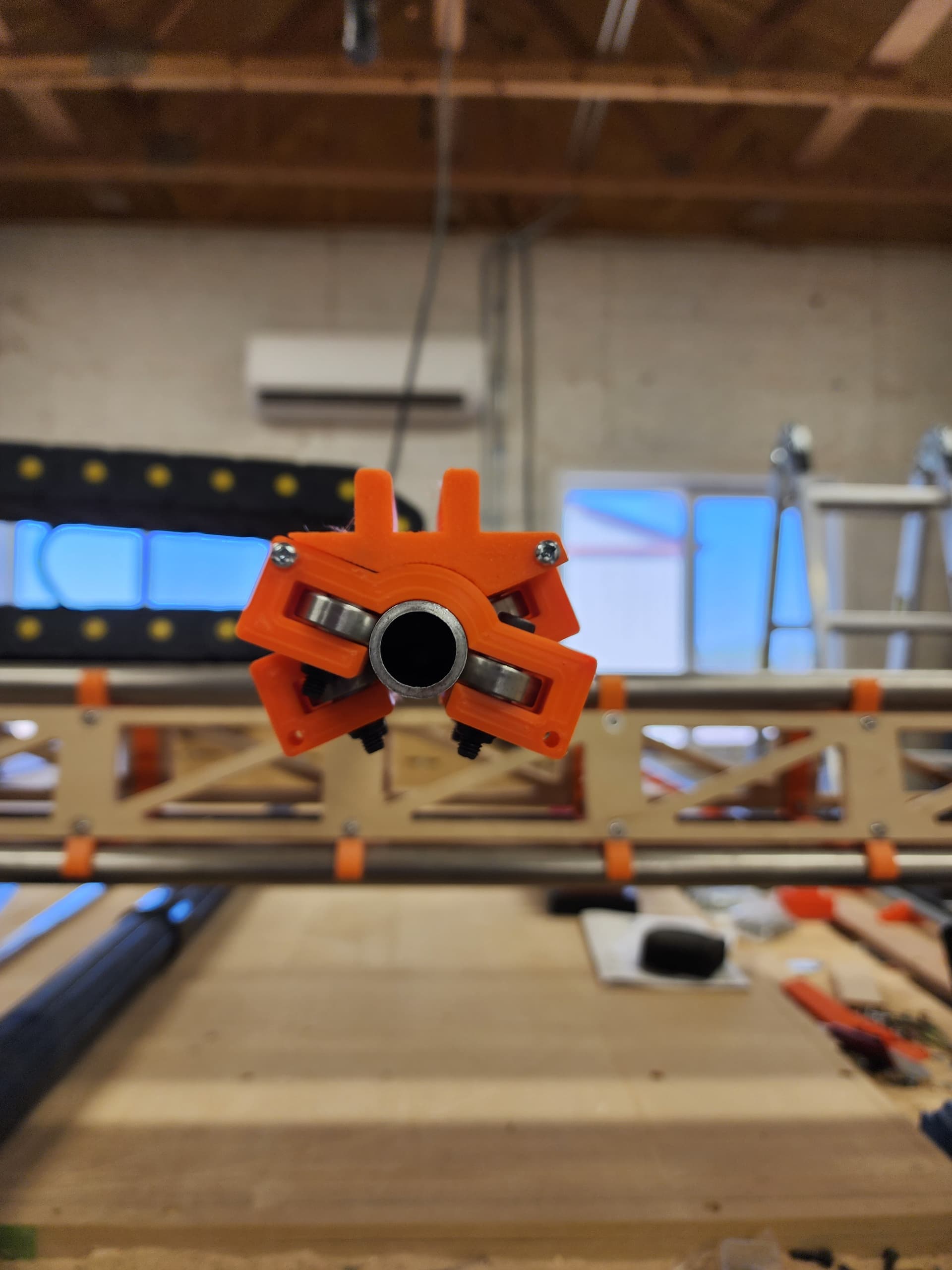
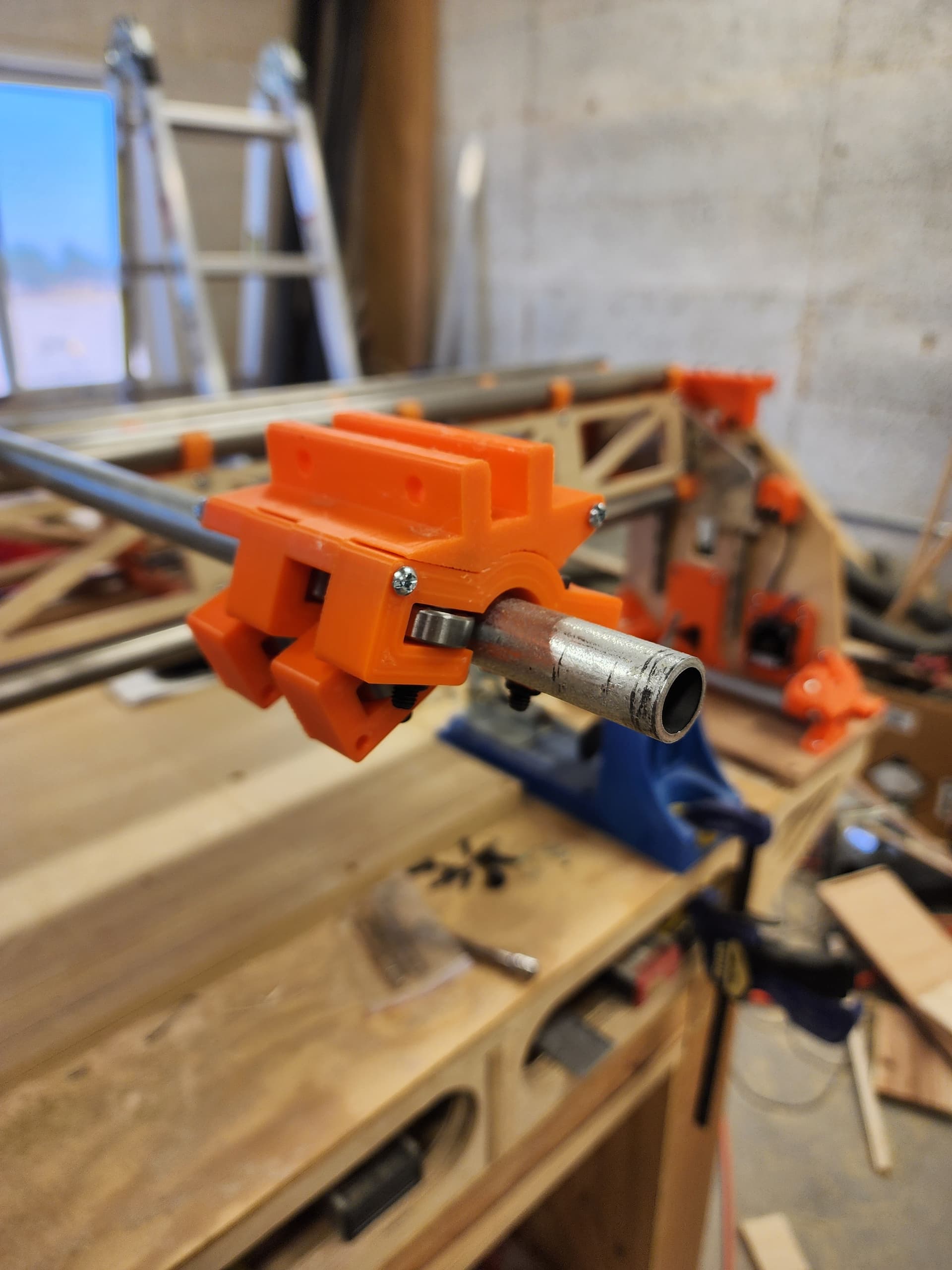
It uses 4 dual bearing housings that are each offset from the one(s) next to it. There is also a gantry mount that attaches to the block. The one in the picture is just an example and doesn’t work with the LR3. That will be easy enough to design after my work on the rail.
My design avoids using the 5/16 (8mm) bolts because I found they caused my design to be too bulky. So I opted for M8 x M6 reducing bushings and racing washers instead.
LOL, says the guy with a 4 pipe gantry on his “LR3”, complete with meshed belts, tensioners to limit slack/slop along Y axis and a bunch of other mods. Looking forward to seeing what you come up with
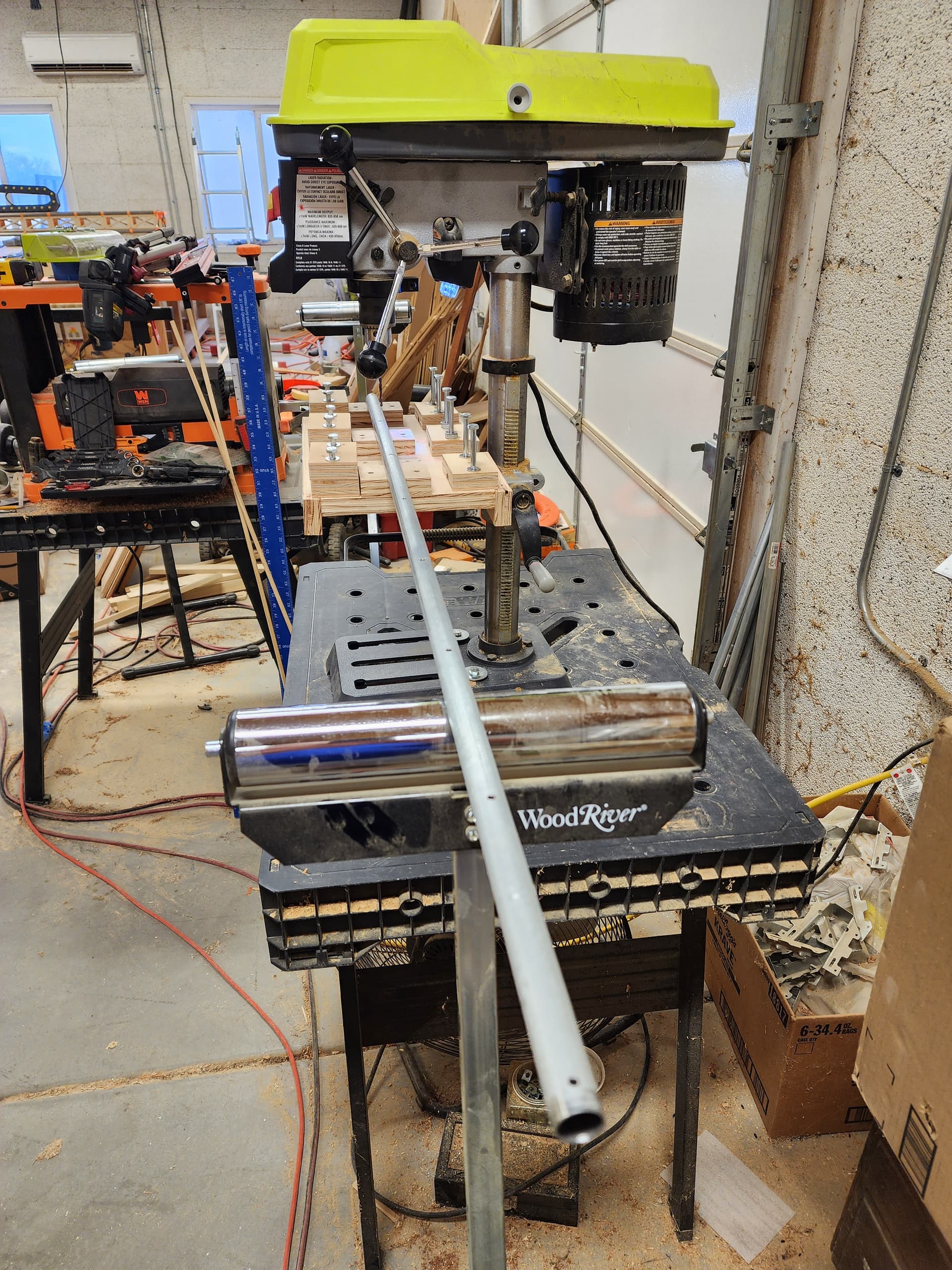
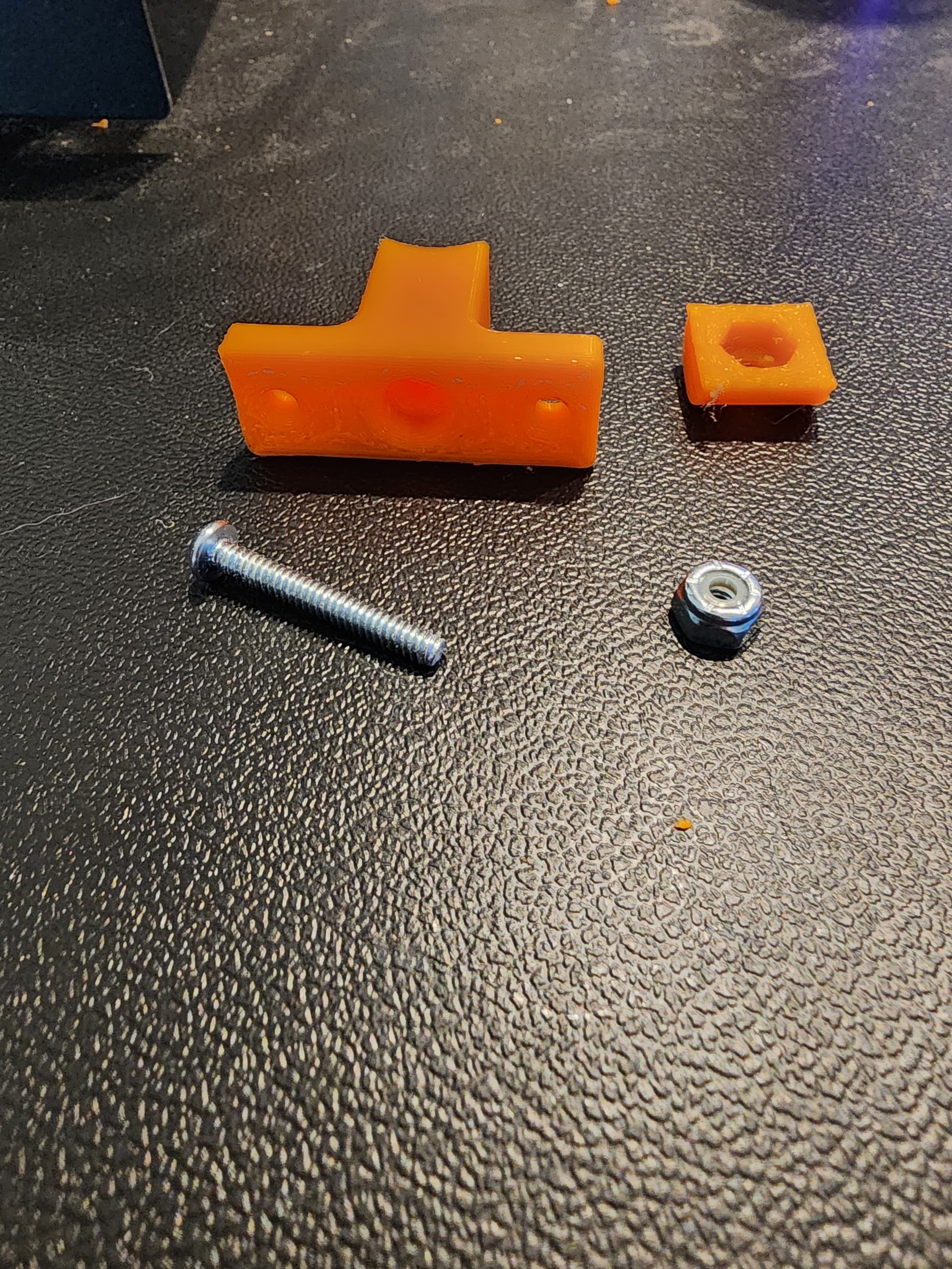
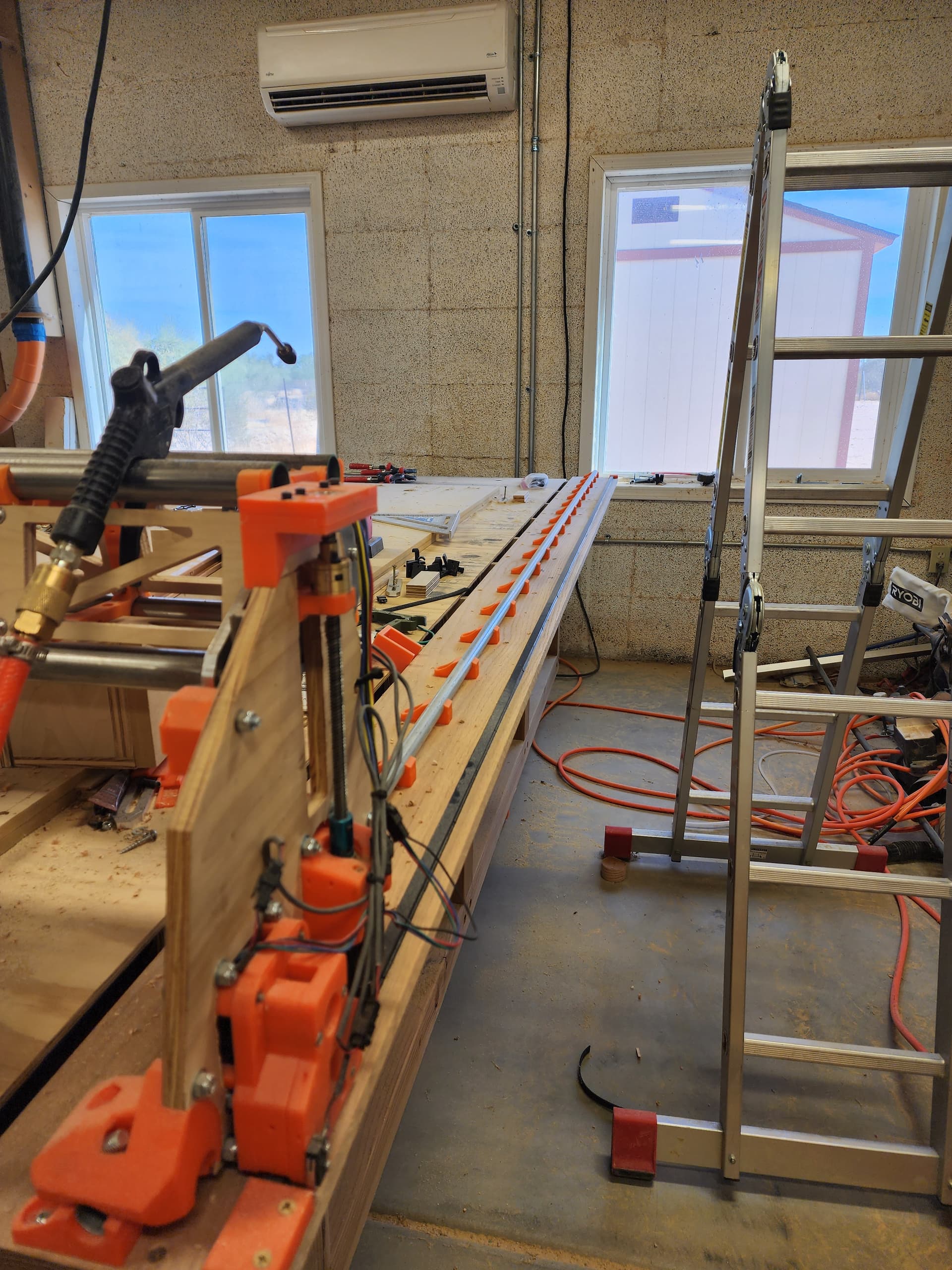
I am finally back on my rail project. I needed to elevate the rail to allow the new rail mounts to glide along the Y-axis. For this I designed both a standoff for the rail to rest on and an internal clamp to hold the rail in place. Although my current rails are supported at 200mm intervals, I decided to go with 150mm spacing because the rail is elevated.
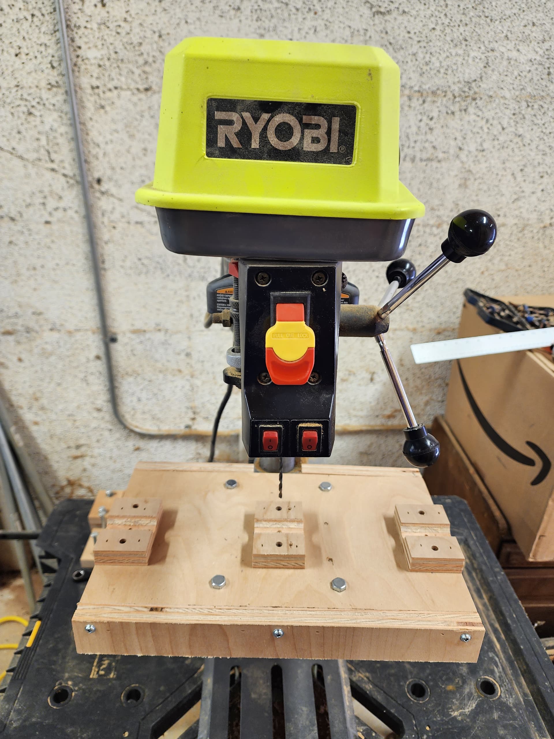
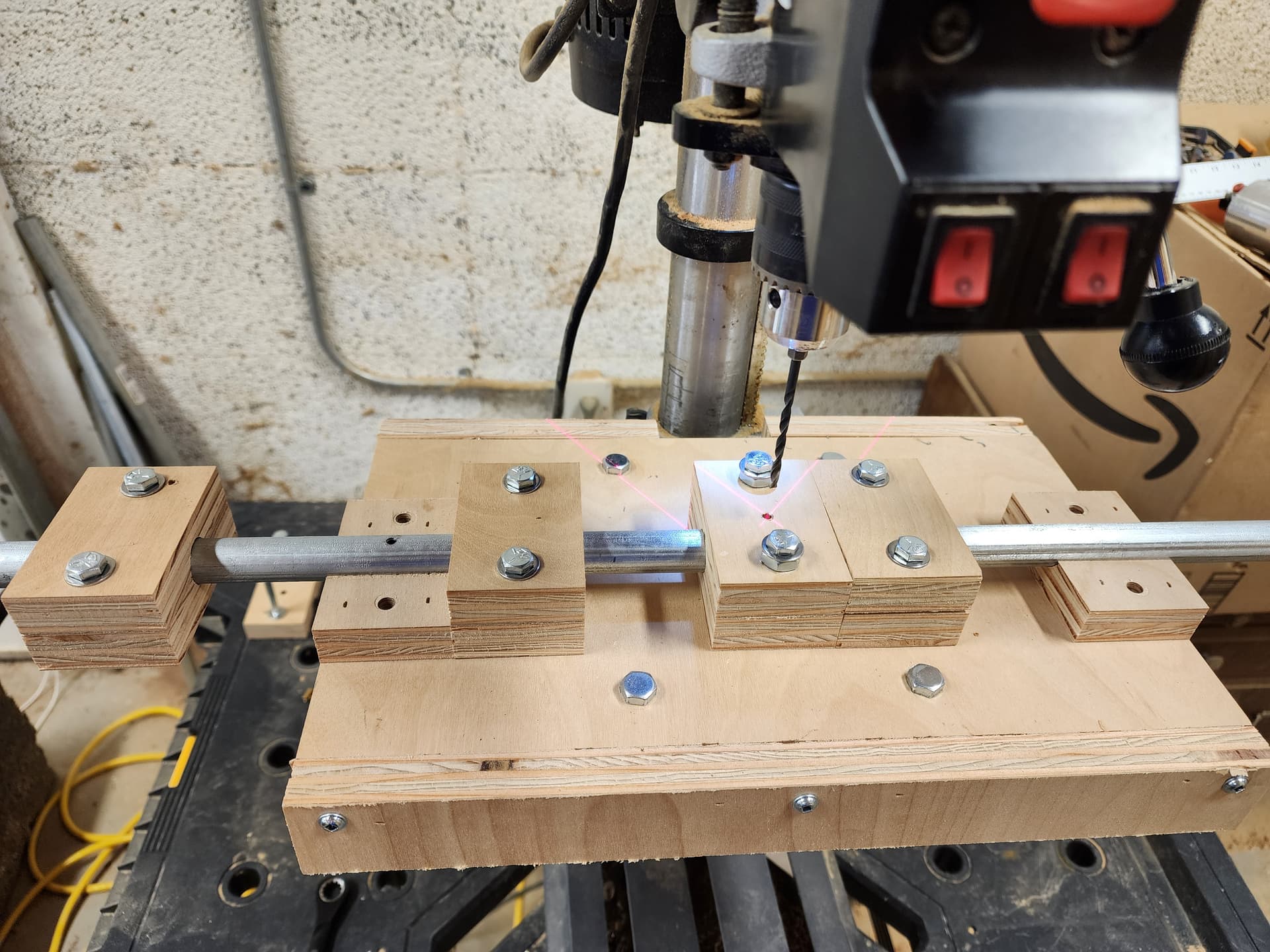
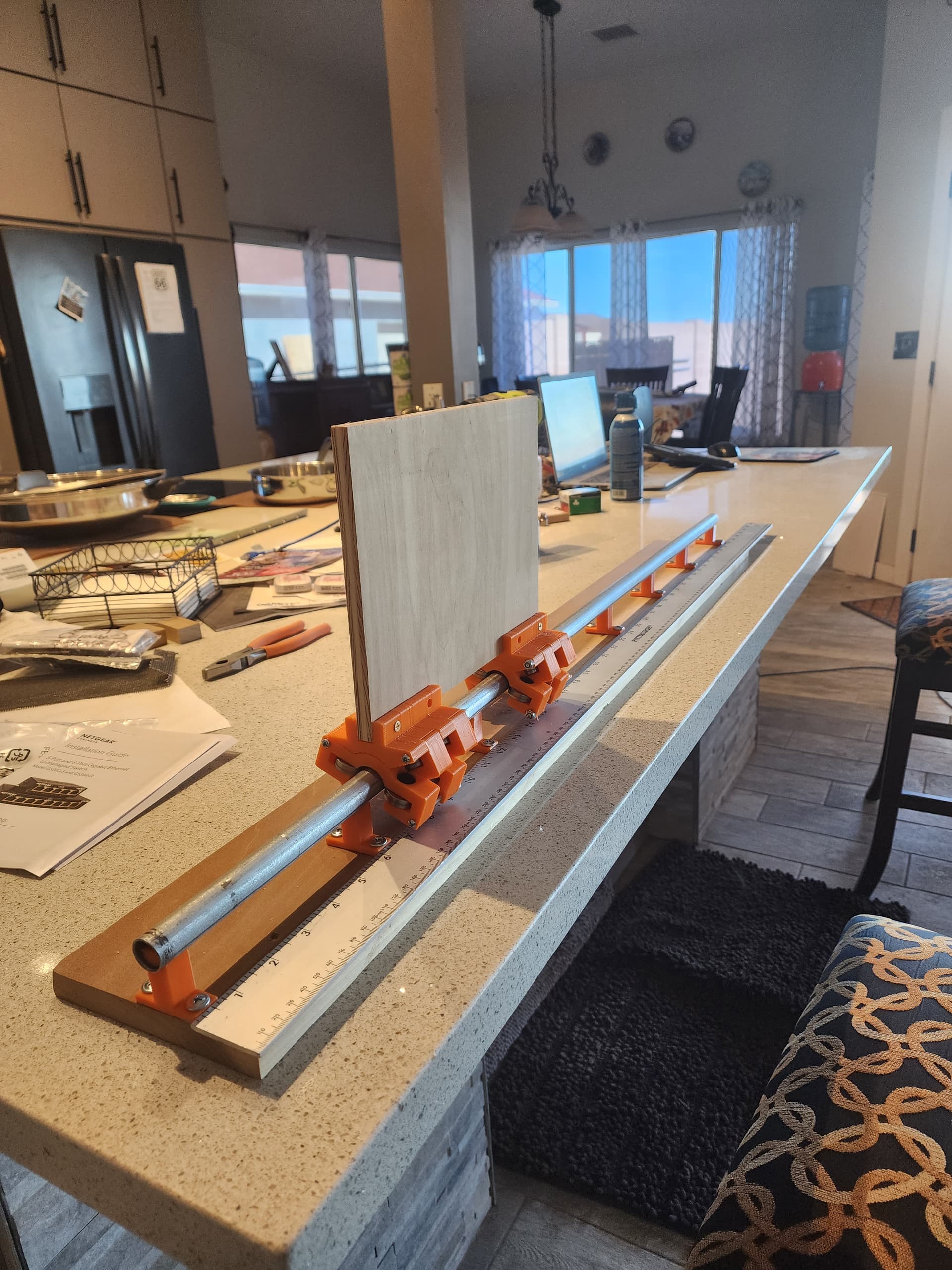
But for this to work I needed holes drilled at 150mm intervals along the rail. While I could have created a fixture on my current full sheet Lowrider to drill 1/2 way (or more) along a blank rail and then flipped (or indexed) the rail to complete the operation, I wanted to see how I would do this if I only had my much smaller Lowrider. Again, I could have created a fixture on my smaller Lowrider and then drilled and indexed multiple times to complete the operation. But I decided to have a little fun (and make my life harder) and create a fixture for my drill press to manually drill each hole. Maybe I am sadistic.
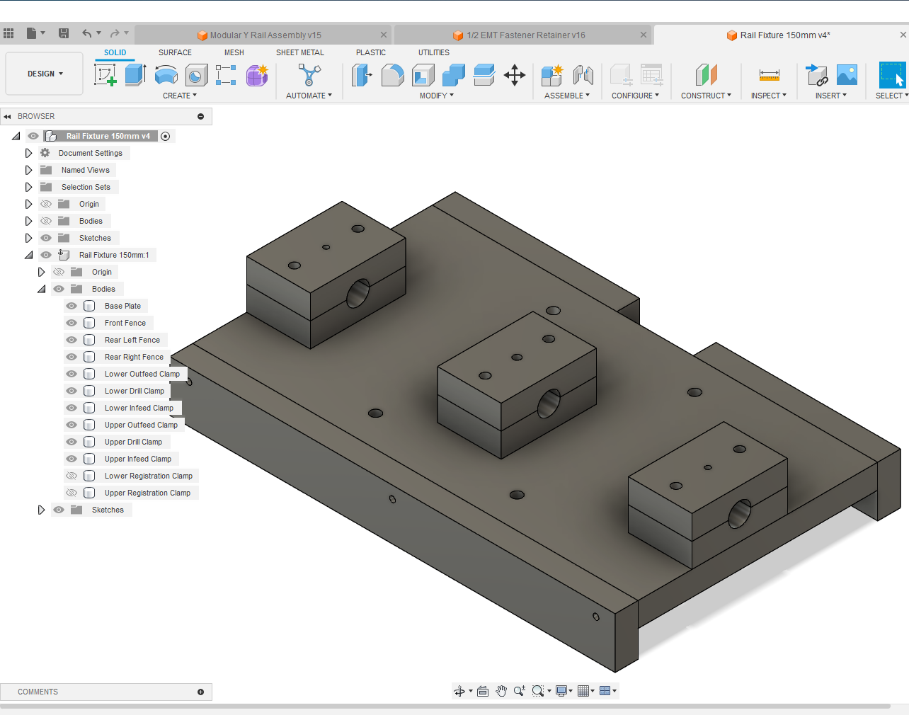
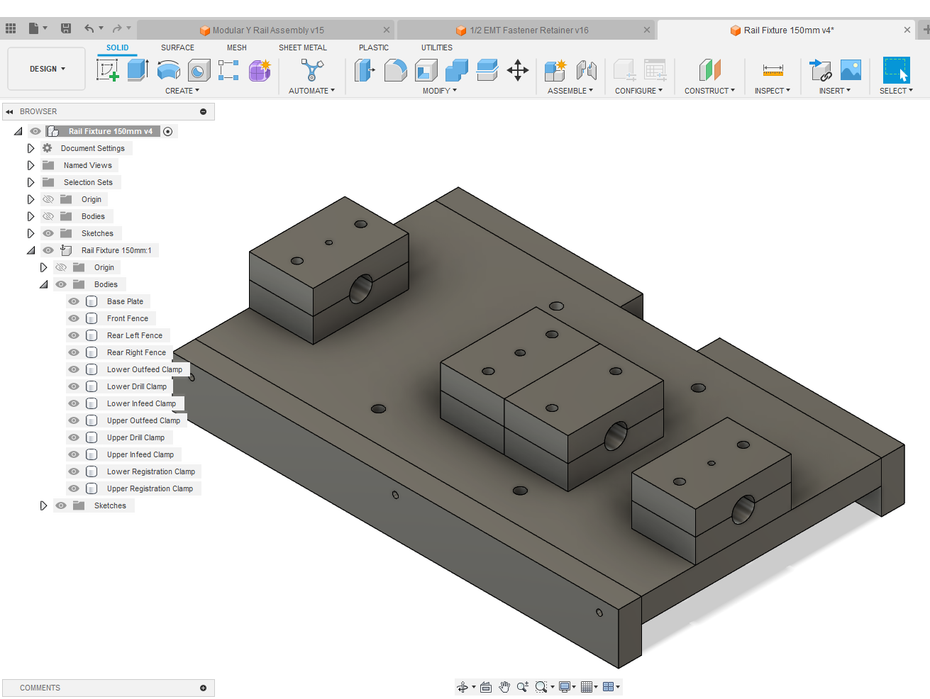
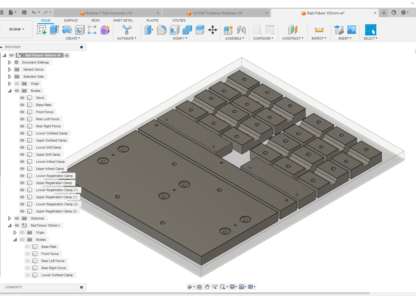
After completing the design of my fixture, I placed each piece (virtually) into a piece of stock (3/4 plywood offcut) and created the toolpaths needed.
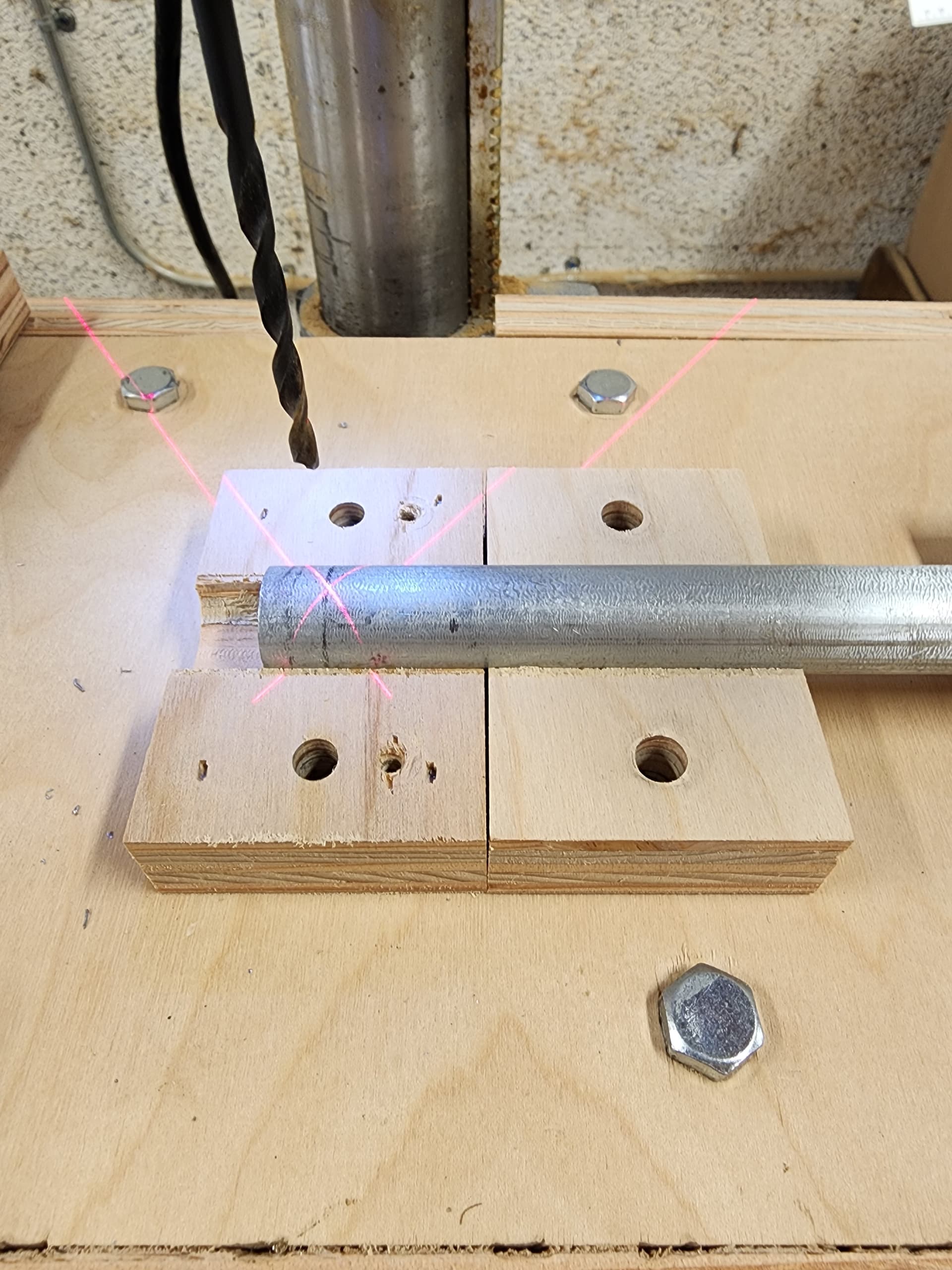
Now I was ready to begin drilling the holes in a 10’ stick of 1/2" EMT. This is equivalent to 3048mm which would be 21 holes on 150mm centers with 12mm on each end. After marking the initial 12mm position I place this mark at the hole in the Lower Drill Clamp with a Lower Registration Clamp. The Registration Clamp assembly is needed for not only indexing the rail 150mm but also for maintaining the correct rotational position of the rail.
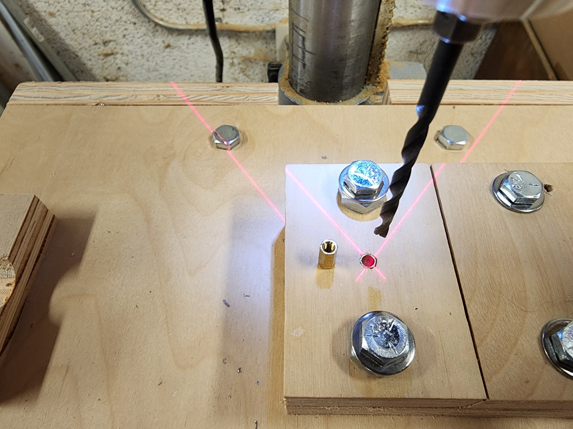
With both upper clamps in place I was ready to drill the first hole. By the way I had inserted a brass hex space in the Upper Drill Clamp and bored out the threads to help keep the drill bit aligned and consistent as I processed the rail.
Next I removed the Upper Drill Clamp but NOT the Upper Registration Clamp and then moved (indexed) the rail so that the Registration Clamp assembly was against the Lower Outfeed Clamp. I also added a Lower Registration Clamp against the Lower Drill Clamp and then added clamps for both. Time to drill the next hole. Then it was a simple matter of rinse and repeat.
As the Registration Clamp assemblies were indexed off the the fixture they were removed and reused as needed. I had created three of these assemblies for this process.
That’s an interesting idea to use a rack with the belt. Will the belt a short belt loop around like a tank tread or will you use a belt the full length of the rack? Is the goal to mitigate the effects of belt stretching?
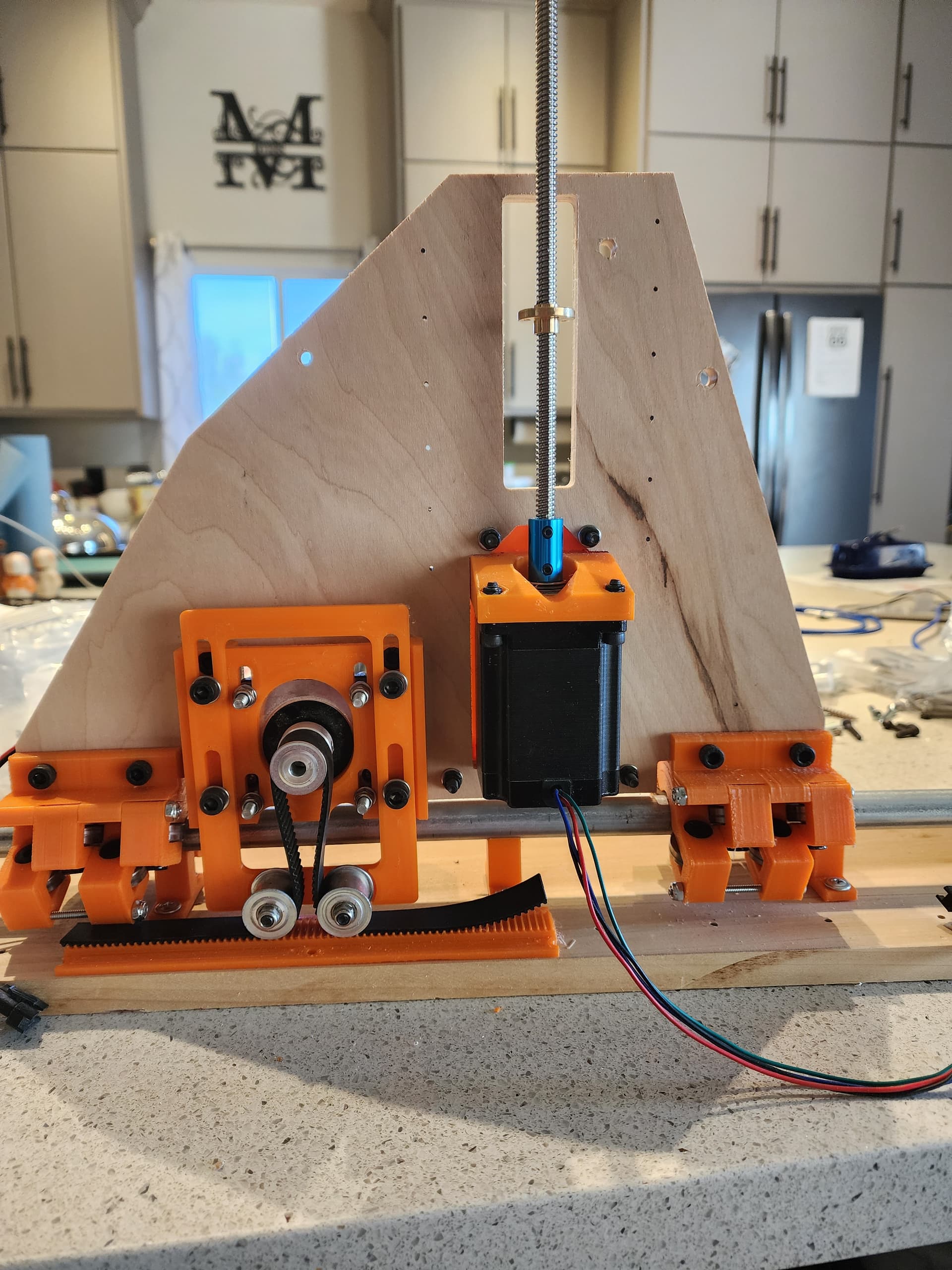
In my first kinematics update to my Lowrider 3, I rearranged the NEMA17 motor for the Y-axis for a rack and belt design. This was done to mitigate the belt stretching.
Then I replaced my Makita router with a 2.2kW spindle but I was not happy with the sagging when the spindle was at the center of the gantry. So redesigned the gantry from 2 rails to 4 rails to more easily carry the extra weight.
I was missing the power I had become accustomed to with my previous Lowrider 2 that I had upgraded to NEMA 23 motors. My next update was to rearrange the X-axis motor mount and replace the NEMA 17 with a NEMA 23. This has been working great for several months now.
I am almost ready to finish my migration to NEMA 23 motors. Just a little more PLA and an offcut from one of my cabinet projects…
Yeah, lots of neat mods. Thanks for sharing your thinking and progress.
If 3D printing rack anyway… Given your Y rails are captured, already considered 3D printed helical rack and pinion, so no Y belt? With Nema-23 and rigidly captured Y rail, at some point will you possibly end up with $$ metal helical rack and pinion?