Thanks for that info. After reading this, I did recall seeing that in a thread somewhere. Maybe it will stick to my brain this time.
I burned a grid 450mmx250mm with 25mm spacing on the plywood base for my engraver yesterday. My current maximum dimensions are 495mmx255mm. This was a good way to check the squareness. Putting a framing square on it, I can not see any problems. I measured the diagonals & they are 1-1.5mm different. Over a diagonal distance of about 515mm, that is close enough for me.

4 Likes
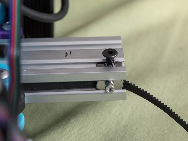
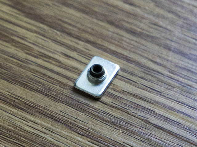
I changed the M5 T-Nut belt clamp to use a M3 T-nut which gives me another 2mm on each side. I actually had 499mm of travel on that axis, so this gets me over the 500mm mark.
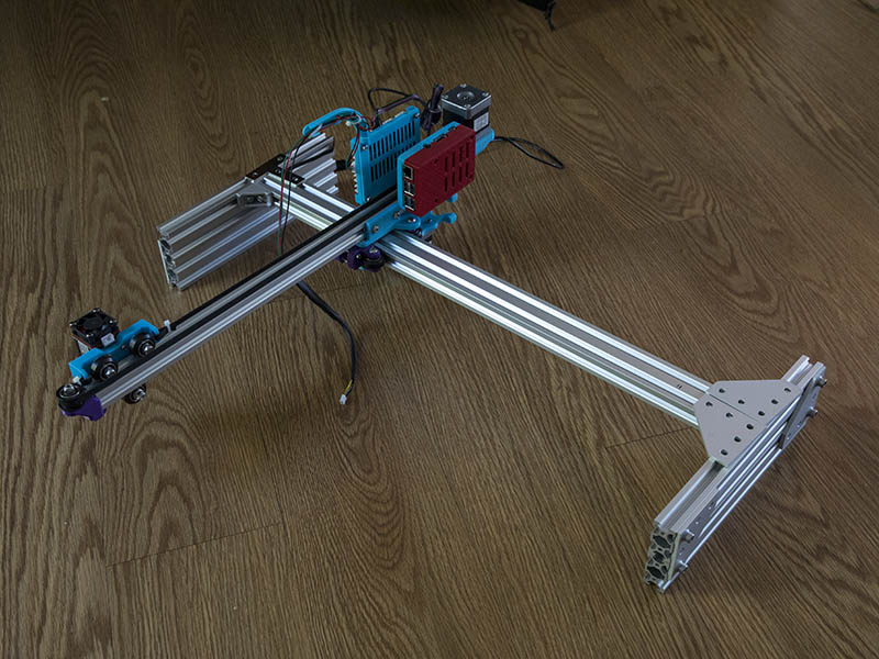
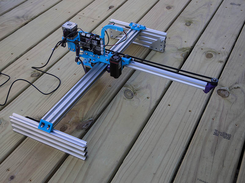
While I am waiting on the 2080’s to arrive next week, thought I would test the legs with some spare V-Slot I have. I don’t have any 2080’s, so I put 2 2040x250mm lengths together on each end. Cantilever is stiffer & this also gives a little weight to the legs so they should not have to be secured to a work surface. I used the plates that I had to worked the best.
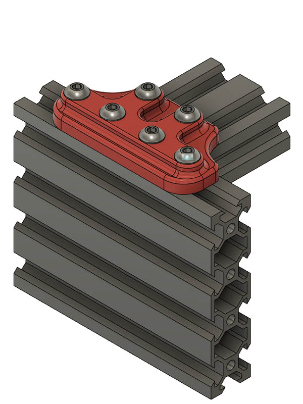
I am not real happy with those plate, so am printing a 3D printed plate to see if that will work ok. I could always cut one out of aluminum on my sphinx CNC, but this plastic part might be sufficient for the task.
1 Like
It’s starting to look like some sci-fi rail cannon!
If you look at Mike’s blog, the 7th message in his thread shows it looking similar to the Bird of Prey Romulan Ship from Star Trek.
As a note on M3 T-Nut idea, I think a better idea would be to use a short M5 set screw. The wheel on the carriage 1st hits the M5 head, so eliminating that and making it as short as possible seems the simplest solution to giving just a little more width.
Thought I had some M5 set screws but did not, so I went to local Ace store this morning & bought a couple of M5x5mm set screws & they do work perfectly & give me a little more width. I am now at 511mm (20.44") width along the 600mm 2040 axis. I started out at 495mm before making all these changes.
While testing the 2080 (2x 2040s) legs I realized the laser would hit one side before the wheels hit. I did not like that, so I changed to 2060. I thought about using 2060 before, but thought I would loose a little width. After looking at it again I realized I could make that work. Guess I should have waited a few more days before ordering those 2080 Misumi. I will just order another 250mm 2060 from openbuilds at some point or just leave it like it is. I do have 3 - 2060x1000mm lengths I was going to use for a delta printer a while back, maybe I will just cut one of those in half and be done with it. In the photo below you can see 2080 height on far side & 2060 on near side.
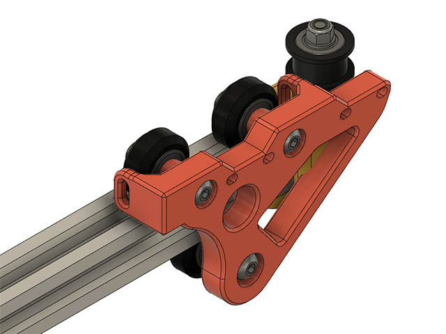
I want to get closer to the end of the cantilever with the laser so I can get closer to the edge of the deck at the house to engrave something. Right now I am at about 2.625" from end of cantilever to center of laser beam. I decided to redesign that carriage & add another set of mounting holes. Since that laser is not much weight seems like it should be ok. This gets me 2" closer to the end. I also have to redesign the end idler mount as that will hit it. I left the original 2 mounting laser holes in case I want to move it back to there.
1 Like
I am looking at putting some sort of laser shield around my laser & came across this design.
https://openbuilds.com/projectresources/laser-shield-box-for-spindle-adapter.285/
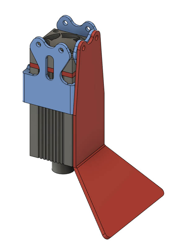
I am working on making a plastic part for this & see how it works before cutting some acrylic. I ordered some of that 3/16" acrylic shielding material from https://jtechphotonics.com/?product=445nm-laser-shielding . Can this stuff be cut with a diode laser or do I need to use my CNC router? I may just put a 12"x12" temporary wall of this in front of it while burning. I am being a lot more careful since I accidently forgot to have my glasses on when I went to check on it & glanced at it from 20 feet away for a couple of seconds before realizing I did not have my glasses on. No lasting affects from it, but don’t want to accidentally do that again. I am thinking just the 3d printed plastic shield might be all I need. Think I have it sized to be about 1" or so off the base. Any thoughts on that? I will probably put the acrylic shielding in place also. Here is the design I am working on. It is 2 parts. The blue part attaches where the laser mount is & the other part can go on any of the other 3 sides. Probably be difficult to focus if I put shielding on 3 sides.
1 Like
While I can provide no data on that exact material, I bought a piece of Lexan from HD just to see what would happen. Wasn’t pretty.
Just ended up getting all melty and then I had little black soot floaties all over my lair. Don’t remember what settings I was using, but haven’t tried since.
1 Like
After piddling with making changes to the carriage, end idler & adding laser light guard it is not working correctly. Initially it was not even firing the laser to start with. I tried my spare laser on this with same problem, so am thinking it is the controller board. I have not noticed any static discharge problem, but did still have motor wires connected to controller board while changing the parts & noticed the green light on controller board light up a couple of times when the motors moved. I should have disconnected them also as they do generate a little power sometimes when moving. I was going to hook up my keyestudio board, but need to make a better cable before testing that as the jumper wires at laser are to tight a fit. Here is a short video of what happens when I first connect the usb of the controller to my laptop. Almost sounds like a debug beep code for the controller. Anyone have a suggestion for this?

Replace or possibly just re-flash the Nano and swap out the drivers one at a time? At least they are all plugins! Quite efficient generators…nema17’s!!
After reflashing the firmware, then changing the Nano, then swapping the drivers it still did not work. Before soldering a special cable, I alligator clipped the wires together for the cable to the keyestudio board & it worked. At least it is not the laser. Looking at that EleksMaker Mana 3 board, I don’t see any visual signs of a problem. It is interesting that the motor circuits work, but the laser PWM does not. The fan on the laser runs, so I know it is getting 12v. My parts from China are finally starting to show up after 2 months, so maybe I will have 5 spare Mike grbl boards here soon.
Following the trace from PWM laser connection back to the nano, looks like it only goes thru a 101 surface mount resistor before going to pin D11 on the nano. Putting my ohm meter on that resistor, it reads 99.9ohm, so looks like that is ok. I get 0.3ohm from the PWM plug to the resistor & 0.6ohm from resistor to D11 pin. I am no expert at tracing pins, but does not seem like there is any problem in that PWM circuitry unless there is something else involved here. This Eleksmaker board also has a On/Off switch under the Nano which looks like it is tied to the 5v pin on the nano. Mine is set to Off & I did not change that & it worked on that setting before. Maybe I should try turning the switch to On? I am guessing that switch is similar to the 5v jumper on the skr boards where it gets the 5v from USB or from when the 12v is plugged in.
I found this interesting easy way to flash grbl using the openbuilds control program. The only problem is they are flashing with grbl 1.1g and not the latest 1.1h. I asked them about it & it is on his list of things to do.
How do I flash GRBL? Super Easy Way! - YouTube
That’s pretty cool. I wonder if the GRBL code is in the installation folder of the OpenBuilds application. I’m definitely going to check this out.
EDIT: My guess is it’s the snapshot_blob.bin file located in the program directory. I’m at work right now so I can’t test it.
When I inquired about updating to the 1.1h grbl, he replied with this link.
GitHub - OpenBuilds/control-grbl-buildall: Script to Build all the Grbl Variants for OpenBuilds CONTROL (Customised for OB machines)
If using GRBL AND laser mode is on s31=1 the laser.will not fire unless it is moving to test set s31 to zero
That was a good thought, but I have $31= 0 & $32 = 1. I also did not change any of these settings between the time it worked & did not work. These are also the same settings I put into the keyestudio controller that worked. Here are my current grbl settings for reference in case I need to change any of the others.
$0=10 ;Step pulse time, microseconds
$1=25 ;Step idle delay, milliseconds
$2=0 ;Step pulse invert, mask
$3=0 ;Step direction invert, mask
$4=0 ;Invert step enable pin, boolean
$5=0 ;Invert limit pins, boolean
$6=0 ;Invert probe pin, boolean
$10=1 ;Status report options, mask
$11=0.010 ;Junction deviation, millimeters
$12=0.002 ;Arc tolerance, millimeters
$13=0 ;Report in inches, boolean
$20=0 ;Soft limits enable, boolean
$21=0 ;Hard limits enable, boolean
$22=0 ;Homing cycle enable, boolean
$23=0 ;Homing direction invert, mask
$24=25.000 ;Homing locate feed rate, mm/min
$25=500.000 ;Homing search seek rate, mm/min
$26=250 ;Homing switch debounce delay, milliseconds
$27=1.000 ;Homing switch pull-off distance, millimeters
$30=1000 ;Maximum spindle speed, RPM
$31=0 ;Minimum spindle speed, RPM
$32=1 ;Laser-mode enable, boolean
$100=160.000 ;X-axis steps per millimeter
$101=160.000 ;Y-axis steps per millimeter
$102=250.000 ;Z-axis steps per millimeter
$110=6000.000 ;X-axis maximum rate, mm/min
$111=6000.000 ;Y-axis maximum rate, mm/min
$112=500.000 ;Z-axis maximum rate, mm/min
$120=500.000 ;X-axis acceleration, mm/sec^2
$121=500.000 ;Y-axis acceleration, mm/sec^2
$122=500.000 ;Z-axis acceleration, mm/sec^2
$130=495.000 ;X-axis maximum travel, millimeters
$131=255.000 ;Y-axis maximum travel, millimeters
$132=0.000 ;Z-axis maximum travel, millimeters
Sorry it is s32 that is laser mode memory getting bad not s 31 did you try that again sorry
Actually the laser will will work with $32 = 0, it just does not turn it off between G0 moves. I initially had it set to 0 and was wondering why it was not turning it off between moves until I found the following thread on the lightburn site. Laser doesn’t turn off between cuts - LightBurn Software - LightBurn Software Forum
1 Like
Are you using M4 and make sure that you aren’t testing with G0 moves they turn the laser off😀
Nope, just use M4 S2 or M2 Sxxx like I did before it stopped working.