I don’t know. I just read about it somewhere (on this forum), so i thought I should share the information.
It is not a new way, for whatever reason the download all button is broken. The button simply linked to this URL for each thing on the site.
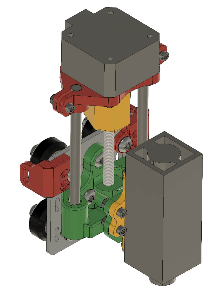
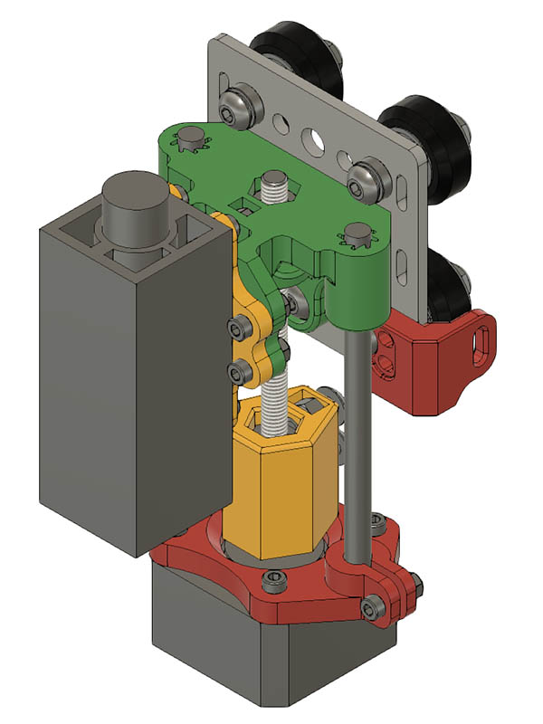
I have been wanting a Z-axis for the laser or rolling plotter for a while & started playing with a design the last couple of days. This uses an M6x70mm bolt for the Z-axis drive, M6x100mm smooth rod and a pancake nema 17 motor. I chose M6 instead of M8 to cut the weight down a little. It will probably be too heavy for the cantilever laser, but am thinking of adding another side to it if this works ok. The green bracket is bolted with 3 -M5 screws to the metal X-carriage. Rather than using metal bushings, I am going to try this design that is similar to the igus polymer bushings but designed into the bracket. My little sliding pen mount on the rolling plotter uses M3 rods from an old DVD drive & they move quite well without any bushings, so just having a nice sized M6 hole might work just as well for use with a laser or pen. I will do some test prints of different sections before printing all the parts. I will have to order the M6 bolt & M6 smooth rod. Here is my design so far. The only potential problem is the green bracket might need more support to keep the motor from wanting to lean over. There is 20mm of height that the smooth rods fit into on the green bracket. I am open to suggestions if you see something wrong with this design.
Maybe im just not seeing it right. It looks like the green bracket is bolted to the carriage, and the laser is bolted to the green bracket. Wouldnt this just make the stepper motor mount move up and down?
You are right. Not sure what I was thinking. Maybe I can blame that on this cold I have. Back to the drawing board. I did realize in the night that I had 2 nuts on the green bracket interfering with the 2020 V-Slot I did not model.
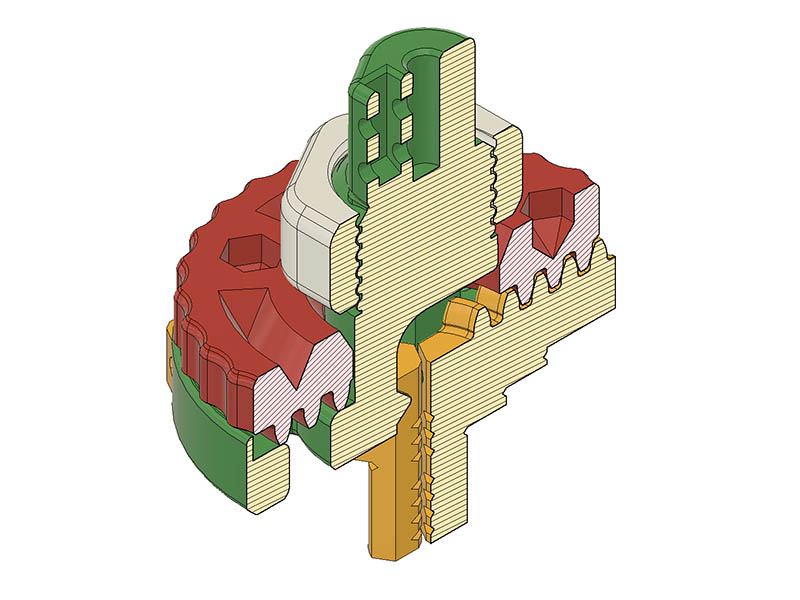
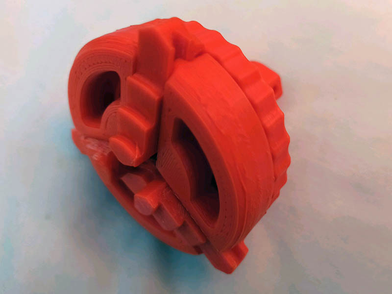
I decided to revisit this 3-jaw chuck design for a vertical pen mount. I couldn’t figure out the spiral path a couple of years ago, but after watching a YouTube video on it, it was quite easy. After reproducing this design Nano Chuck by PRIma by PRIma - Thingiverse with better tolerances for me, I realized something interesting. All the chuck designs I had seen used a rectangle profile along the spiral path. Why not use a gear tooth profile sweep along the spiral path. I was using a spiral with a 6mm pitch, so I wanted to match the gear tooth spacing to that. In fusion 360, I used the spur gear python script to create the gear. I used a 24-tooth gear with all the other defaults. I changed the module size until I got an arc length between teeth to be about 6mm. A module size of 1.91 came out to an arc length 6.0004 between teeth which was closer than I expected. 2020 hindsight, I should have used a backlash of 0.2mm instead of dropping the tooth down 0.2mm from the opposite tooth. I still have to tweak the design a little, but my first test of this works better than I expected. This is designed to fit on top of a Nema 17 motor & I added the threaded nut to keep the scroll plate in place rather than clip. Now that this works, I might try to make it smaller as I mostly just using this to engrave bamboo pens. Here is a section image showing the teeth.
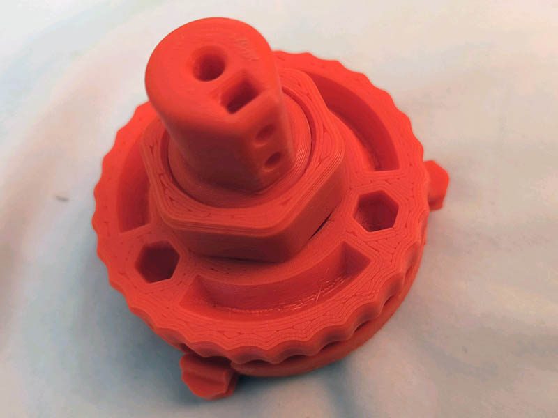
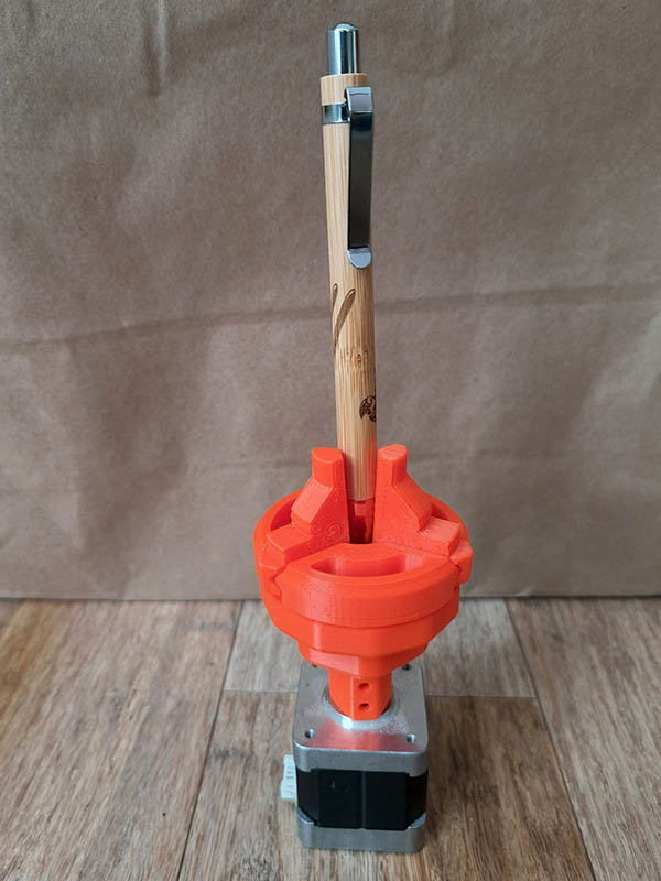
Here are a couple photos of the 1st test print assembly.
7 Likes
This is a little sloppy fit which I kind of expected, but more so than I thought. I added some more support for that inner gripper as that bent a little too much without that 45-chamfer added. I have a 0.2mm clearance on the jaw sliders horizontal movement & a 0.2mm backlash for the spiral gearing. I think the backlash is ok. The jaw sliders I am making 3mm thicker & adding 4mm to the height of the base of the chuck. I also changed the clearance of the jaw sliders to 0.15mm. I will have to file and sand these down some to fit smoothly. I had to file them down before but will have to do more this time. One of these days I will get a printer that can print with tighter tolerances. I am using a 3.5mm spiral pitch now as that looks ok when I print to spur gears with the numbers I used. The module size for the 3.5mm is 1.114085. With the 3.5mm spiral pitch, I am able to get the outside diameter down to 62mm with 4 spirals for the 3 jaws. I am printing the new version today.
7 Likes
I had to do some tuning to my printer this week as my prints were not coming out as well as I liked. I tightened the belts, eccentric nuts, changed the y-axis wheels to the Xtreme Solid V Wheels & changed my y-axis limit switch that was starting to misbehave. I also calibrated the x, y & z axis closer than I have before. It is amazing how much better the prints look now. I finally uploaded this design to thingiverse if anyone wants to try it. It is still a little sloppy fit but might be useful. I certainly learned a lot by working through this design. I have a new Atezr L2 24W engraver, so will probably switch to using their rotary attachment soon. Three Jaw Chuck with Spiral Gearing by GeoDave - Thingiverse
3 Likes