I’m using and autodesk education licence for fusion, and I just can’t figure out what I’m doing wrong, if I am not wording it correctly in my searches or if I’m just a complete idiot. I am new to all of this, first cnc machine built last month first time using any software(used fusion because it seemed the most feature rich and could get it for free) I have a box desinged finger jointed with just a grove for the lid to slide in and a pocket in the bottom for a led light to sit in. My cut area isnt big enought to cut all the components from a single sheet, but when I try to cut the individual components out the orientation is all over the board and I have no idea how to adjust it.
I set up the entry point in the bottom left corner of the piece orient x and y accordingly and some pieces gcode sends my router slamming into my left rail or sends my z axis up 6 inches. I have no idea what I’m doing wrong or how to make the adjustments I need. I have googled and watched youtube videos and I keep having the same problems I’m ok with changing directions on software or whatever.
Details are missing for me to be sure of what is going on. My best educated guess is that 1) you don’t have an independent setup for the pieces you are tying to cut out, and 2) you don’t have the orientation set correctly.
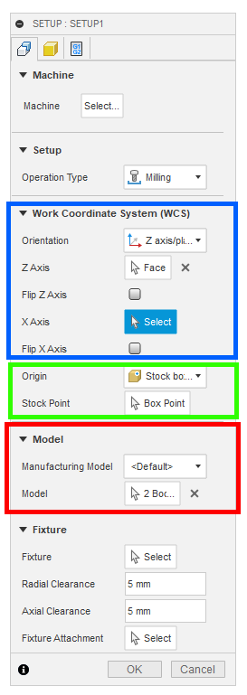
For each job, you want a an independent setup. You can have as many setups as you need, and each setup will contain the toolpaths for that job. So if you want to cut out two pieces, then those two pieces should be selected as the model (red rectangle below).
Next, you have to set up the coordinates to match the models. This is the blue box above. If you authored your models on the top plane, then you can often use “Model orientation”. If not, you will need to use selet the Z and X axes to match the orientation of your models.
Finally, you will need to define the stock point you will use as your starting point (green box). I always select “Stock box point” as the type. The position will up to you for your particular job. It is common to use the top of the stock and the lower left corner of the stock. For contour cutting, if your spoilboard is surfaced, using the bottom of the stock (i.e. the spoilboard) will result in less scarring of the spoilboard, but it is a bit more difficult to set up since you will need to home your machine against the spoilboard and not the top of the stock.
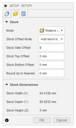
Then you will need to set up the stock.
Personally, I always use a Relative size box and either “No Additional stock” or I’ll add a bit of stock to the sides as I’ve done in the image above. By default, there will be some stock added to the top, so you will need to zero out that value. You don’t want added stock on the top.
Repeating, you will need to do a setup like this for every indepentent job on your machine.
Thank you for responding, I haven’t intentionally but have deleted and started new set ups. I even went to the point of importing an svg of a box just to have a single plane starting point extrude the first box piece and go into manufacturing. I change the origin to the highest z axis point of the bottom left corner of the box. I change the entry point to be the bottom left corner of the box I run the simulation and it enters in the bottom left of the piece I post the process take the g code to my machine and it acts like its setup in the middle of the piece and runs into my y axis of my machine. So I unplug, resetup my tool to the bottom left corner of my work piece manually g92 every axis to 0 in fluidnc, hit the go button on my gcode and it does the same thing. I will go back in and try again and focus on the instructions you just gave me to see if I can make any progress. I really do appreciate you taking the time to respond with some specifics.
If you want, save your Fusion 360 file to your harddisk, add it to a ZIP file, and upload it to a form post. I’ll load it and take a look to see if I can spot what is going on.
Thank you for trying to help me. I ran the setup following the instructions you gave me. I was definitely just doing setup settings in the tool path generator and not in the set up side panel, but I still have the same problem but in a totally new direction now.
I am attempting to set everything up to start in the lower left corner of my machine and for whatever actions need to happen move from there. When I run my code sometimes they start there and move right and up sometimes they try unsuccessfully to move left sometimes they move up in the z axis 5 inches and the most recent one I created after you showed me where I need to start my setup decided to move south in the y axis. So I have no consistency to how I screw it up. I am attaching the zipped file of my most recent start over and all I did was grab one piece extract it and move it to manufacture to attempt the gcode again. this is the one that decided the first move should be negative in the y axis about 5 inches when I anticipated positive in the x axis about 5 inches. Lighted box Project v1.f3d.zip (692.3 KB)
To start with, some of the struggles you are having can be eliminated by authoring your sketches (and therefore you models) on the Top plane (XY) rather than the Front Plane (XZ). The default settings (Model Orientation in the Setup) will match, so you won’t have to mess with the orientation.
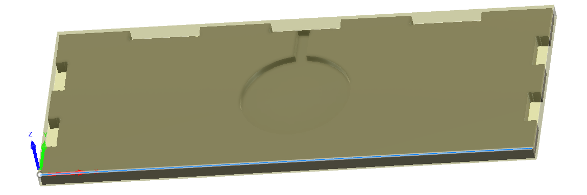
Assuming you want a “standard” setup of bottom left current at the top of the stock, you want the coordinate grid at the corner to look like this:
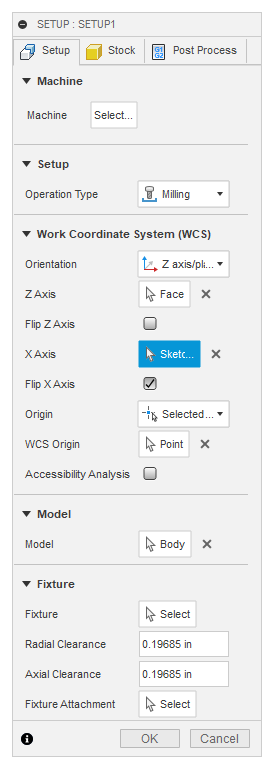
I selected the top of the model to be the Z plane, selected the front edge as the X axis, and then flipped the X axis. Note I don’t have an in-depth understanding of these settings. On the ocassions when I’ve needed them, I just play with the settings until the coordinates (blue, red, green arrows) match what I need for my milling operation.
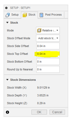
In the stock tab, set the Stock Top Offset to 0. The side offset will result in the milling beginning inside the stock rather than at the edge of the stock. This will help compensate if the stock is not mounted perfectly square with the machine. Alternately, you can select “No Additional Stock” and simply place the origin of your job (i.e. the tip of the router bit) slightly inside the stock.
Note these settings don’t explain all the behaviors you write about. Make sure you have established the origin of the job. On Marlin (and I assume on GRBL) you would execute an appropriate G92. Depending on your process, this can be done before you run your job, or it can be added to the start code of your job.
If you want to reauthor your sketches on the Top (XY) plane, you should be able to right click on the Sketch in the browser tree and use “Redefine Sketch Plane.”
Totally unrealted to the problems you are having here, but I wanted to mention that there is a Dogbone addon for Fusion 360. This will save you the time of squaring the corners of your joints.
Good lord I thought I was working in the xy plane the entire time, I hope thats all I did but I will make another attempt at it soon and let you know how It comes out. I greatly appreciate all of the time and advice you have offered up.
I did see the dogbone add-on, I guess I was just so frustrated with my getting my project orientation i hadn’t really looked into where to download it and how to set it up yet but it was something I planned to do for the corners. The svg file I’m working with now has the dog-bones in it not sure if they will come out like that or not though.
I missed that you already had dogbones. It will come out like that. The profiles for the tool paths will be taken directly from the models. Note there is nothing inherently wrong with authoring models on planes other than XY, it just makes creating your Setups more complicated.
I wouldn’t recommend it right now, but I wanted to let you know that it is possible to define your toolpaths directly from sketches, no models required.