I realise that I cut the feet support tubes for the MPCNC too small, they should be approx 6cm longer. Whilst I can buy more 25mm tubing, I wondered if I can print them out.
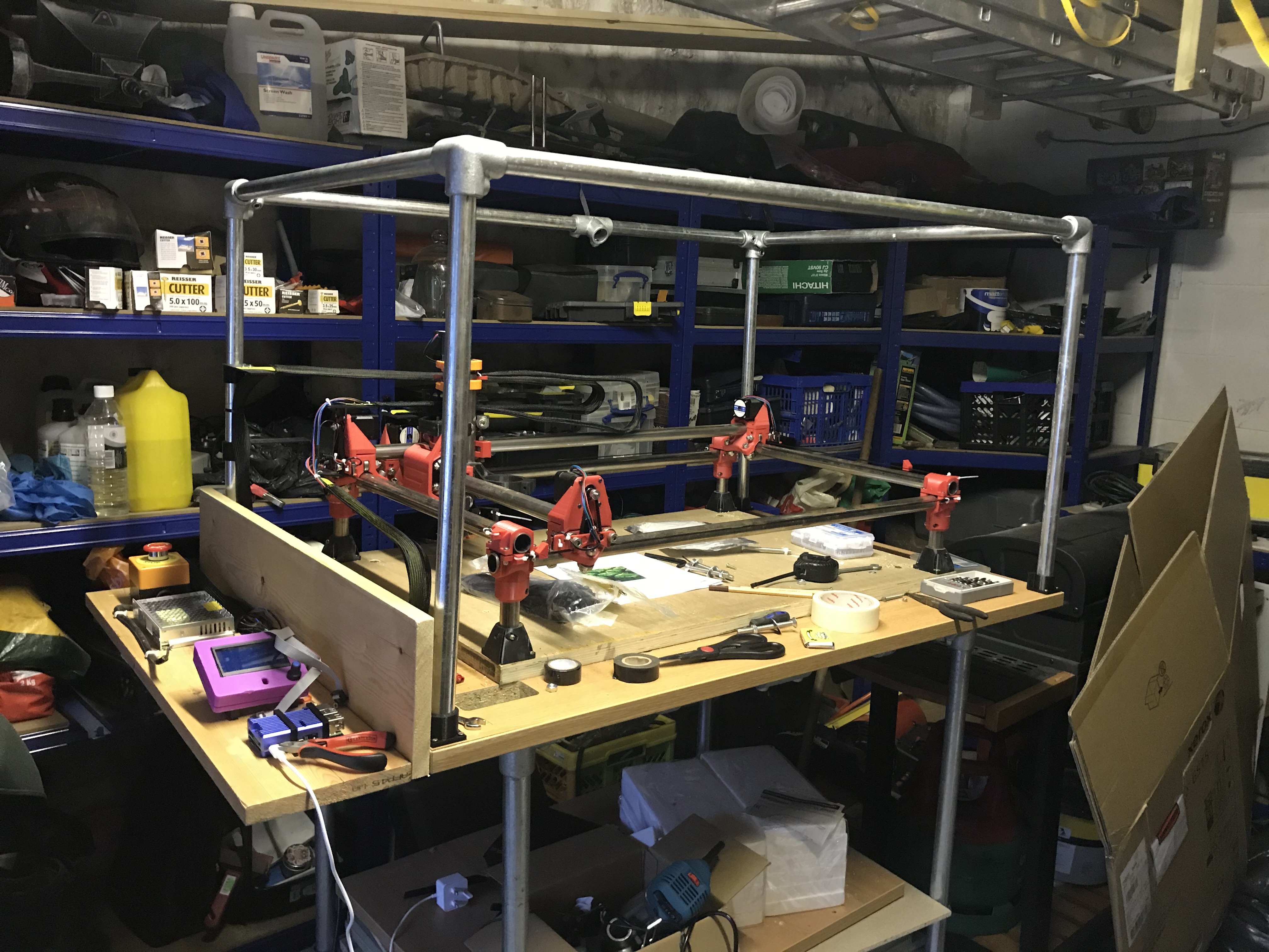
These are the tubes that fit into the MPCNC feet and raise the X axis and Y axis off the bed.
I would have thought 120mm long at 75% would be strong enough, but am happy to take advice.
I thought about the wooden spacers but it’s one join on another on another.
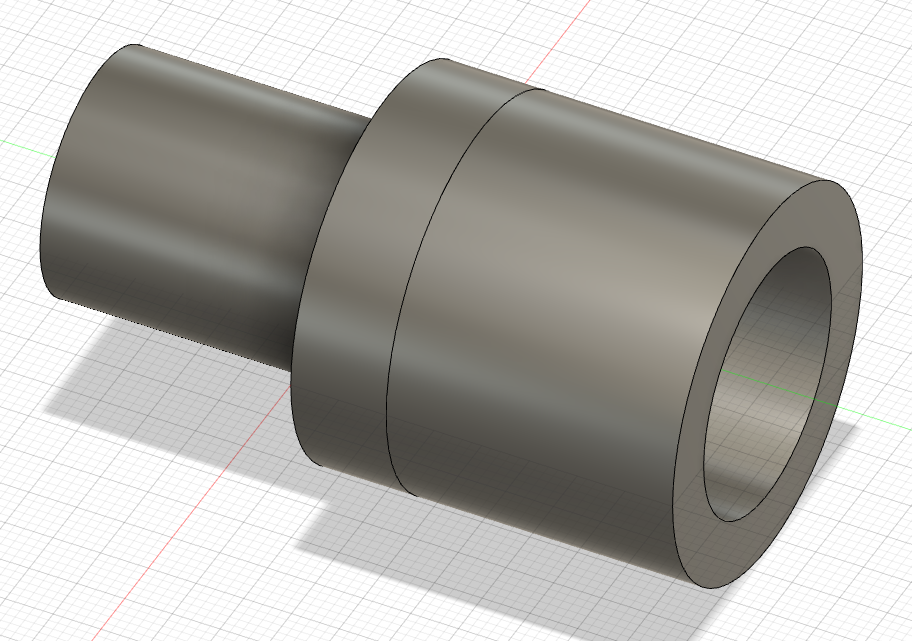
My other option is to use 26.9mm steel tubing and make a 26.8mm to 25mm adaptor. I have a few metres of 26.9mm tubing left over (which is one join on another on another )
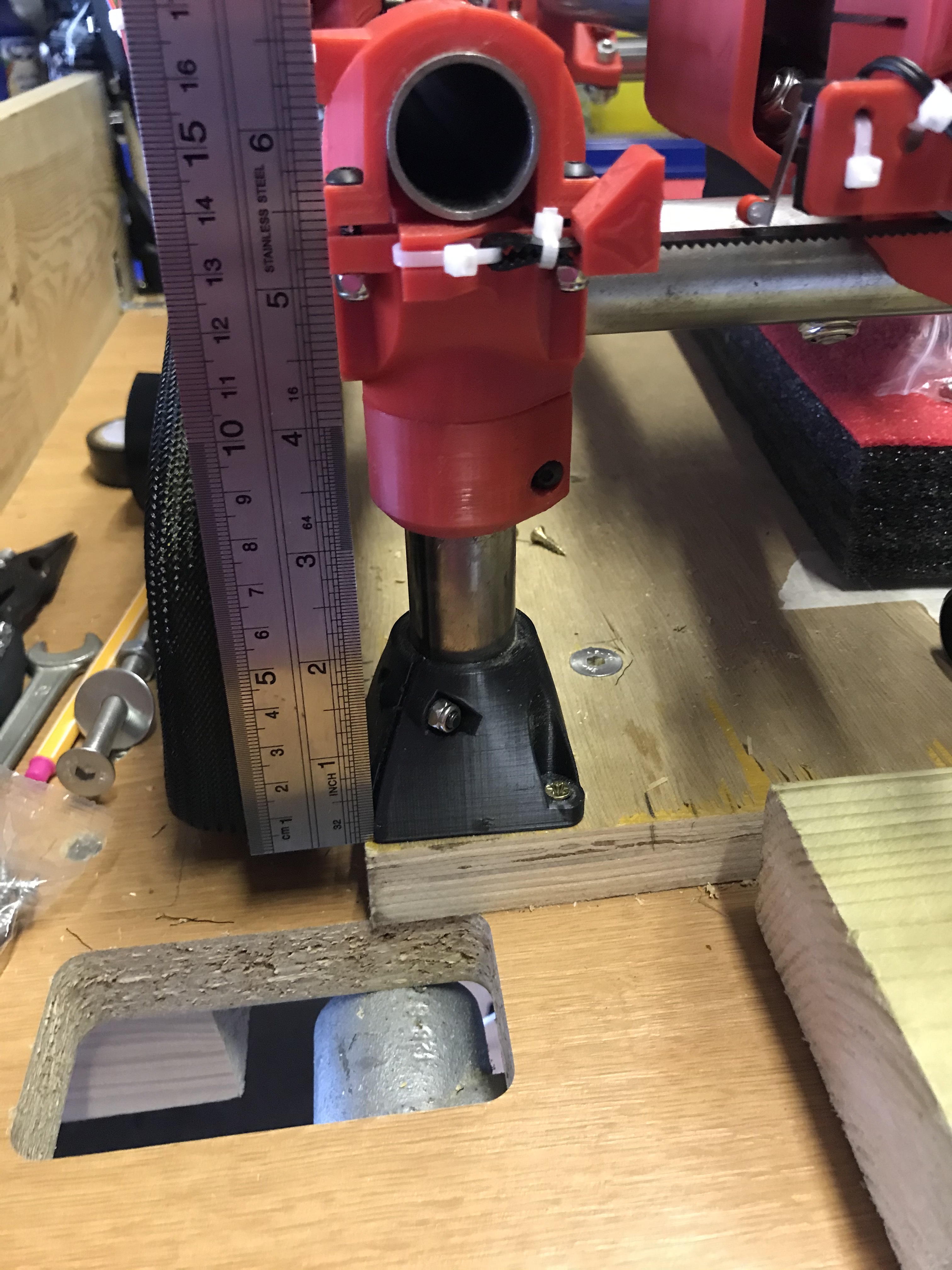
I am annoyed I got that calculation wrong, I didn’t take into account a spoil board, the length of the chuck/collet and the length of the bit. I’m lucky the router isn’t actually below the table
They’re 100mm high and I think they need to be 160-180mm. I just didn’t think about the router collet, the length of the router bit, the spoil board. Didn’t think that through.
Just checked on printing 180mm x 25mm x 75% infill legs (assuming they will be strong enough), just knocked it out in Fusion 360 and PrusaSlicer tells me it will take 11 hours to print, So two solid days for four supports. At 55% infill circa 10 hours each .
I think based on this, the best thing to do is buy 180mm x 4 steel tubes and wait for them to come by next weekend.
I can then lift the X and Y axis by pulling up to the separate metal frame that I’ve built for holding the vacuum hose, and then slot the new 180mm support legs in, so I don’t have to disassemble everything.
As it sits that is a pretty tall machine. I really do not suggest any taller. You can really only cut 3/4" with most 1/8" end mills.
If you are worried about putting large things in to cut, say a pre-built jewelry box or something you can cut a hole in the table to accommodate it (drop table).
Do you mean this is currently as tall machine? Or it will be a tall machine if I put an extra 60mm on the 100mm supports?
I do recall that there was a sensible upper limit. The stuff I’m cutting is 30-50mm foam so I’m not going to have much resistance. I wasn’t planning on cutting anything heavy, though I was trying to get this thing working for my daughters end of school year to do some plaques for all her year.
The problem with a drop table is the foam is deep, circa 30-50mm (1.25" - 2") and it’s large, 500mm or so by 400mm., so a drop table won’t work for me. I’m going to do some more measurements and work out the smallest size I can get away with, e.g. a 6mm spoil board would take 12mm out of the equation and then work out the smallest tolerances. I may be able to remove the spoil board all together.
I have looked at the router mounts and inverting them saves another 10-15mm.
However If you think the current size is as big as it should go, please say so and I’ll have another think.
Does anyone have a rough CAD model of the 660 (in STEP or IGES)? I’m in the process of designing my table/system and I don’t want to have a similar issue. Haven’t purchased anything yet so I can’t make my own measurements.
Thanks. I’ll study that a little closer. I’m working on a drop table design so I was trying to eek out as much working volume as possible. The calculator doesn’t take that into account but that’s understandable since it seems to be pretty rare. I’ll upload some screenshots to a new build thread once I’m at a good point in my design. I haven’t found any drop table designs (except a thread from 2018) so it looks like I’m playing off in the weeds.
 )
)