I suspect I’m one of the last people building and calibrating LR3.
So to recap:
I got squareness to 0.5mm and didn’t correct it with M666 because I do not exactly understand how. Does it matter which way it’s shorter by 0.5 mm? Should I then input 0.5 or -0.5?
Can someone explain with an example? Let’s say I have 3500 mm between (Xmax-Ymin) and (Xmin-Ymax) and 3500.5 mm on the other line across. What gcode commands should I then issue to make it better?
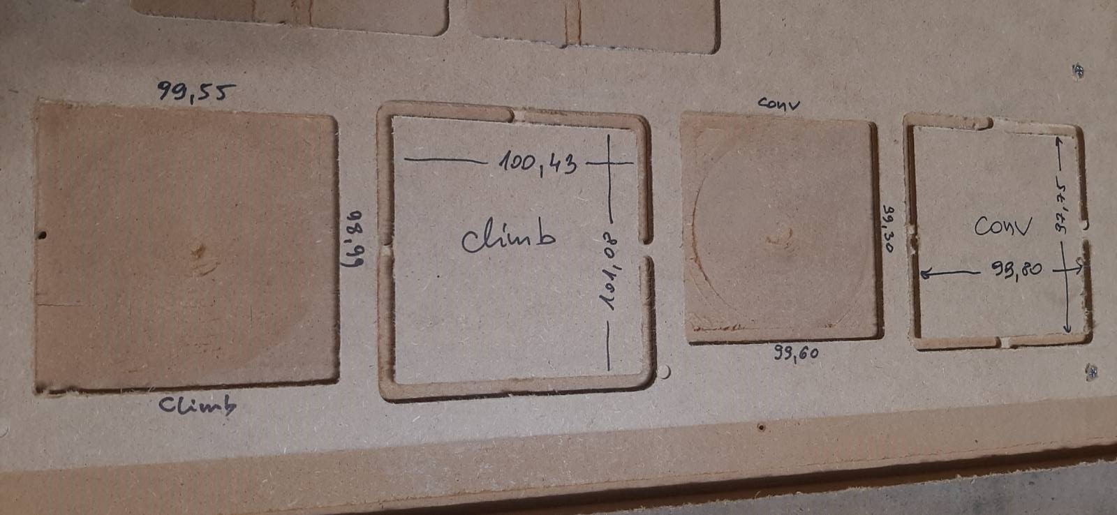
Anyway, I’ve cut 100x100 squares and they look like below. How good or bad it is on the scale from 1 to 10?
Can you please comment on those results and suggest how much better they should get for me to cut furniture parts and/or vcarves?
=== edit
Ryan said in previous thread:
“My second comment is the small squares are not all that great of a tool. The best thing you can do it mark out a full sized square with your machine. Then you can get the machine as exact as possible. Everything after that is just cut settings, perhaps a little tramming…if you need better than 0.5mm.”
As it happens I tried to cut much bigger square, so I will put measurements here tomorrow.
After that I will try to prepare table to mark 1200x1200 square with a pen and measure it.
I.am personally a fan of multiple sizes to calibrate.
One max size, as big as you can. This gives you the most accurate adjustments for dimensions and squaring. 1% of 50mm is 0.5mm, but 1% of 2200mm is 22mm. Much easier to spot, and the difference between 1% and 0.98% is possible to see on a tape measure.
So why multiple sizes?
Say you cut 500mm, 1000mm and 2000mm lengths. They come out in real world as 506mm, 1011mm and 2021mm. This means 1% +1mm. The 1% is probably steps/mm, or belt pitch, and the 1mm is machine flex, belt slop or tool size error.
If you are adjusting square only, one big rectangle (or 4 corners of it) is plenty good.
Over how long of a distance (diagonals) was this? 0.5mm over 100mm isn’t that great (measurement error and measuring tool granularity makes this small of a measurement almost meaningless)could . 0.5mm over 3200mm is quite reasonable.
Not too bad, but it really depends on what you are trying to fit together. A little sandpaper can make parts that are pretty close become just right. This isn’t a $10k machine, so you can’t expect 0.0001" tolerances, but you can probably get things within +/-0.3 to 0.5 mm fairly easily.
Did you do a finishing pass? That can bring tolerances a bit closer.
Your holes are a tad bit smaller than specified, and your parts are a bit larger than specified. You might try redefining the bit size in EstlCAM (try 3.00 instead of 3.18) and see it that makes things closer.
You have a very small bit of difference between the X axis measurement and the Y axis measurement on both Climb and Conventional. You may want to check to see if there is any looseness in the core (will it move up and down if you try twisting it or lifting it with your hands? Are the bottom rollers spinning loosely, or are they dragging against the lower rail?) But for many applications they may be alright as it is.
Once you have things where you are happy, I suggest doing some test cuts with whatever material you are planning to use for your cabinet/furniture. You may find that it behaves a little differently than hardboard.
Yes, I did! Material was 3.2 mm thick, I did 0.3mm finishing pass.
It was 6mm bit, and I measured width of cut on those, and on the climb one it’s very close to 6mm, but on the conventional ones it’s closer to 6.5mm. What does this mean?
For calibrating the kinematics you want to use a v bit or pen to just poke/dimple tape via a downward Z movement after the xy moves. Cutting throws in a bunch of other variables that you won’t be able to separate from each other.