Calculating cutting area dimensions for build using DWP611

Thanks in advance for reading and to those who can help me out!

I’m looking to get a cutting area of 24" x 36" using a Dewalt DWP611 since it’s what I’ve got sitting around. Understandably, the calculator on the website for the MPCNC doesn’t include an option for this.

The diameter of the router is 69mm at the lower and the top goes out to about 90mm, with the power cord coming out perpendicular. I’ve seen other builds using this router but no information about how they implemented it.

How should I go about selecting my material length for my XY rails? Will the extra weight cause rigidity issues or sag when it sits center of the machine with the size of the proposed cutting area?

Thanks again for your time.

Have you looked at the low rider? It uses that router. That is on the small side for a LR. But it will work great.

1 Like

I started to answer your question earlier, and then stopped. I don’t know if the top 90mm portion of the router will hit the end before your trucks do, so I’m unclear about how much to add (if any) to your cuts size. And, I’m unfortunately away from my machine, so cannot take a look. If you add 25mm to the length and width of your cut calculations, you will be guaranteed to preserve your full cutting area. You may have to redirect your power cord. I had to make this change for my Makita router. There are 90 bends for the cord on Thingiverse.

As for your size, you are on the larger end of the acceptable range for a MPCNC Primo. Based on forum posts, your machine will do fine with softer materials like wood, but you might struggle with something like aluminum, and you may have reduced cutting speeds compared to smaller machines. The longer outer rails might benefit from a mid-span support (several posted on Thingiverse), and, given the size, you might be happier using 1" stainless steel or DOM tubing instead of conduit.

Thank you guys for your replies! I was thinking of just adding 2.5" each to X and Y axes, and figuring out how to do the mid-span supports. I wasn’t aware of possibly needing to redirect the power cord. I’ll cross that bridge once I get there.

Adding 2.5" seems like a lot…and I would avoid adding that much to the longer axis if it was not necessary. I’ll be home on Sunday and can a closer look at my machine and give you a more informed opinion about how much extra you need…if any. Increasing the diagram of the tool by itself does not require longer rails. It simply shifts the position of the spoil board. You start having to increase the size when the mount is large enough to impact the sides before the trucks do.

The DWP611 has been mentioned a number of times on this forum, so I’d hoped one of the owners would respond to your question. I know the DWP611 was difficult to find for the last couple of years, so most people have purchased the Makita RT0701 instead.

If you search Thingiverse for “MPCNC mid span,” you will find a number of mid-span supports like this one. There are drawbacks to using mid-span supports, and you may not need them. They make it more difficult to slip stock into the machine and to mill oversized stock.

I looked on Thingiverse for the fitting to redirect the power cable on the router. I could not find it, and I could not find any of the other models by the author either. I wonder if the author has removed his models from Thingiverse. I likely still have the models on my home computer.

1 Like

Cool, all that would be very helpful if you could take a look and maybe find those files. I’ve just been seeing people turning their whole router spindle 90 degrees instead.

I haven’t cut my rails or made my table yet out of caution towards rigidity. I want a cutting area of 20 x 30 minimum or to go as big as I can with mid-spans. I bought two 3-foot pieces of 7/16 ready rod to make the mid-span supports from thing:1969520 on thingiverse (I can’t include links on my posts for some reason). Otherwise I have a 6-foot piece of 3/8 ready rod to make for a different mid-span support.

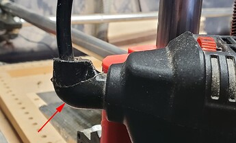
Home a day late. I just looked at my machine. I have a Makita RT0701C clone (Carbide 3D) router with a 65mm Primo Makita mount. With your larger router, there are two areas to look at. The first is where the “mushroom” head potentially intersects the bolt. The issue is here:

My clearance is tight at this point with only a couple of mms to spare. Placing a photo of both routers on top of each other in photoshop, the mushroom heads look very similar in size. Whether you have to add additional space for the head will depend on its geometry, but if you do, it won’t be a lot.

The second close place is where the mount intersects the tubing when the gantry is pushed against the trucks. Here is a photo looking down.:

There is probably 5mm of space left using my Makita (65mm) mount.

Looking at these two spacings, you should be fine if you pick the size you want your cutting area to be, then add 3/8" (10mm) to the measurements before feeding them to the MPCNC cut calculator.

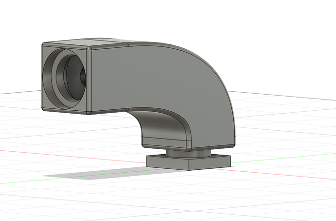
As for the fitting for the router, it could not find the model, but it is pretty simple:

Simply crack open the case at the top, slide the rubber fitting out of the way, sandwich the cord between the 3D printed parts, and reassemble the case to hold everything together. Personally, I did not even remove the rubber fitting, just slid it down to the plug end. That way I can reverse the process if I want to use the router more traditionally in the future. If you like, I can model up an STL of this part for you.

As for the mid-span supports, you will only use a few inches of rod for each support, and you will only need them on the long sides. The mid-spans you find on Thingiverse will be modeled for a specific threaded rot since you will need a nut trap for the inside of the tubing.

Awhile back Ryan ran some tests comparing different tubing. Over a 4’ length (longer than you need), he was getting about 1mm of flex with stainless steel tubing, and 0.5mm in DOM tubing. This movement was with a 10lbs weight applied, which is more than your Z axis and router will weigh, and your machine will split that support between two tubes.
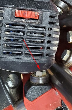
Neat. No worries, I still don’t have the time allotted to get this done. I really appreciate your help! I might design my own part for redirecting the cord that incorporates that sheath as it’s pretty big and unwieldy on the DWP611. I won’t be able to hide it inside the router, and it’s not removable unless I cut it off or remove disconnect the cord.

Just to be clear, it is big and unwieldy on the Makita as well. I did not hide it inside the router. After opening the case to release it, I simply pushed the sheath down the cord until it was near the plug, then installed the 3D printed parts.

Ohh okay I must have misread that part then. Yeah I could just rip the tag off the cord and slide the sheath down, too. But I’ve still gotta get a part designed so I might as well go all out.

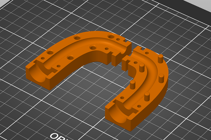
This is what I’ve got so far - I need to split the body and do extrusion cuts for nuts and bolts on the sides. I made it as square as possible so it will print without supports. Everything’s parametric so I’m almost ready to start doing test prints to fine tune and possibly have it ready to change parameters for other similar routers.

1 Like

Looking good. At one point I thought about replacing my sleeve. The one I printed off Thingiverse does not hold together very well and I ended up taping it. I suppose I could glue it, but I like things I can easily disassemble. My thought for my version was to put a groove on three sides at both the “top” and the “bottom.” This would allow me to hold it closed with small zip ties (like the ones from Dollar Tree). The buckle of the zip tie would rest on the one side without a groove. That side would also be the one on the build plate when 3D printing.


I’ve got it done now, I have to wait to print it until tomorrow when I can run my spool out and change filament during the print. I’ve got it set up for M3 screws and it’s easy enough to just extrude cut some slots on both ends of each piece for zip ties instead. I can also enlarge the ring section that the router shell clamps around so that placing the cap back on will tension that end of things without any fasteners.

It should be easy to make the parametric adjustments, so all that’s left is trial and error.

1 Like