There’s a fairly standard method for making an inverted countersunk hole, but running a couple of tangents on one layer, then a couple the other way on the next - some even truncate those again, but I’m not that convinced it’s necessary. I think you do this @vicious1? I know Prusa does, and Makers Muse did an entire video on how to draw it a year or seven ago.
I’m not sure if this will make a lot of sense but I do know what I’m trying to say!!
A conversation on another thread about mate connectors and assemblies in CAD got me thinking.
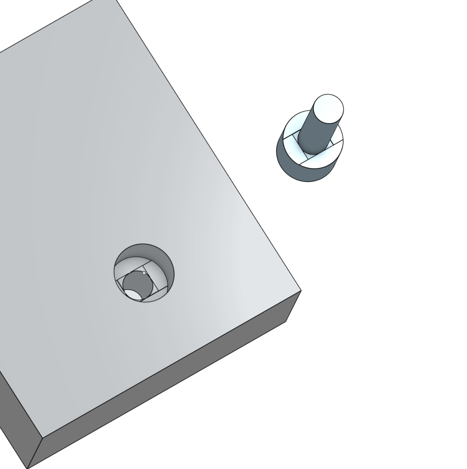
What if I was to draw a parametric “bolt” to make a pattern?
All I’d have to do would be to pop a mate wherever I needed that feature, stick the “bolt patterns” in place and do a boolean subtract. Someone way smarter than I could write a feature script in Onshape to fully automate this and it could be a one-click sort of adventure.
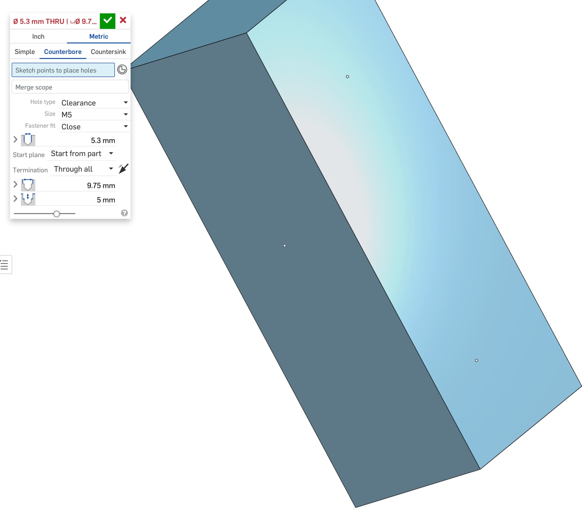
Hopefully this single screenshot will explain - if not I’ll publish a sequence.
Does this make sense, or is there a simpler way of doing this that I haven’t discovered?
I’ve had a quick look at what it will take to make a feature script library so it could be accessible to other Onshape users, and I may even be able to nut it out eventually - that would be cool!
Well I just moved over to orca slicer and it has a feature to recognize holes and basically does round bridges from the outside in. Those features are even needed. works really well.
The subtract idea is a good one, save a couple steps for sure. For me it is one sketch with both circles and the 4 tangent lines, through hole cut, counterbore cut, bridge cut one, bridge cut two. For a subtract you will need to add the part, size it, locate it, subtract it. Looks like it saves a step if locating is only one step.
At some point I got tired of it and I just cover the whole hole with 0.2mm layer. It bridges across and I use my massive ape arms to push a screw threw the plastic.
I’m pretty sure I copied it from somewhere. Not my idea.
I also use a single layer over the whole hole if the part is just for me, but most things I draw end up on Printables so I try to make them absolutely idiot proof, so I take the extra effort but mostly I avoid holes!
If I can do what I am proposing is a feature script that mimics the hole tool but with a custom countersink.
Future @vicious1 will only need to locate the centre point on the surface of where future penetrations are wanted and click.
Maybe I don’t use holes like this enough to warrant it, I certainly don’t have an aptitude for scripting, but it seems like something I’d like to have a go at one day.
Maybe just a script to add the features to a cut circle? Click on a circular face, make face down printable, 0.4mm cutbacks?? Maybe even add it like a polygon.
It’s easy to then select the faces and I think it should be relatively easy to make that “apply face” work - I’m sure it would be for someone who knows about this stuff, but I’ll see if I can get a chance to have a go over the next couple of days.