Hello!! I’m in the process of finishing building my first polar table. I’ve built the mechanism and most of a laser cut exterior for the table, but I’m not sure if I’m completely satisfied with it. I’ve got two parameters for a “good” exterior:
Slimness. I want to achieve a thin exterior so I can maximize the drawing-area to table-area ratio for aesthetic reasons.
Strength. I don’t want the exterior to feel flimsy or cheap, yet fulfilling parameter 1 usually leads to a thin/cheap-feeling exterior.
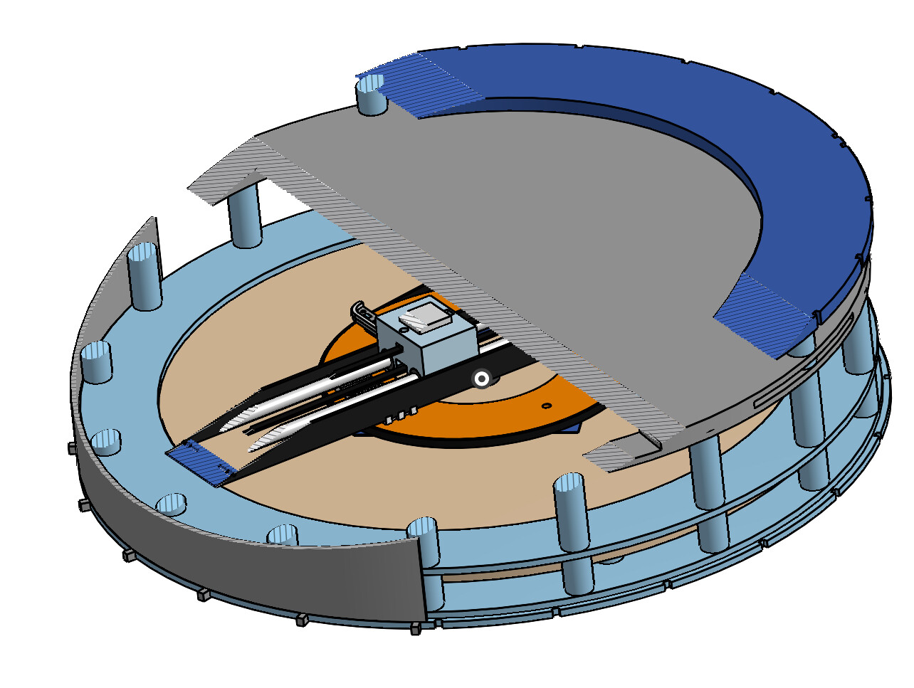
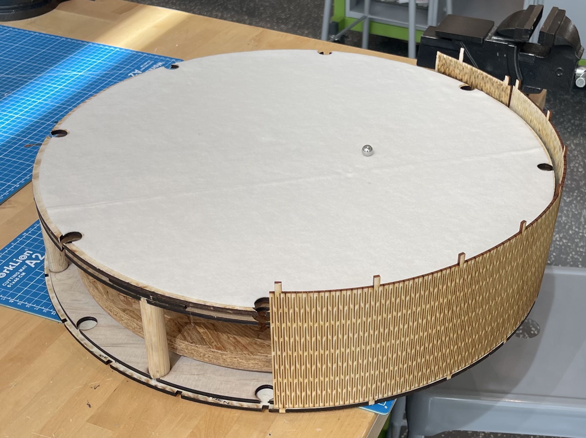
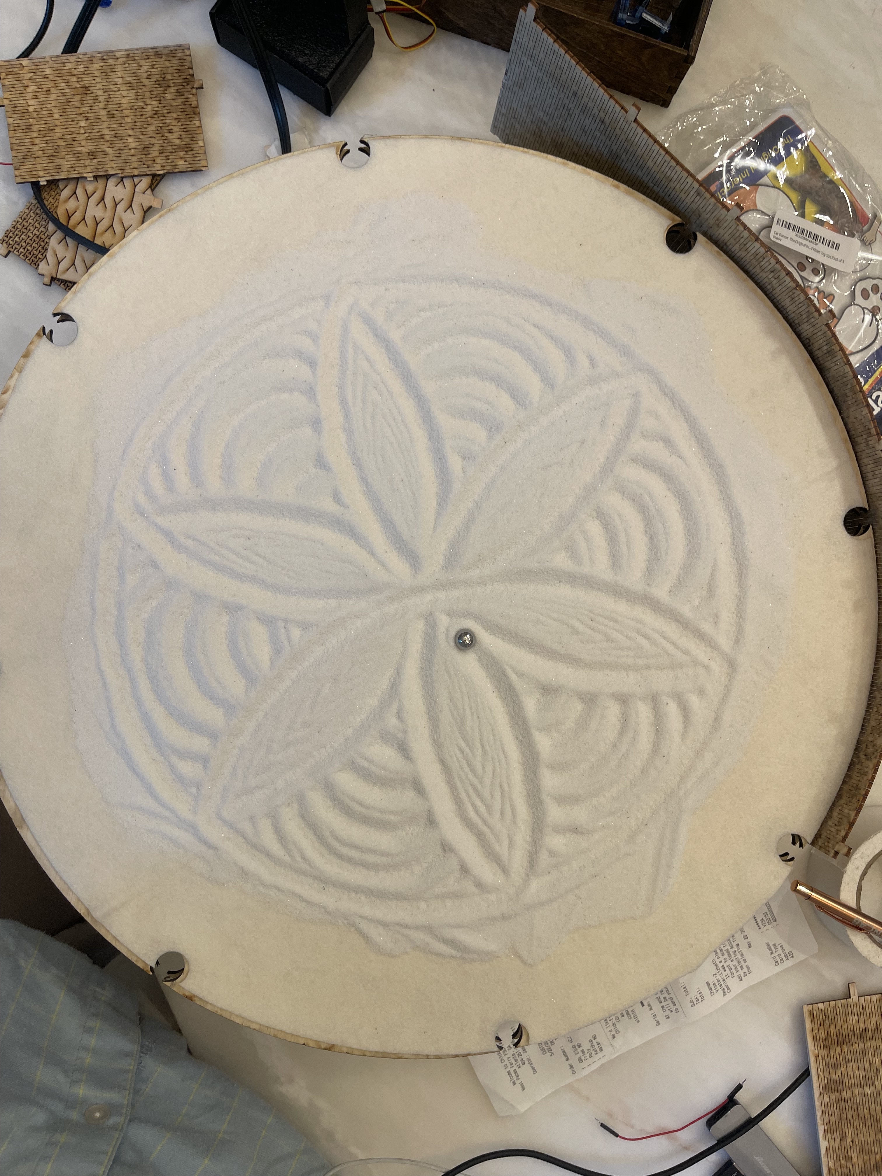
My current solution is made of laser cut wood and dowels that are wood glued together. The exterior lining will be three sheets of 3mm laser cut wood so it’s bendable and it snaps into the base and top of the table with little pegs. I’m also considering wrapping it with a veneer. Here’s a couple images:
I don’t get a large drawing radius with this, however. But I think this is mostly due to my current mechanism which I’ve since redesigned. My main qualm is how cheap it feels, it’s almost like a snare drum when you tap the side and I think it’s amplifying the sound of the motors.
My favorite example I’ve seen is the Ampersand by Moving Pieces but I have no idea how to make such a concrete mold for fairly cheap.
If I can get my hands on a CNC router I could also just layer a bunch of thick layers of plywood and it’d satisfy my requirements but it could also be pricey in terms of wood waste and I don’t have a huge budget.
I’m mostly just curious what solutions people have found for their polar table exteriors!
Haha yeah I’m pretty new to making stuff but I’m working on getting access to one at a makerspace near me so fingers crossed!
Speaking of which I literally just had a shower thought… if I just cut the layer circles as let’s say quarter or eighth circles on the cnc I could easily lay out a bunch of them on a single half/quarter inch sheet of plywood and just glue all of them together… this seems like a pretty appealing solution and it could def have a cool look if I rotated each layer by like 10 degrees as I stack them.
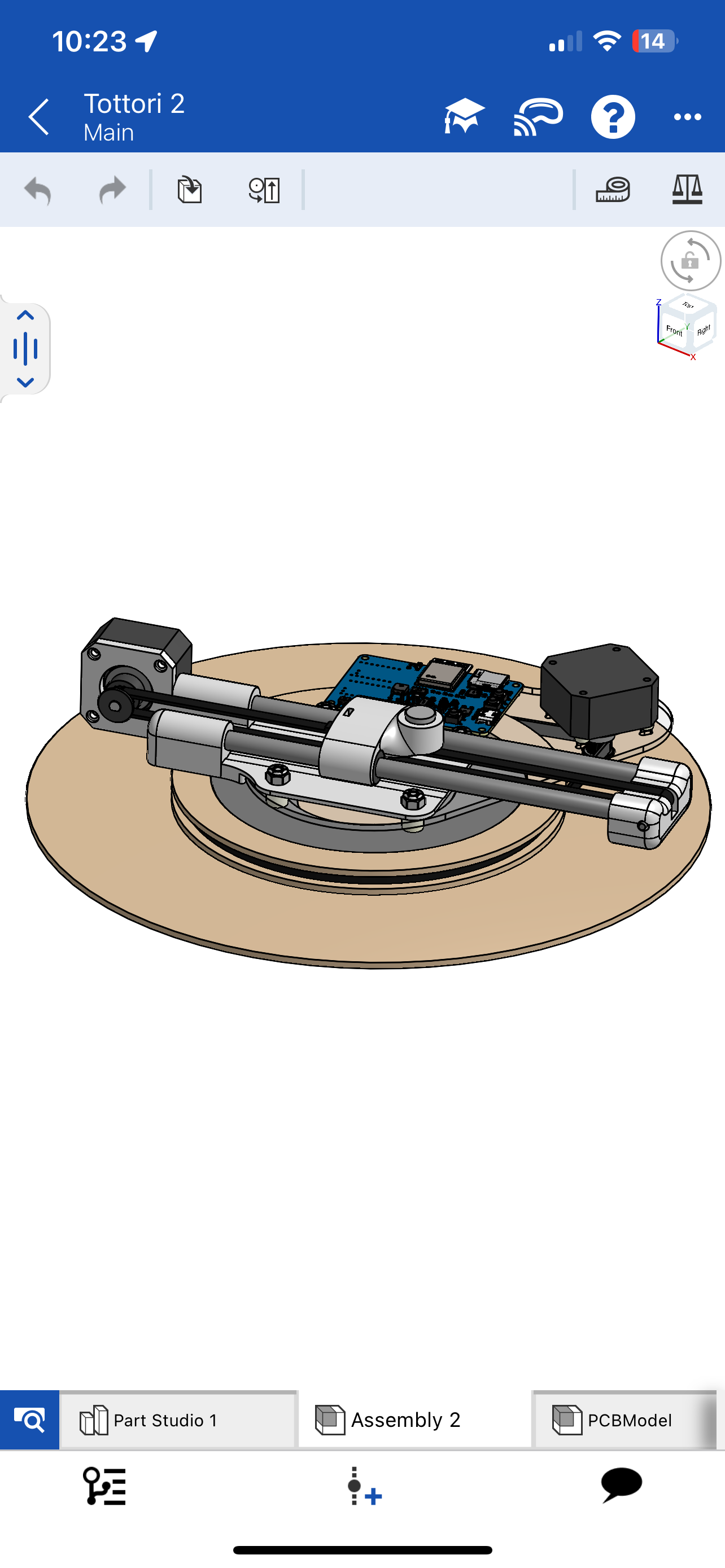
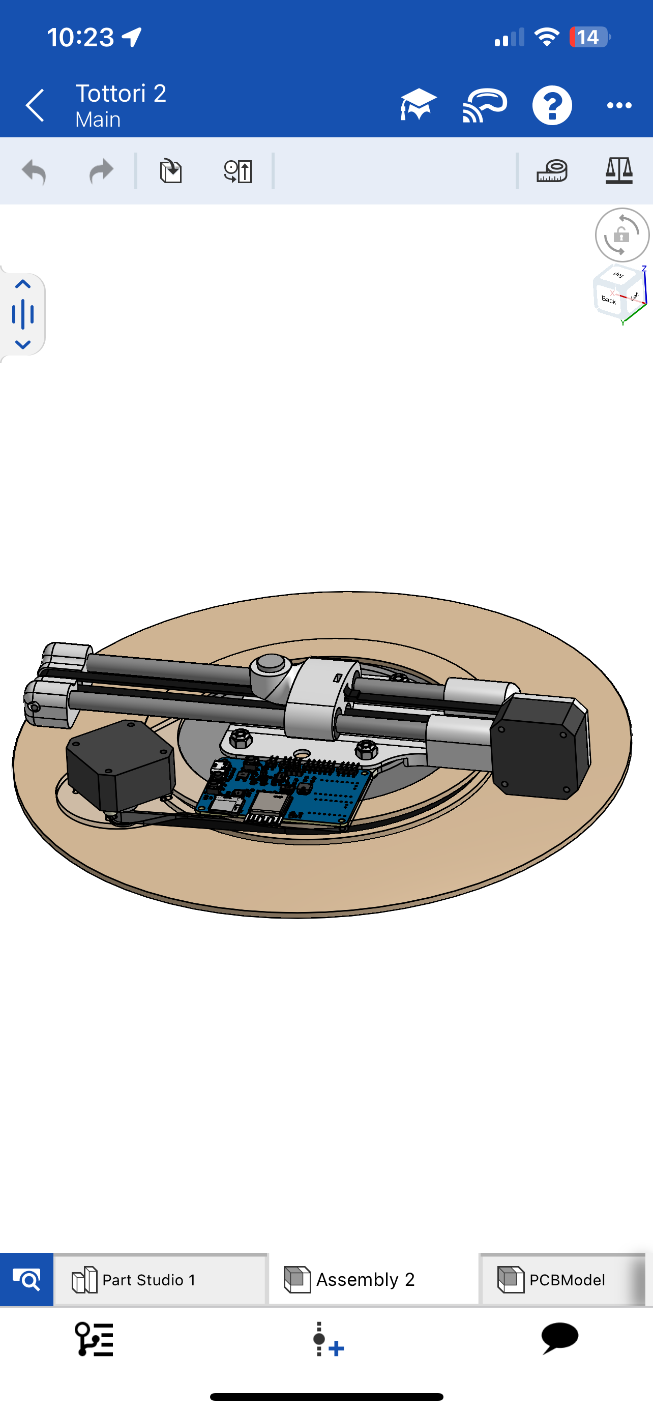
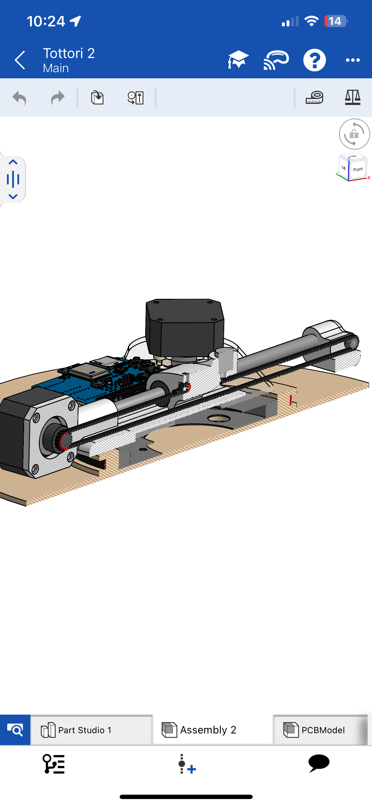
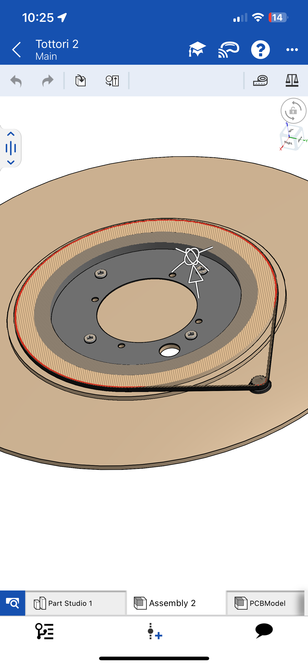
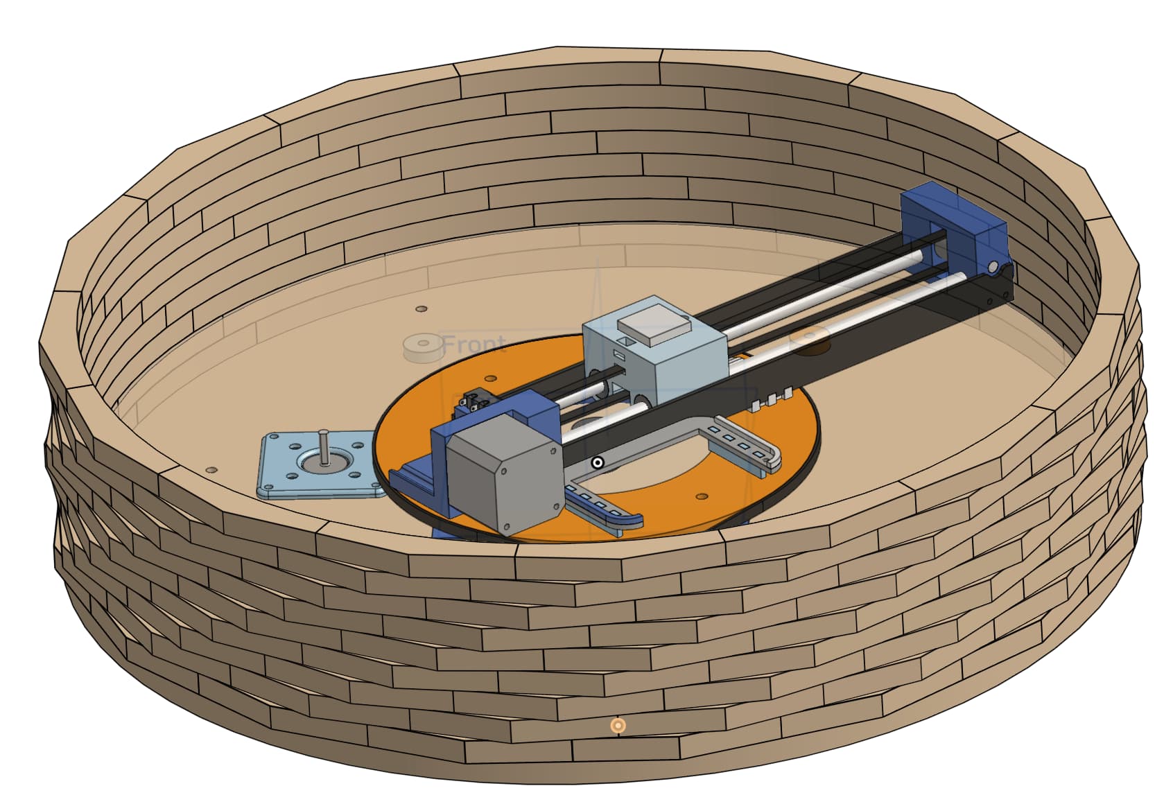
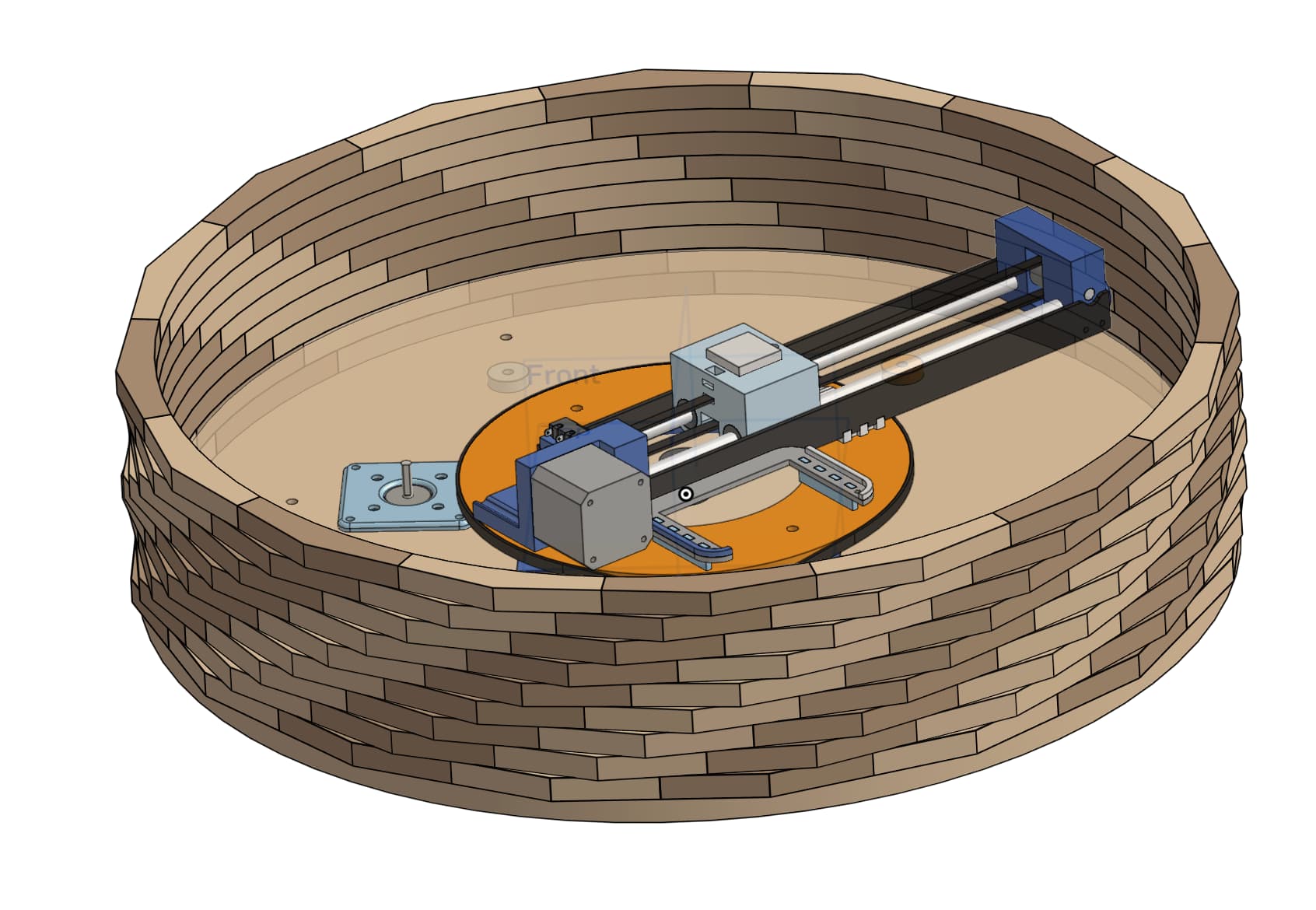
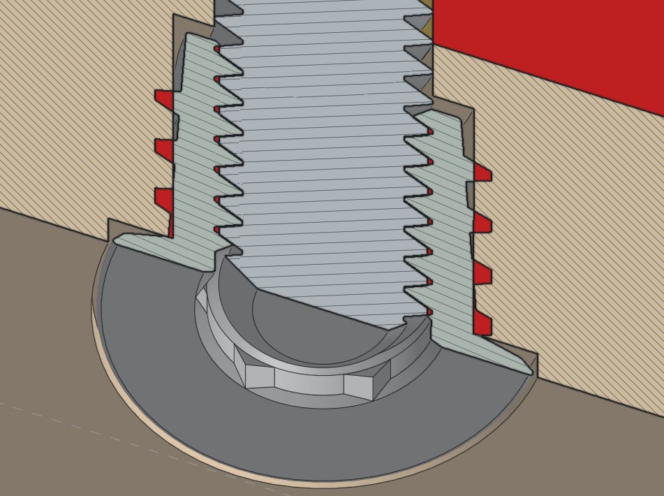
Now about the redesigned mechanism. I wanted to significantly reduce the height profile on this one so the table would look more like magic instead of hiding a bulky robot. I primarily did this by flipping the rotation motor upside down and attaching it to the rotating platform as it rotates against a stationary gear. I’ll have to do some testing to see what gear ratio works so it still runs fast without overloading the nema-17 but if I can find the time and also get access to the maker space’s laser cutter I could start making this in a few weeks.
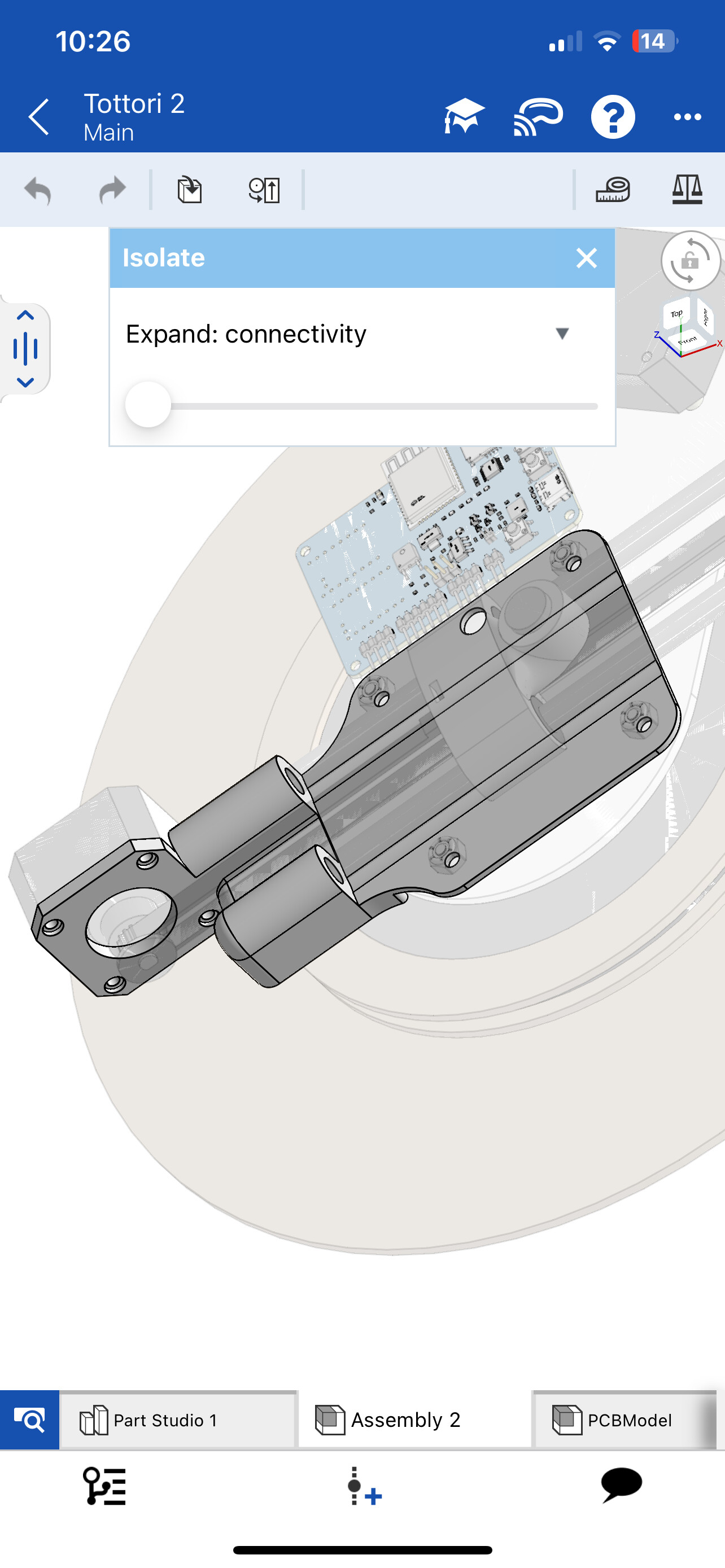
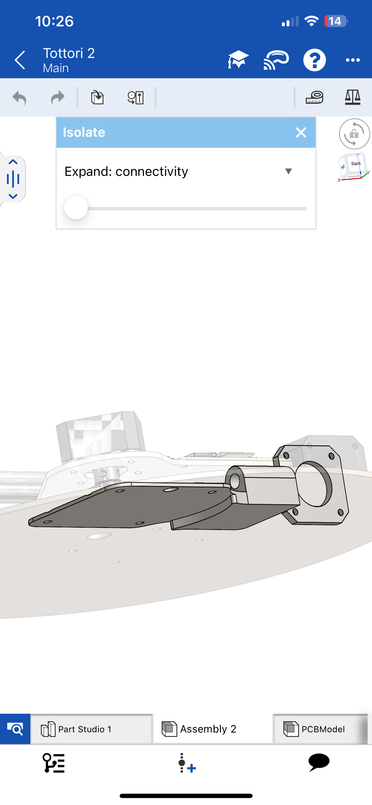
I cadded a good chunk of this on my phone using the onshape mobile app while I was at work since I’ve got a good deal of free time on the job (I should probably start bringing my laptop). I want to move the magnet a little farther out so it’ll have a slightly larger radius, add limit switches for distance and rotation, and see if I can redesign that center 3D printed piece cause it’s a pretty large one that might be somewhat laser-cuttable but I’ll still need a 3D printed bit so I’m now thinking of ways to combine laser cut parts and 3D printed parts. Will be a bit tricky though since this part is pretty load-bearing. Anyways here’s a bunch of screenshots!
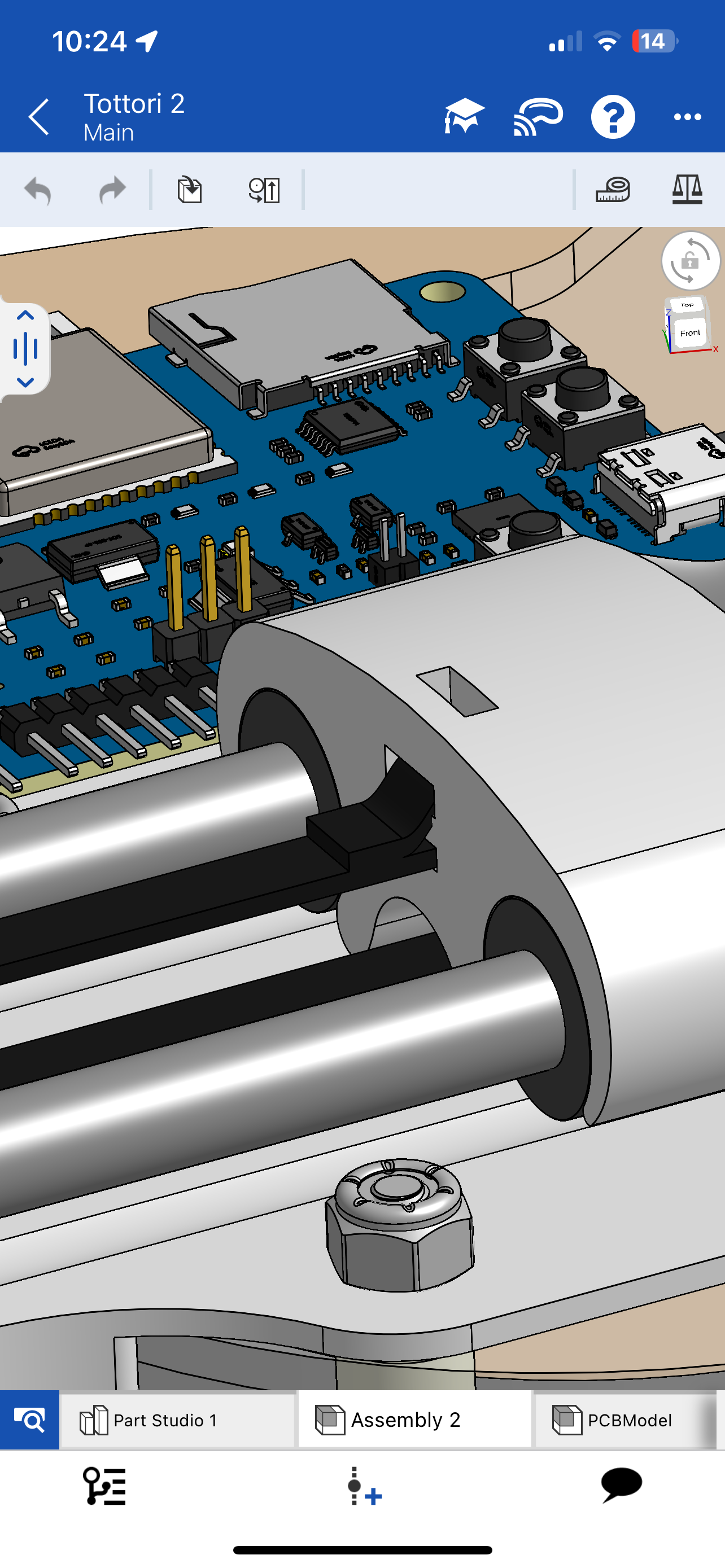
The magnet pushed all the way up against the end of the axis so it can get a larger drawing radius (still need to adjust some of the clearances on this):
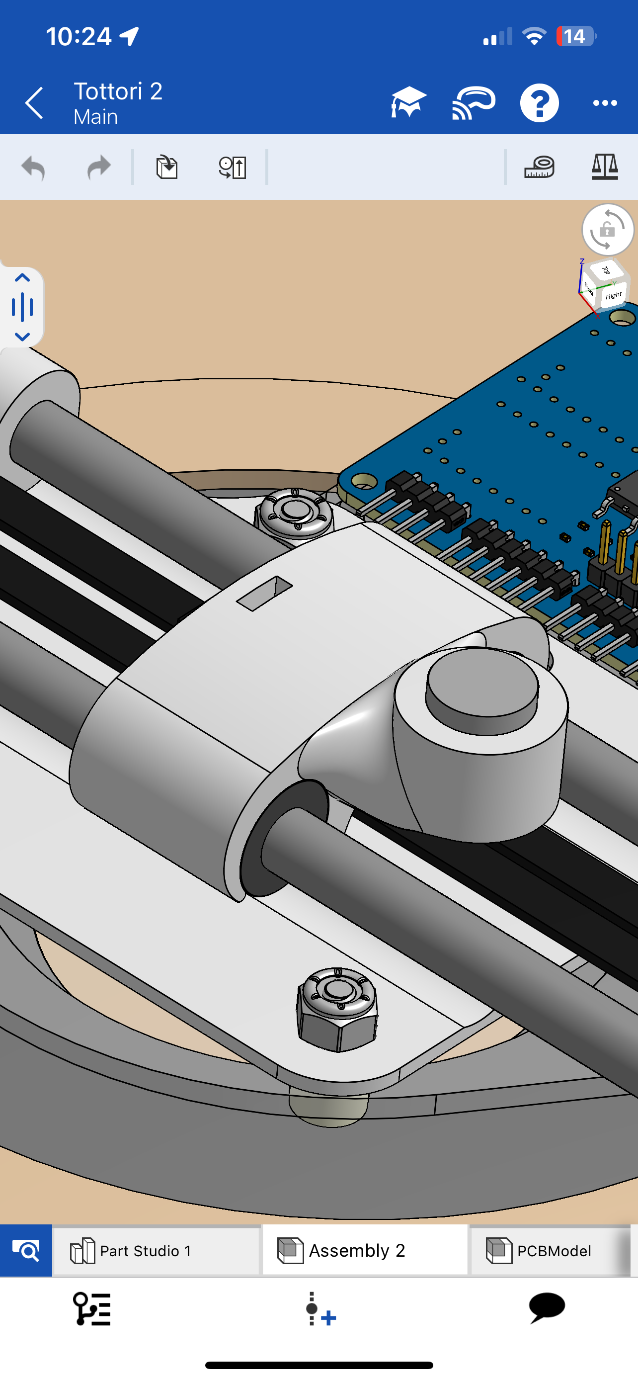
I also wanna see if there’s a way I can support that central axis better because right now it only has the two points of contact near the motor. It may not be a problem now since the design is only for a 12 inch tabletop robot but if I’d like to expand it to a full table I’d expect some changes will be needed. There’s some 12 inch lazy Susan bearings that I’ve found on Amazon that I could definitely try to utilize for greater stability if I ever redesign it again for a larger size.
I’m too tired and lazy to proofread this so don’t hesitate to ask any questions on my hopefully coherent ramble!
I’ve seen this done before. It will be the cut showing now. So a laser will be the burnt edge. A CNC would be showing end grain. You’ll want an engineered material (plywood or mdf) so the wood doesn’t bend and stretch during the seasons.
The other polar tables I have use steel (for the sisyphus) or molded plastic. Neither are easy for DIY machines.
Have you seen the parts on the MP3DPv5? It uses aluminum on the outside and printed plastic in the middle to do all the complex geometry.
Thanks for sharing. This is looking good. Where is the slip ring to get the wiring to the moving motors?
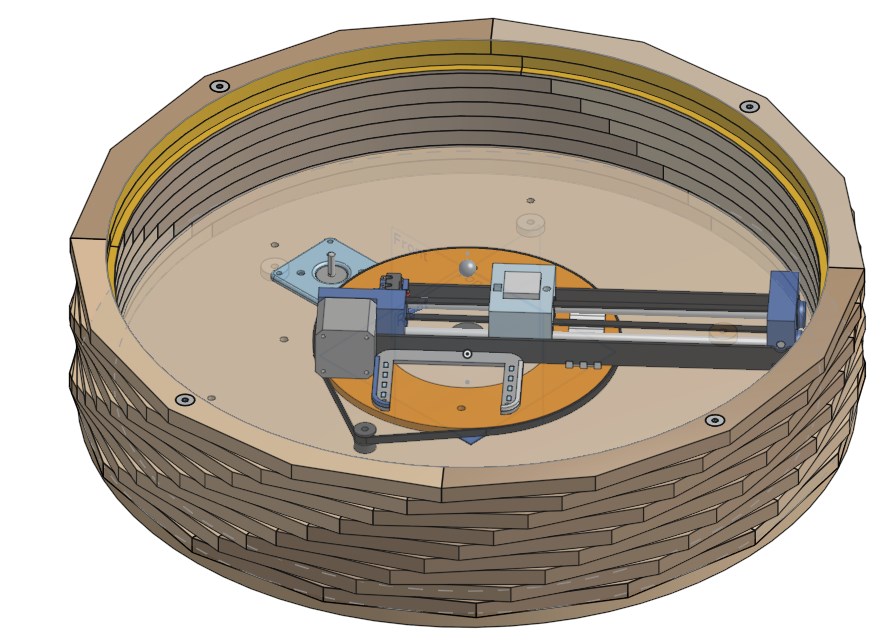
Thank you, I think this could look pretty cool! I’ve since cadded this (on my current v1 table and thank god not on my phone this time) and I think it looks awesome!! I originally made it circular, but it took onshape a while to load and it gave me a polygonal preview first without rounded circles. However, I thought this polygonal preview actually looked cooler than just being circular so I decided to take a polygonal route!
Just checked 'em out, I’ll give it some thought, and if I can get access to a cnc, metal capabilities will definitely make things easier!
Haven’t cadded it yet but It’ll just sit in the middle, I made some channels for wires to go in the laser cut parts. I think I’ll use a 6-wire one I found on amazon: 2 for power, 1 for the LED strip signal, 1 for sending 5V back down for the LED strip and rotation hall effect sensor, and 1 for the hall effect sensor signal, and the last wire will probably be for the BLE pairing button for the mobile app on first-time setup.
It’s surprisingly functional! A little unintuitive at first (like tapping with two fingers to open the right click context menu) but hey theres only so much you can ask from a mobile cadding app. It also appears to have Apple Vision Pro capabilities for viewing workspaces.
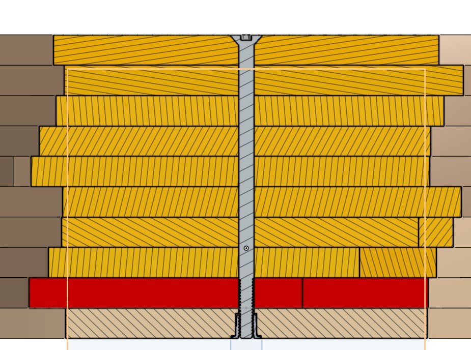
Quick update on this. I realized that putting this together would be a pain with 16 different sections for each layer, so I instead changed it to 4 sections with the same number of exterior polygon edges, and I added some 5-in screws (thank you mcmaster-carr) with threaded inserts at the bottom to go through the whole table so I can align them perfectly and might not even have to glue? Not sure but it’ll make assembly much easier.
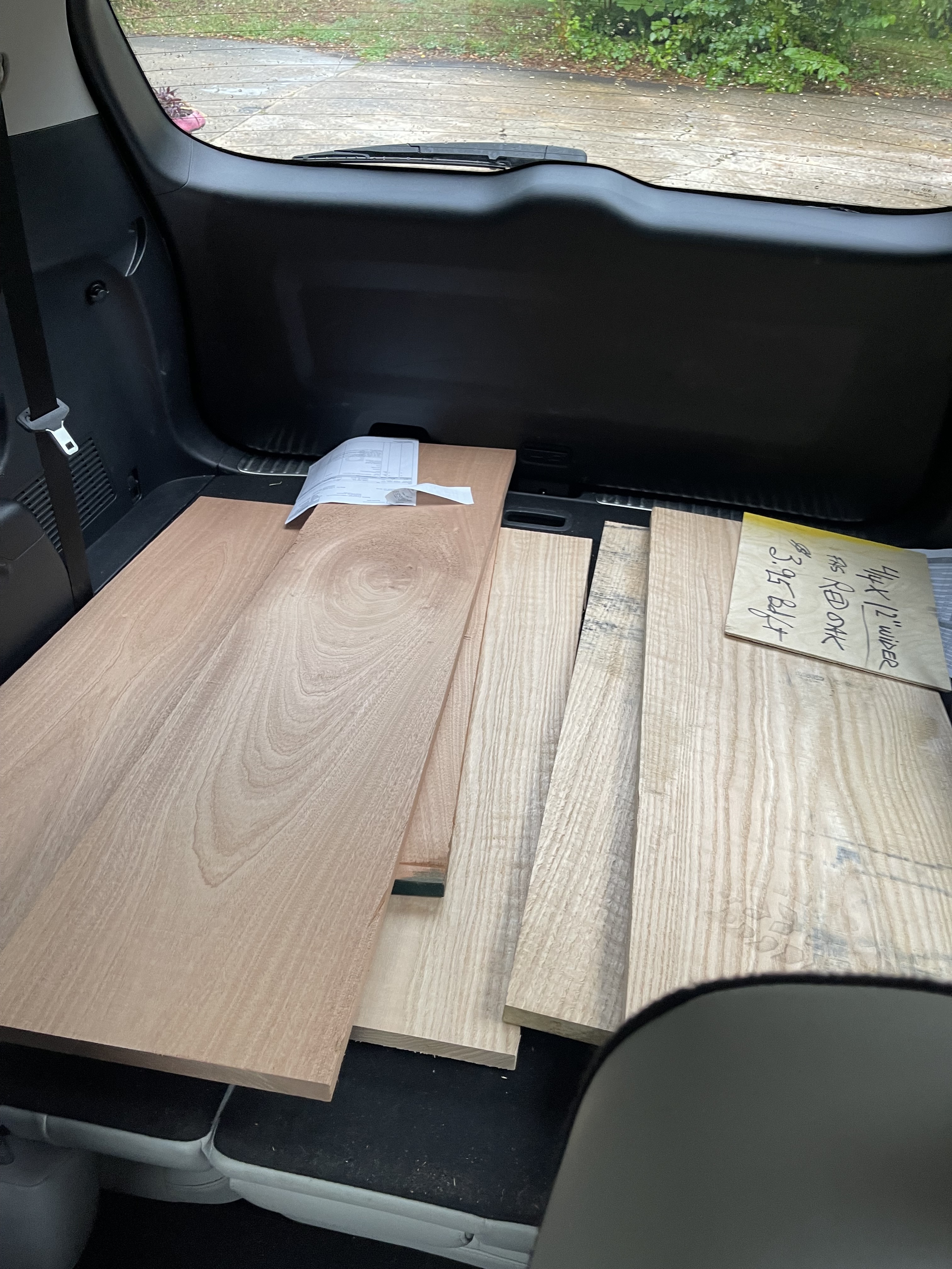
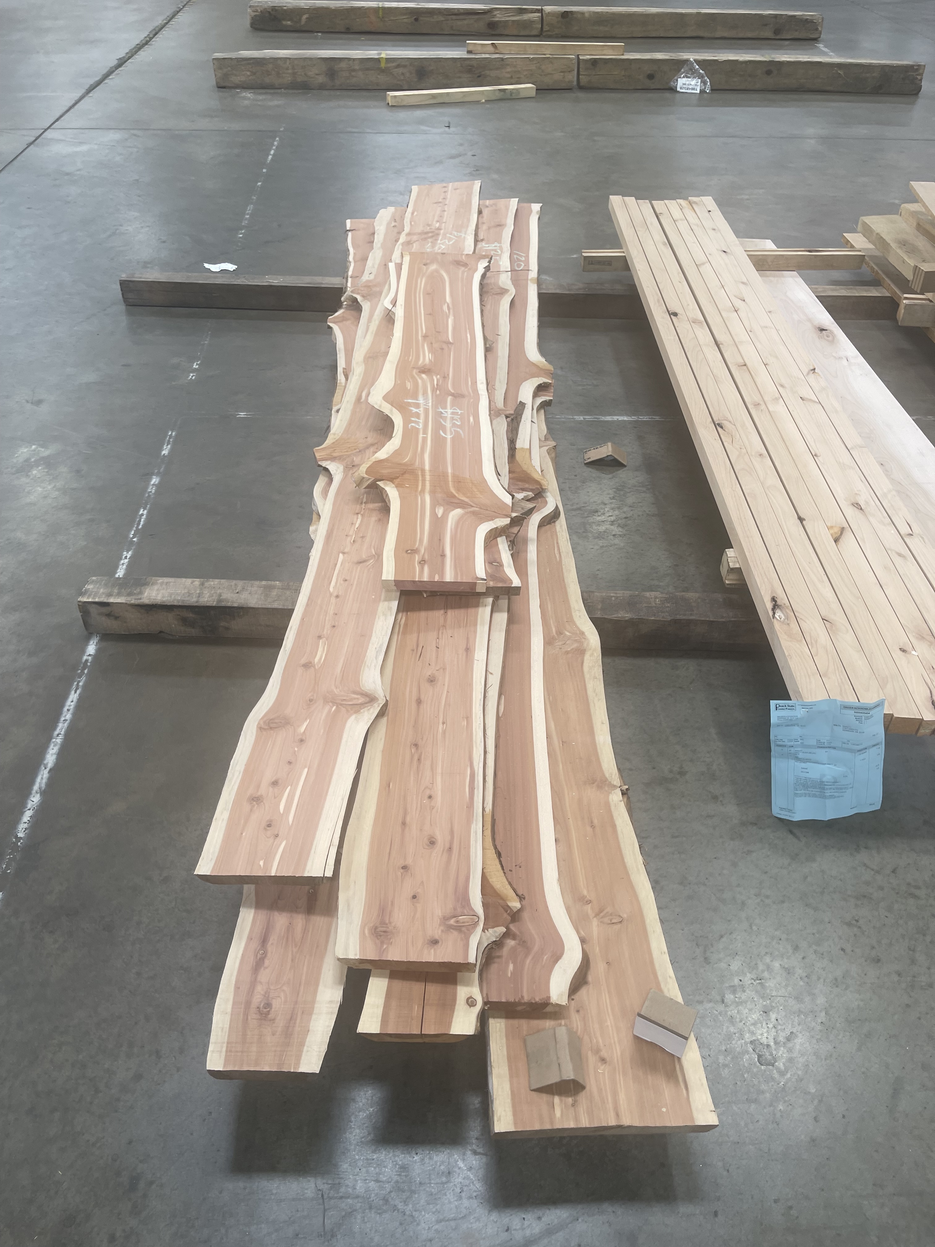
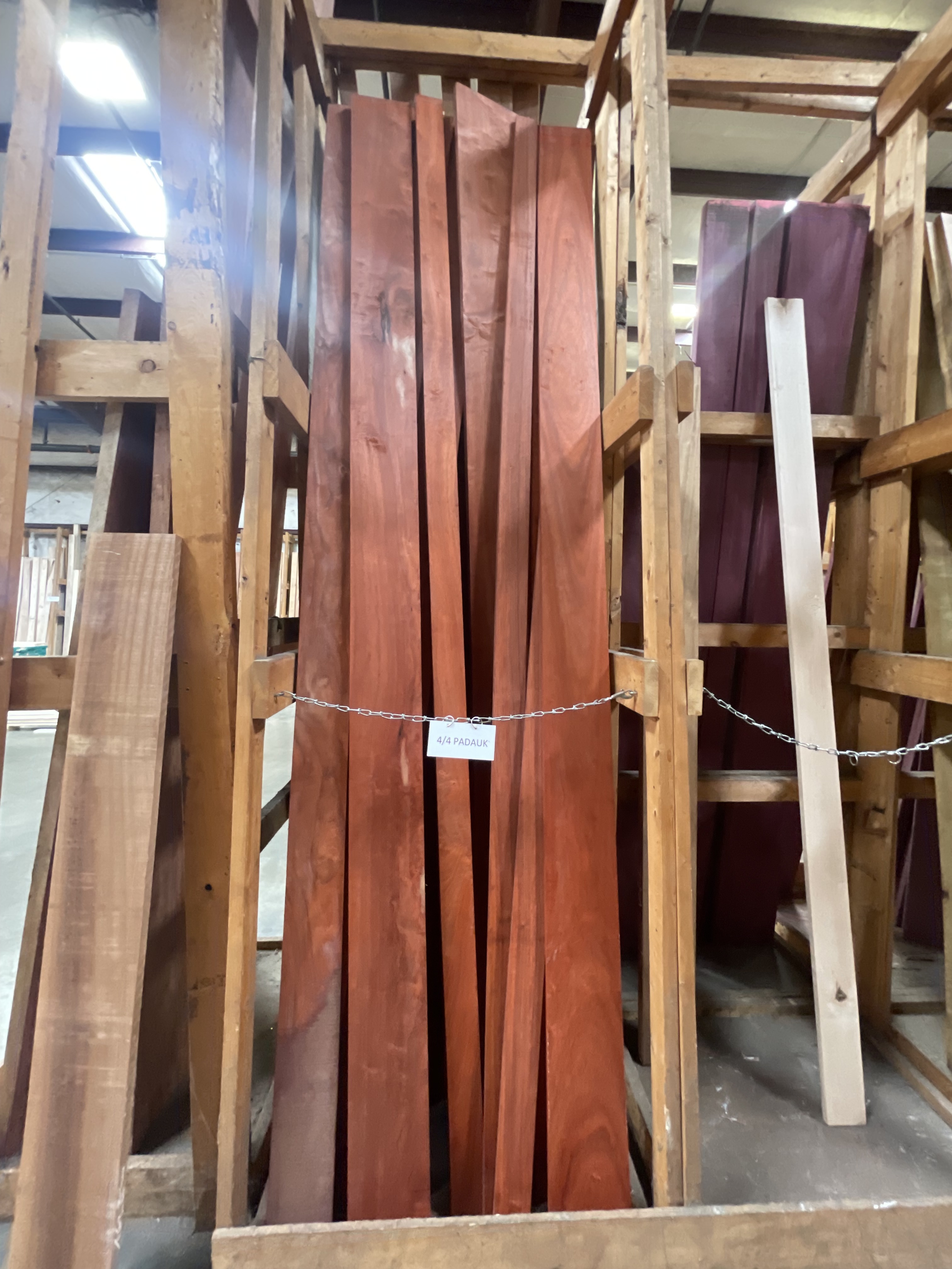
Update: wood has been acquired! Going with 3/4 in planks which I’ll plane down to 1/2 inch since I realized the side grain of plywood is well… plywood…
But I think these’ll look great! I got one half Sapele and one half Red Oak! I’m not sure how I want to finish them though since I’m totally clueless at woodworking so don’t hesitate to share any wisdom/ recommendations.