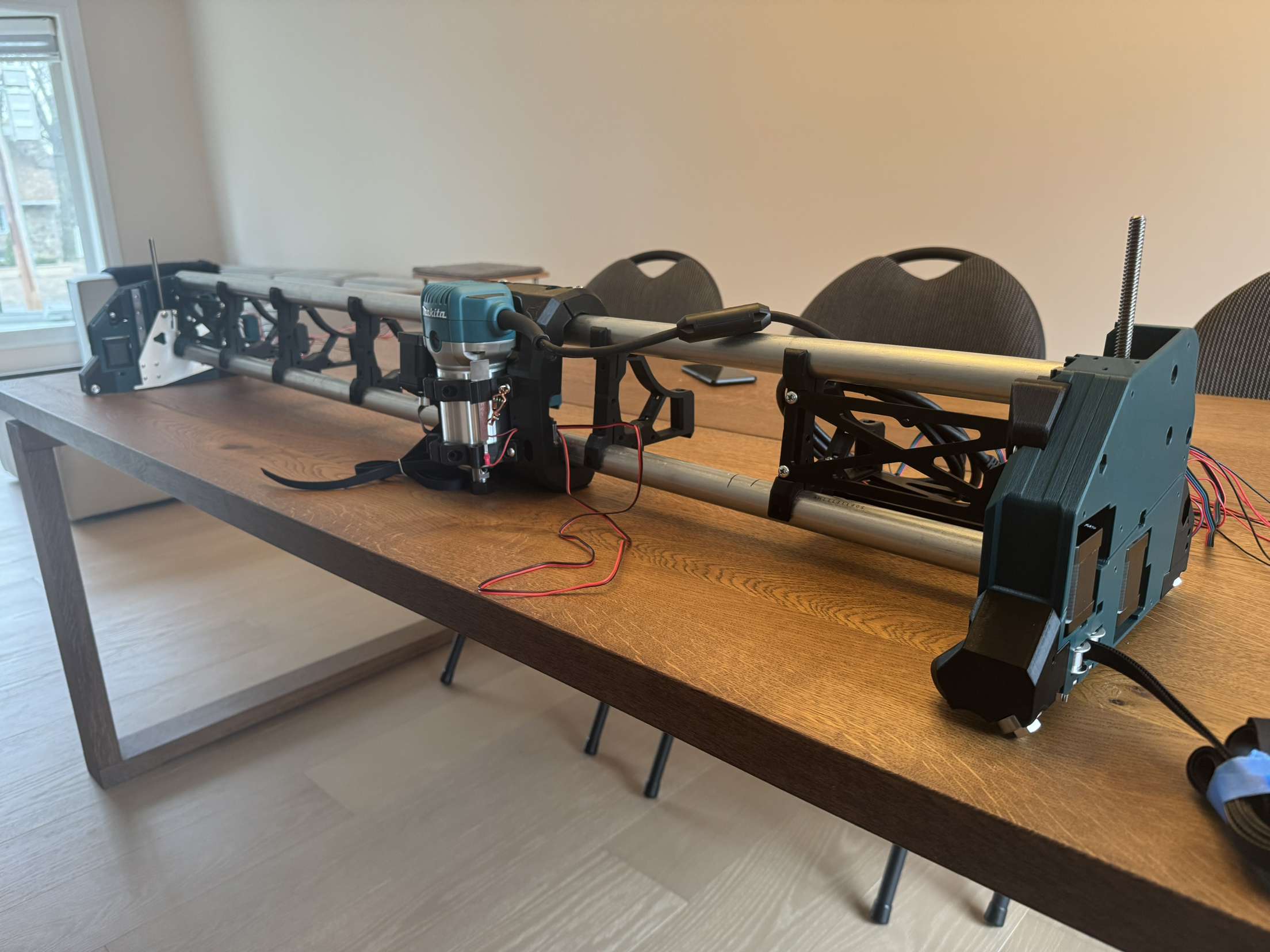
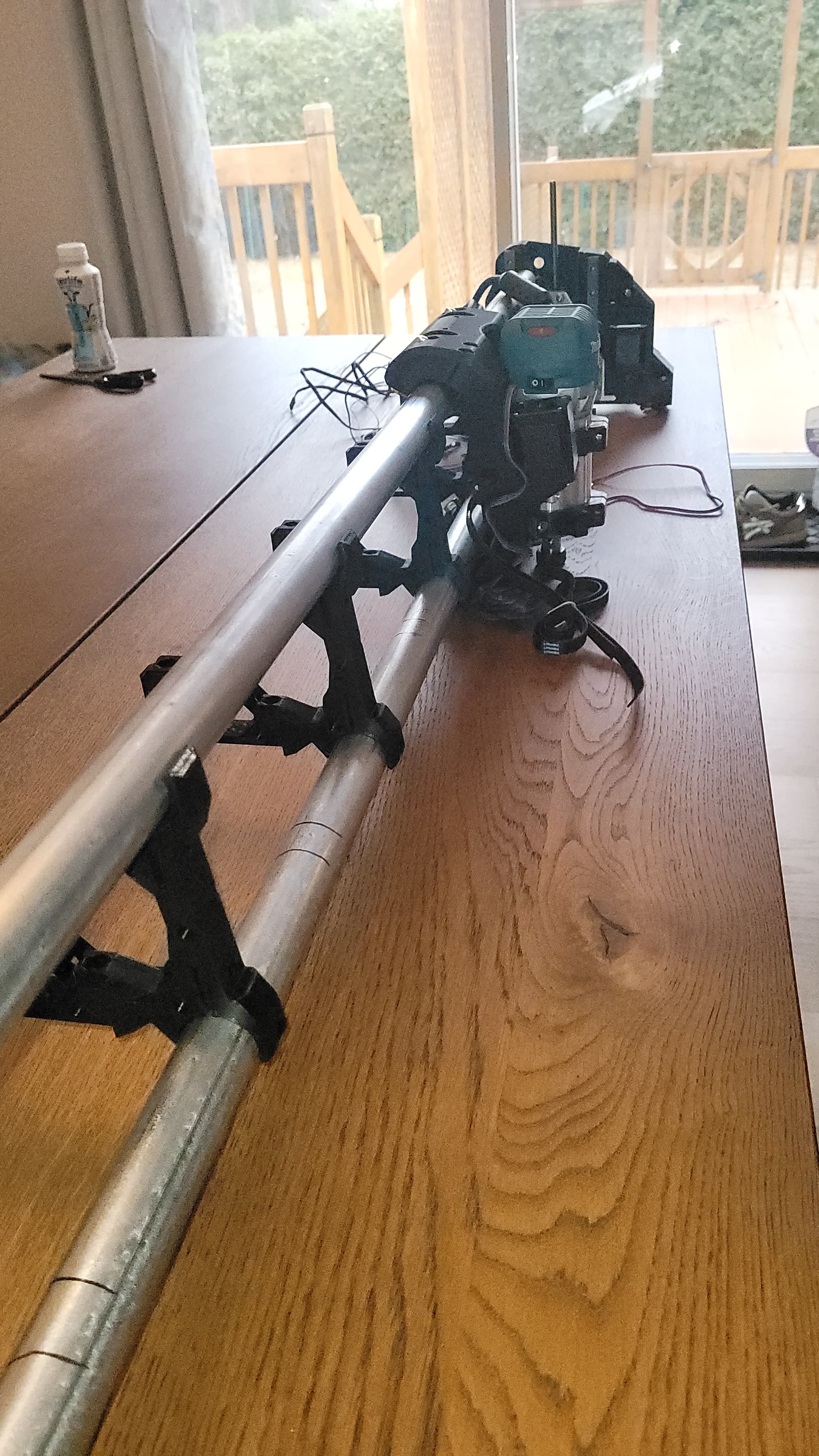
Had some spare time and space after moving and started up a lowrider build.
It’s gone great and today ended up testing all of the wiring with the control board.
Everything worked as intended except for 1 endstop. I recrimped and tried again but no go. No green light on the control board for Z1 endstop. I ordered some extra parts and will attempt to replace the endstop as well as the wiring but I wanted to know if in a scenario where I can’t get it fixed, it was advisable to potentially work with limits in the software? Would I be setting myself up for issues in the long run?
Thanks
3 Likes
Endstops just short across the two wires and should be set up as normally closed (shorted). Pressing on the switch, opens the connection. You can test your setup by carefully shorting and unshorting connections. You can start with the two pins on the board (wiring disconnected). You want to do this carefully to avoid shorting VCC to ground in the endstop pins on the board. Next you can test where the endstops plug into the harness. Finally, you can test at the endstop. Using this method, you can determine if the issue is the board, the wiring, or the switch.
When doing your testing, if the LED does not light when you directly short the pins, query the board about the endstop states in case the switch is working correctly and only the LED is the issue.
Software stops (soft stops) won’t work. The primary purpose of the endstops is to square your machine. You need individual hardware stops in order for the two motors to be assessed independently. In addition, the way most people use their machines, soft stops won’t work for setting maximum limits. You have to jump through some hoops with workspaces in order to have meaningful soft stops.