Build PLOG. MPCNC Primo, 24x30" area

I also use MKS Gen L and yes the lcd keys are backwards. I had to cut off the keys on the cables to fit them in backwards.

We now pause a moment while I get the wiring sorted in my head.

One thing that I’ve learned about my projects is that if I do something “that will work for now” intending to take it apart and make it better after it’s all working, it’s that I won’t. Not until something breaks. A prime example would be the wiring for the hotend on my 3D printer, which just failed expensively, because splitloom and a bungee cord to hold it up “will work for now.”

So, for the CNC wiring, I want to do it in a way that will work forever, or at least for the life of the machine.

The plan is to put a box just off the X0, Y0 corner of the machine, and have a drag cable go to the gantries. From the X gantry, a further tower will go to a drag chain out to the core for the Z motor and router power. The idea will be to keep all the wiring well away from anything sharp and spinny

Hey, Amazon parcel at the door!

1 Like

Yeah, I am really, really going to do the tape measure trick with my wires. Like, really! I only need something to fix them to the trucks/core. -_-

Cardboard and tape, man!

Bar clamp.zip (43.6 KB)

The .zip file has a clamp file that I designed that will fit into 1" .065 wall tube. There are 3 holes. The one in the middle will take a 3/4" #8 screw to force the sides open against the tube walls. There is an opening through which you can feed a wire harness, and 2 more holes spaced 1/2" apart (Also 1/2" above the center hole) I’ll be screwing 1" by 1/8" aluminum bar stock to this, and putting a little head on it to hold the drag chains.

1 Like


My first layer got gibbled, but this is it. The wiring kit fits perfectly in theough the gap, and if I tighten the screw it will probably support more force than the plastic. I might make a printed tower instead, it doesn’t need to be particularly high, and hopefully won’t need to be very strong.

I need to add wiring harnesses to my end stop switches with female Dupont connections on them. I twisted the wire onto the stop, but that’s not a good solution, really.

I need to look though the configuration.h file, but maybe someone knows offhand. I had everything connected, and then had a doubt. I connected ground and signal to the normally closed pins on the switch. For 3d printers, this is normally considered safest, using the internal pullup resistor. This way a disconnected switch reads as end reached. Well, it’ll cause trouble with dual endstop no matter how you do it if something gets disconnected I guess.

1 Like


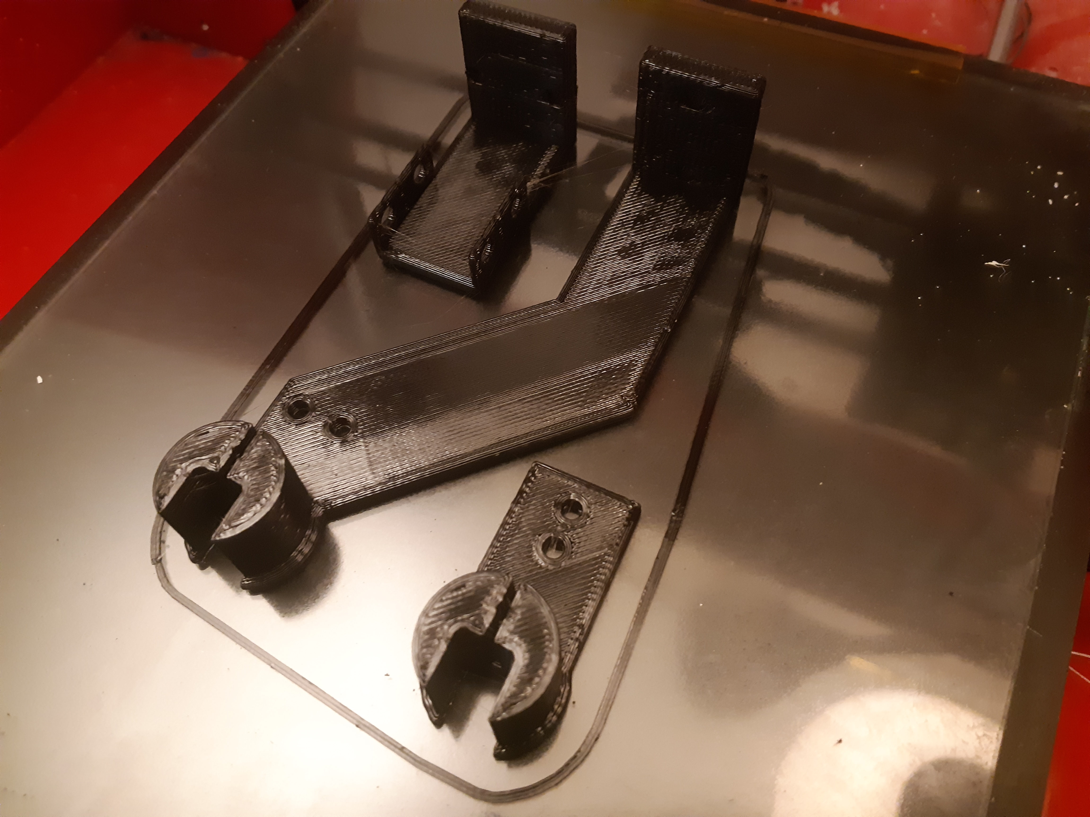
Freshly printed drag chain holders. Printed in PETg for strength and a.little flexibility. You might notice that the holes for the drag chains are oriented differently. I thought I had ordered identical drag chains, but on closer examination the X and Y drag chains are different and have the mounting holes set up differently. I can share the Mounts if people want, I suggest you modify them to suit yourselves


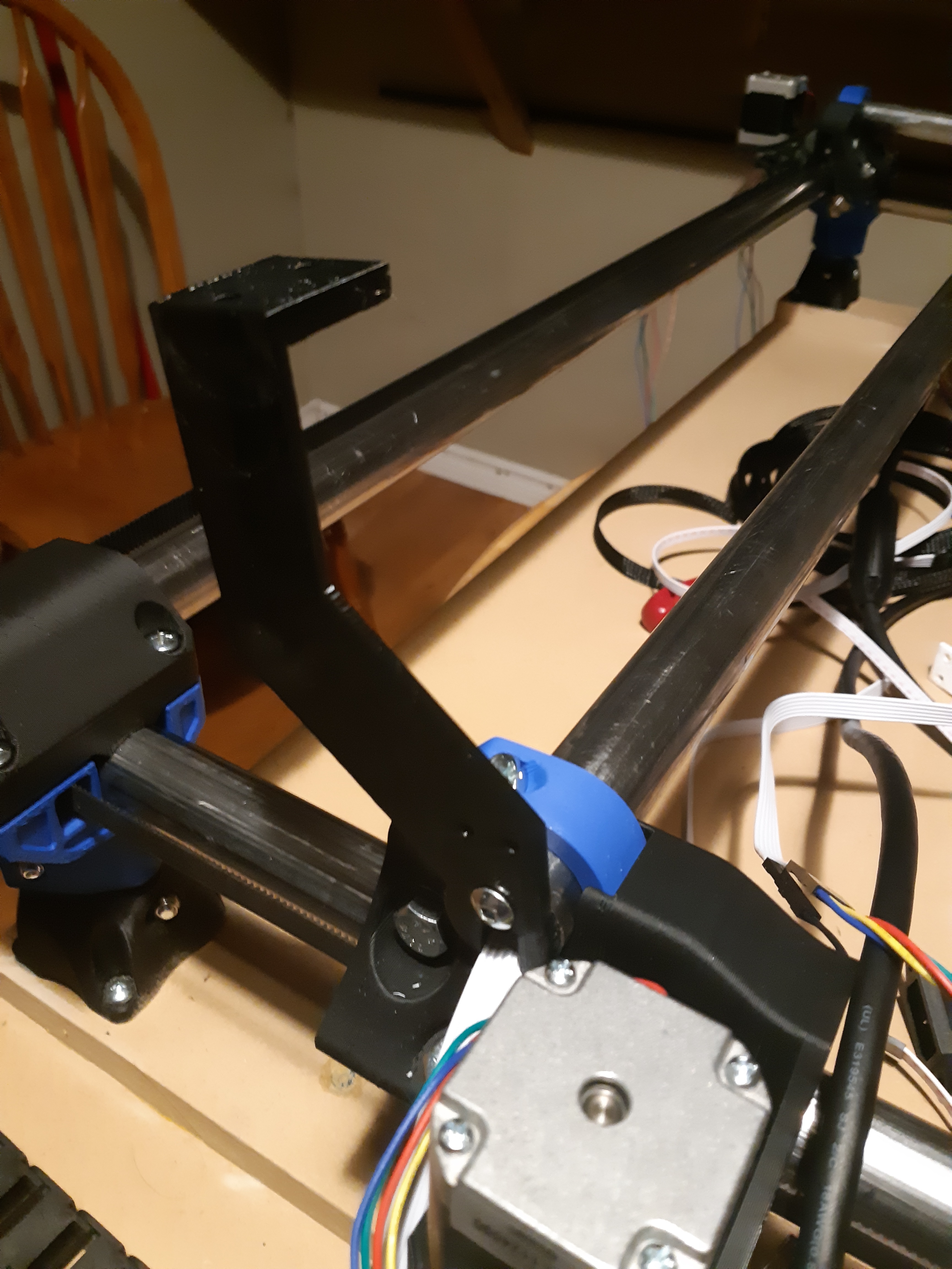
X gantry at the Y motor. This holds 2 chains, one to the control box and the one out to the core


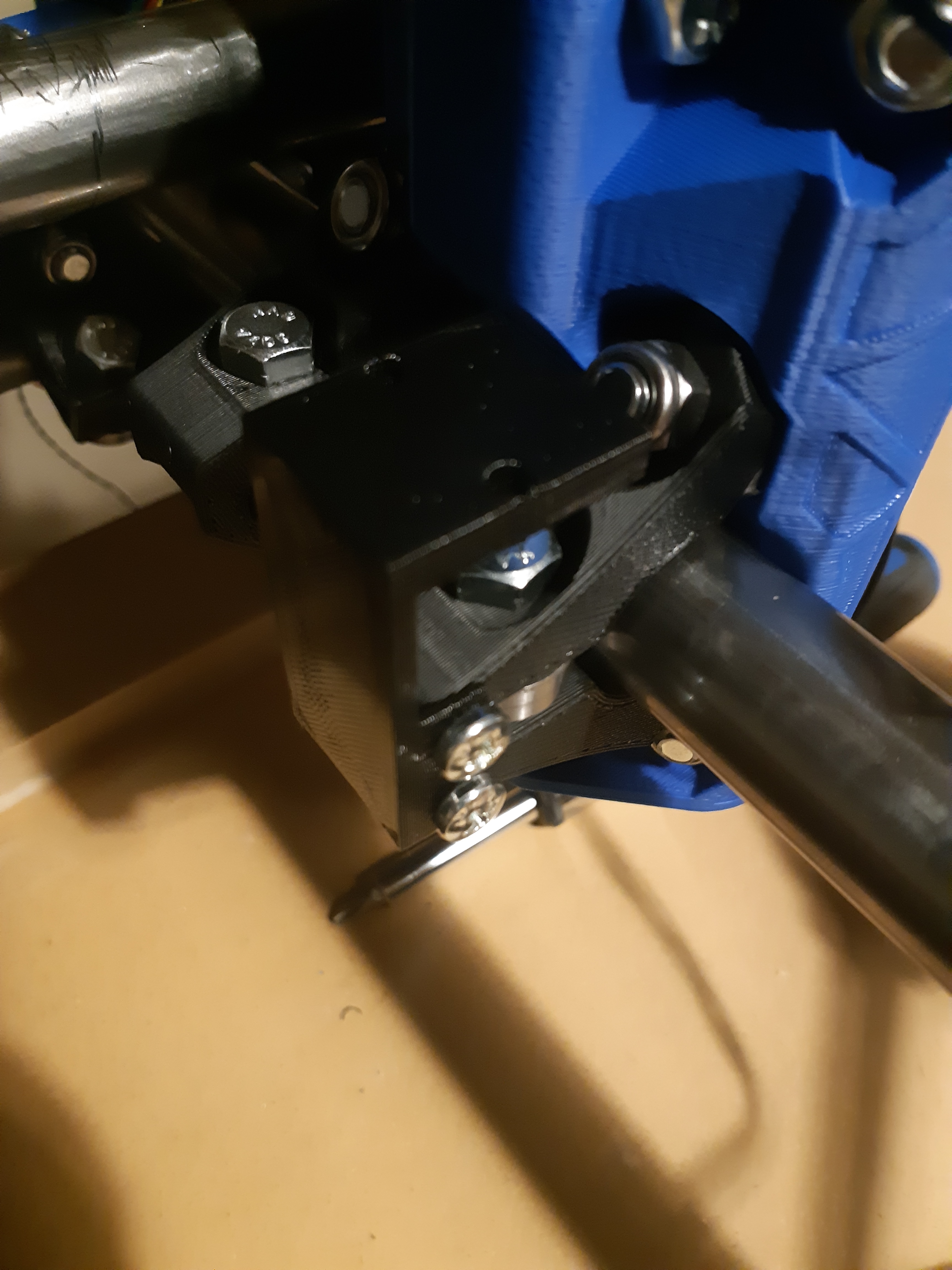
The core end bolts to the clamp at the provisions provided.


Y gantry at the X motor


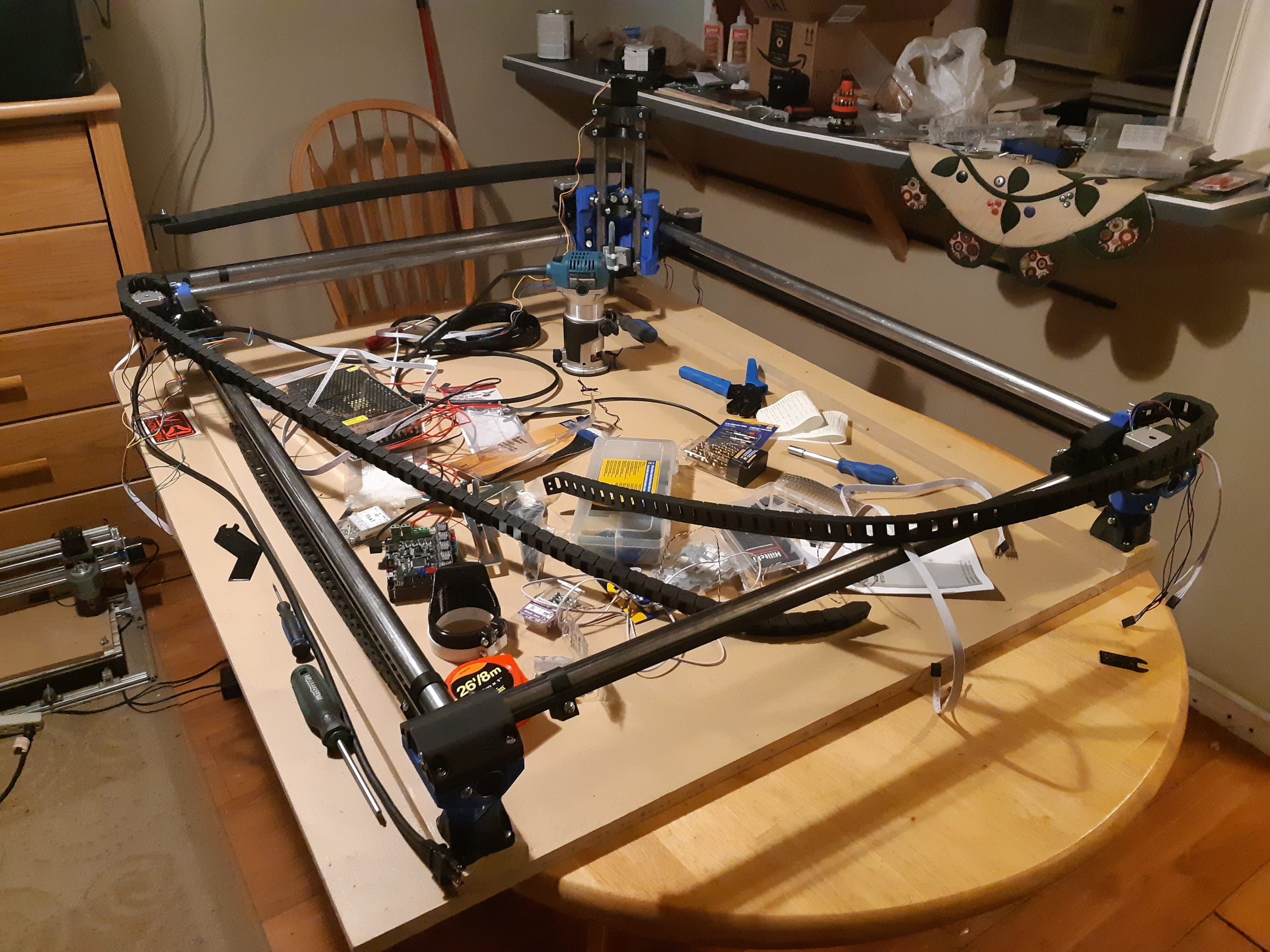
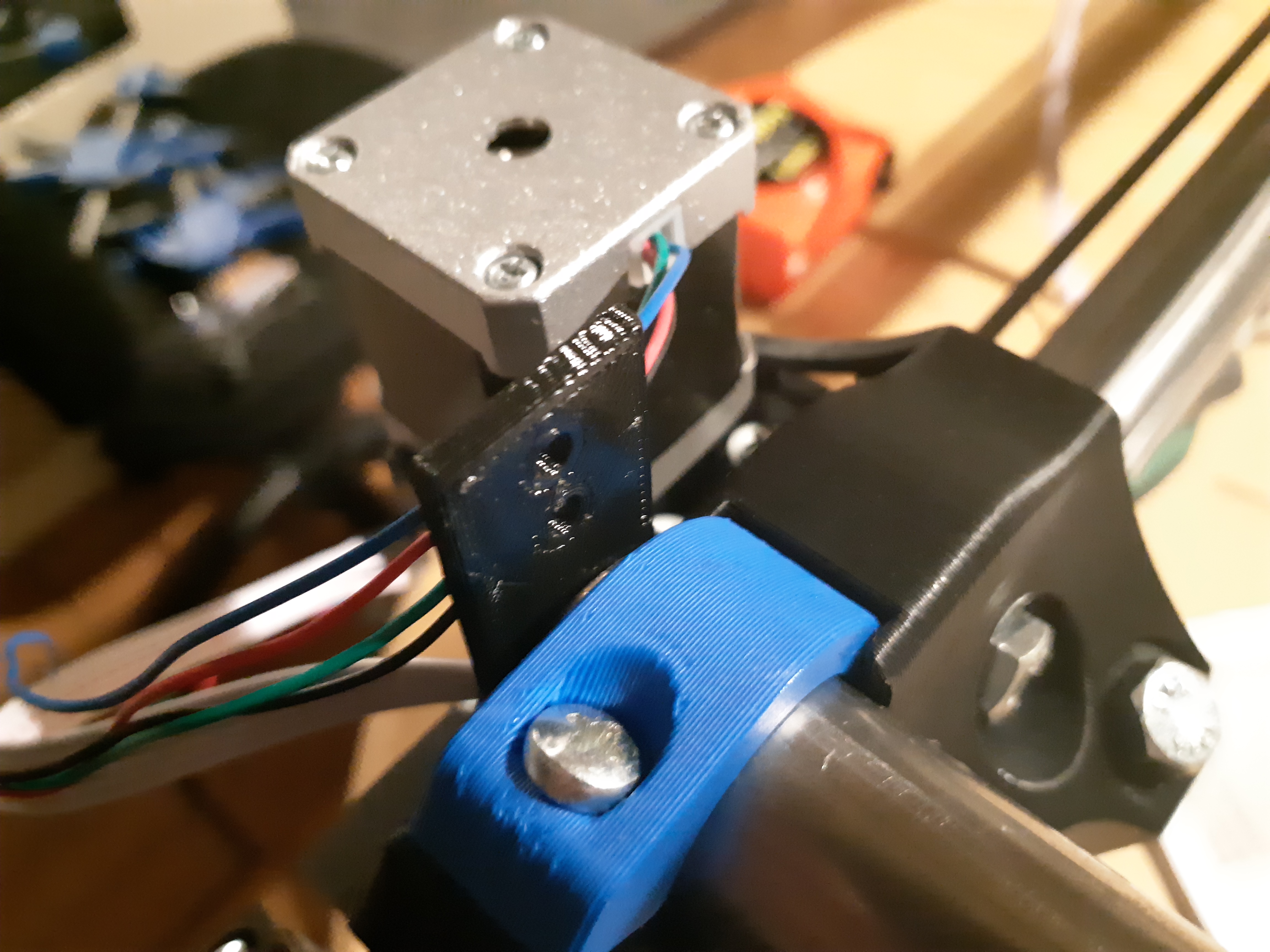
The work area getting cluttered again. Drag chains test fit. Nothing for the control box yet, and I need to extend the wires and attach cable to stop switches.

4 Likes


Well the wires are in place. I have a temporary 3d printed cap to anchor the drag chains. Not super pretty, but functional. Not so functional that I won’t fix it, but the fix is some cut material, so I need it working first. Chicken and egg problem.


And very first test job, running the 22mm/s crown code. I really want to make some chips, but it’s 02:40 and power tools and being this tired not a good mix. Just finished working and needed a motion test.

YouTube video of test crown

I forgot to check the end stops… they are wired to the NC pins on the switches, signal and ground. I think that jives with what I saw in the Marlin configuration.h file.

Check stops and then chips tomorrow, if I get some CAM done.

6 Likes


My first CAM and cut.

It’s the logo for my kendo club, which will probably be on more than a couple of cuts for this thing at some point. Might as well start now.

The Makita mounted nicely, and the 1/8" to 1/4" collet adapter didn’t seem to give any issues. This was at 1mm DOC, 8mm/s speed, using the 1/8" single flute I bought with my printed parts. I’m sure I could have gone faster, but I thought it was a conservative safe start.

6 Likes

Two steps forward


Started working on the pieces to constrain the drag chains and hold the electronics steady. This corner tower anchors the drag chains, and holds a piece of slotted angle at the front end. Currently the job at the back end is a couple of clamps.

One step back.

The MKS Gen L board fell, and now the Z axis won’t move. 4/5 motor drives seem okay, but the Z axis sounds like it’s stuck and moves down whether commanded to move up or down. I think I saw arcing at the board connector, so the board or Z driver (or motor) may be damaged. It needs diagnosis, at the very least.

Before that, I was cutting MDF at 15mm/s with a 1.9mm DOC and got those 2 panels with a very nice finish. A touch of sandpaper to remove the hold tabs and fit the power socket and router switch. Screwed to the table and attach the drag chains. I was going to mount the electronics, there is a provision for the Gen L mount, and my V1pi (not currently connected) drilled into the MDF side.

I still need to add mid-span support to the Y axis rails, and support the slotted angle for the X axis drag chain…

But first, diagnose what I screwed up on the Z axis… Oops.

1 Like


2 more steps forward.

So, hoping that it was a problem with my crimp, I cut the connector for the Z motor off and put a new one on. Problem solved. When I took apart the failed connector, it wasnt the crimp after all, the pin socket itself got pushed too far open and wasn’t making good contact with the pin. Never seen that before.


Mounted the electronics. No more falling. AC power isn’t connected to the socket and the router switch isnt active. The DC supply and router are plugged into a power bar under the table still. I still have to hit the power switch on the tool. Cutting the rear support for the slotted rail, I bumped the router down, and instead of starting 1mm over the work, it was touching. Not the end of the world for a piece like this, but it will be nice to have that switch.

I broke my first bit. Broke the collet adapter, too. The router picked up the work from the table and that was it. Fortunately the adapters come in sets, but that was my nice single flute. The double gets hotter, scorches a little in the 4mm holes.

3 Likes


Wiring complete. Well, power is. AC power now all comes from the IEC socket. The master switch there turns on the main PSU, and one outlet at the back of the machine, and supplies power to the safety switch at the panel. The safety switch turns on power to another outlet, which is where the router plugs in. Everything is grounded properly.

I still need to bolt down the DC supply, and shield the electronics from dust and debris. Then a dust shoe…

1 Like

Today was getting the machine dirty in kind of a boring way, but kind of cool. Cutting spoilboard. I had the machine cut 24 holes in a grid, 6 by 4 into a piece of 5/8" MDF. There is a 20mm pocket, cut 2mm deep, and then an 8mm hole in the centre cut through. These hold 1/4" - 20 T nuts. There will be a total of 4 of these to cover the whole bed area. Not 100% sure that making the spoilboard in 4 parts is the best plan, but that’s about the only way that I could cut a reasonable grid into it, unless I wanted to do it by hand, and I really didn’t. The spoilboard will be 4 sections, each is 400mm by 600mm. It just happened that 800mm is the space between the 2 stringers that my CNC sits on. Wasn’t by planning, but that’s how it worked. I cut a jig on the tablesaw to hold the board in place so that one corner is exactly under the home position on the CNC, so I can just home the machine and start, and I’ll get 4 identical boards.

Slow. The helical drill pattern for the 20mm pockets takes a very long time. By comparison the 8mm through holes go very fast. I thought that I had a 1/4" straight bit for my plunge router, but when I looked, I could only find a trim bit and a 1/8" that wasn’t deep enough (1/2" cut depth)

I cut the first piece only tonight. I’m using a 1/8" Amazon sourced single flute. The first couple holes were… rough. the edges were rough, it smelled half burnt, I thought I was going to have to slow down the cut speed, but by the 4th hole things smoothed out. Just regular MDF dust smell, and the edges looked good. Almost like the bit needed to be broken in. By the end of the job, I thought I could have gone deeper and faster. Usually these things seem to go the other way, getting dull faster than I expected. Right now, I kind of like this bit. It’s not as nice as the V1 bit that I broke, but ok.

I might go buy a 1/4" straight bit though, then I won’t need to pocket the 20mm cut, if there’s an 8mm concentric, I can just tell Estlcam to cut a hole, I bet it’ll go WAY faster.

1 Like

Home Despot doesn’t have a straight 1/4" bit. 5/16", 3/8", 1/2", 3/4" and 1", no problem. For quarter inch only trim bits with the bearing on the end in various lengths, and I already own 2 of those so… No dice.

The Amazon bits worked okay with the settings I had, but speeding up was a mistake. Test cuts in 1/2" MDF resulted in a scorched and overheated bit, so back to the same speed, and did the second spoilboard today.

My CAD skills are improving. I got my first successful STL from FreeCAD. It’s similar to the shape in the constraints tutorial, but with a hole for a 7/16" wrench nut for the 1/4-20 thread that I have the T nuts installed in the spoilboard for. It printed a little funny. Slic3r doesn’t seem to like the circles that FreeCAD draws, and the printer kind of stutters on the curves, running up against the jerk settings, so it printed slow, but I have a half dozen nice thumbwheels, or I will once I glue the nuts in. I gave them the usual 0.15mm clearance, and the nuts dropped in with about 0.15mm clearance. Weird. Well, I’m coming to understand FreeCAD a little. Just as I was getting used to Fusion360, they went and changed the license, so maybe I won’t be using it so much after all. TinkerCAD actually works quite well for me, I’ve done projects WAY beyond the scope of what TinkerCAD should probably be used for with it, so it’s time to move on and learn a little. Fusion360 seemed like a logical move… FreeCAD has some frustrating things about it, like seriously unhelpful error messages, and a slightly warped workflow, but I’m getting used to it. Maybe Fusion360’s free version becoming crippleware will light a fire under the dev’s coccycx and FreeCAD will see some improvements.

I was going to cut the last slotted angle brackets for the drag chains, but the test cut ruined my piece of MDF that I was going to use for it. I might have more in the garage, or I might have to re-do the CAM work to replace it with 5/8" I’ll look in the morning.


New holder. Finally got to remove the clamps holding up the slotted angle for the front drag chain. I.still have to finish the spoilboard, but there is enough of it there to do some smaller jobs now.


The other side. I had an inspired moment, and put a line in the CAD drawing in the shape of an L, and told Estlcam to engrave it a quarter inch deep, then just set the angle in it. A hole above and below hold a zip tie to make.sure it doesnt fall out. There’s a.nut and bolt at the other end.

2 Likes


Another test. Big pocket, but not deep.

I don’t know how I missed it, but the machine has a big wobble in it. Under load the whole core rolls.along the Y axis, so the bit pulls from plumb off towards X min. It makes the bottom of the pocket kind of sloppy. I think the finishing pass was enough to restore the detail, because the inside of the circle looks okay.

I think this means I have to tighten something, but I’m unsure what.

Edit: found it. One of the core clamps on the X rail was loose. The ones we are cautioned shouldn’t need any extra tension. Looks like mine loosened from the cuts I’ve made.

2 Likes

Did you plug in your driver all the way?
Check this image 20200929_233909

Yeah, I saw that the drivers had been pushed a bit when I did the electrical. Snapped those before I turned it on. I did fix that before turning it on, the E1 and X drivers both had been pushed out, and I had to replace the adhesive on the X driver heatsink. Should have left more room. I also plugged the 5v power wires to the Pi all the way in, too. Just in case anyone was wondering. :laughing::rofl:


Today’s MPCNC project wasnt spectacular, but maybe important. A DIY touchplate. Some 2 pin cable with a 3 pin Dupont connector, to plug into the endstop connector.

A small alligator clip on the ground wire and part of an aluminum cable tie on the signal pin. The flat part had 3M foam tape on one side, which I removed. I don’t know it’s exactly 0.5mm, but it’s really close. I think it will substitute for the V1 version.

Edit: Okay… Good thing I put that heat shrink on there… Turns out that if I’m touching the aluminum at all, it reads as triggered, even if I’m not touching anything else. The aluminum is softer than stainless so I have to be careful how I press it to the work to home Z. Other than that, and not having a place to hang it when not in use… Works great.

Using the Home Z function sets the contact point as 0, and not 0.5, but that’s workable. Most times, I’m not going to miss a half mm anyway, though I might for some projects, so I’ll have to fix it.

Well, the aluminum touch plate seemed like a good idea at the time. The problem is that it doesn’t flex, it just bends. So if you can hold it down flat enough, it works great. Usually though there’s some uncertainty as to the height above the work that it homes to.

Working on the 2.5D LCD case next. Bought some poplar for first run, but hoping to manage some red oak.

Sounds like you need a 20K to 40K pullup resistor between S and +. Common boards use an internal pullup resistor, but if it is not functioning…

Using the Home Z function sets the contact point as 0, and not 0.5, but that’s workable. Most times, I’m not going to miss a half mm anyway, though I might for some projects, so I’ll have to fix it.

If you are using Ryan’s firmware from his GitHub page, then there should be a custom menu. You can modify that menu to take the the 0.5 into account. Search for CUSTOM_USER_MENUS in Configuration_Adv.h.

As an alternate, I saw one person on the forum put a bit of code in a .gcode file and executes it to home Z
G28 Z
G92 Z0.5
G0 Z5 F480

1 Like