Build in Wisconsin coming together

I’ve been posting bits in other sections, but realized I hadn’t started a “My Build” thread, so here it goes.

Initial planned use is wood working and cutting out foam aircraft for R/C. We’ll see where it takes us one those use cases are nailed down. Inlays look very intriguing, expect I’ll be trying them pretty quickly.

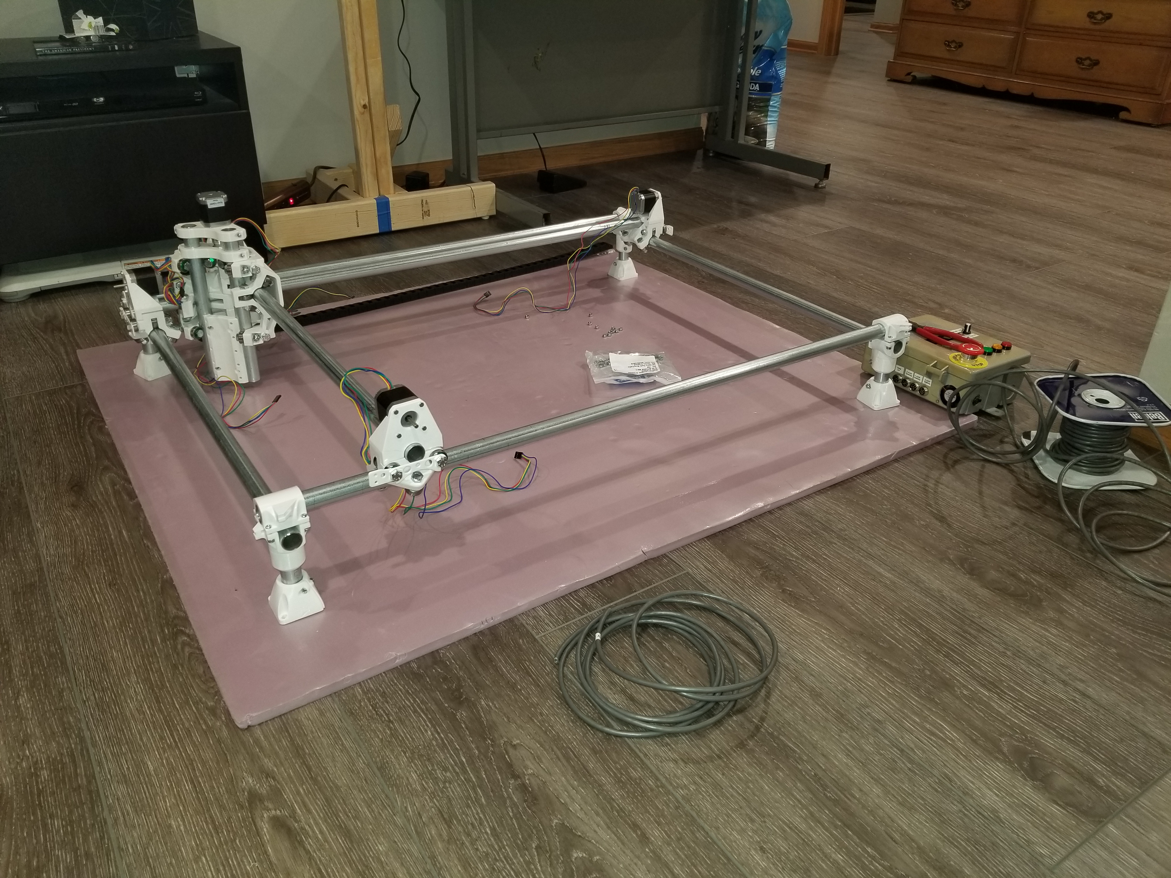
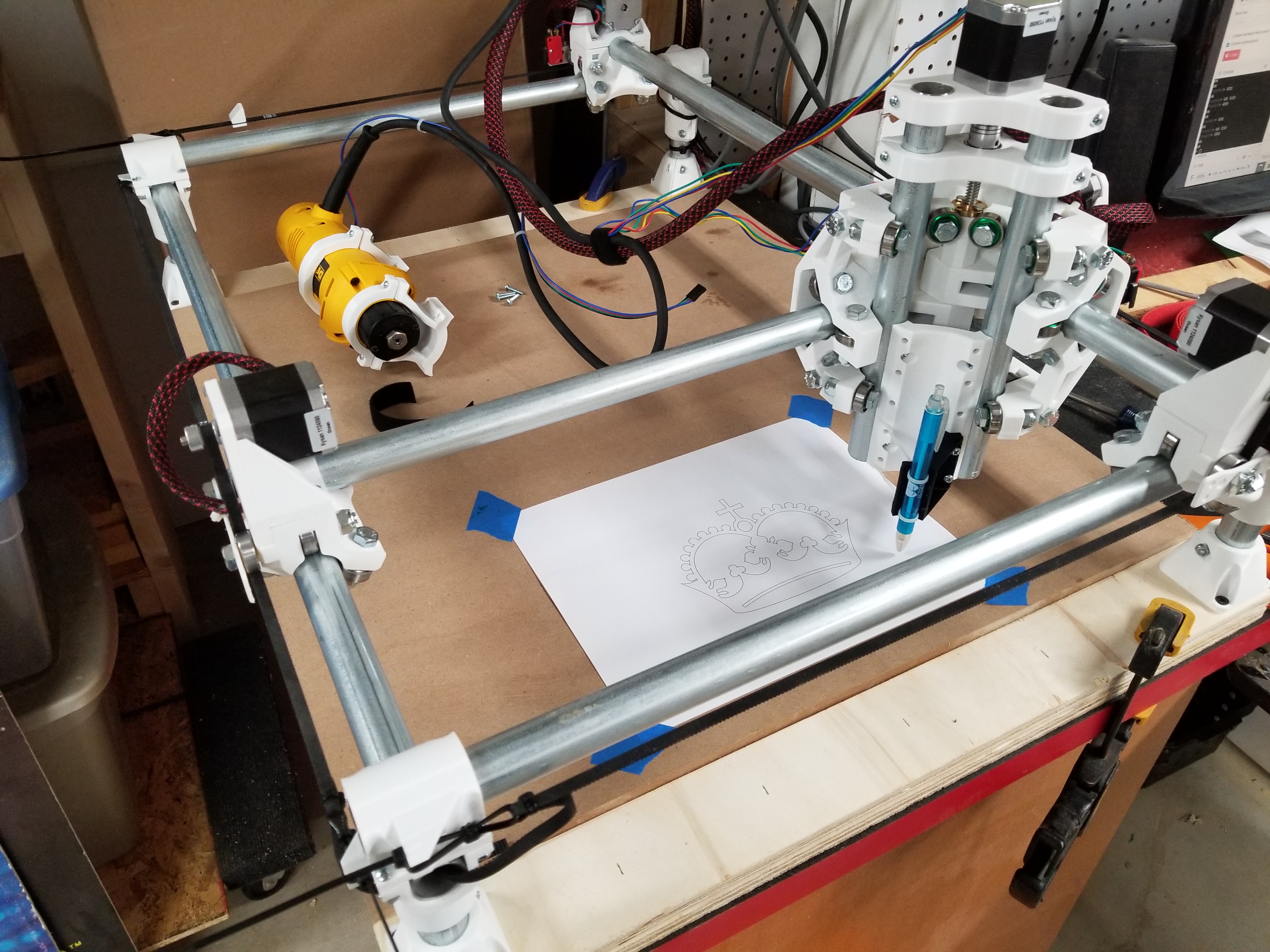
US build, so imperial units, at least until I get to gcode. Planned working area is 21"x31" (full sheet of dollar tree foam board plus a little wiggle room) with a 3" Z, using 3/4 conduit. Rails and legs are all cut, printed part sub-assemblies are all together and the bearings seem to fit around the tubes correctly. I put the assembly on hold while I think through table options. Probably going to want a folding/rolling table, as shop space is not unlimited. For the spoil board, I’m thinking removeable/flippable spoil board with one flat side for vacuum hold-down of the foam and dovetail slots routed in the other for flexible work clamping over a “drop table” to allow room for taller work pieces.

For controls, I’m using a CNC Shield 3.0 clone/Arduino Uno combo that’s been on my shelf for a while. I used the same hardware to replace the brains in my K40 laser, so I’m comfortable with the platform. This will work with GRBL 1.1, but you need to understand that the silkscreen on the board doesn’t match what some of the pins do any more because the had to shift pins to get PWM working.

I’ve got the PWM “developer kit” from the V1 store for spindle speed control and I’ve added a switch to allow manual speed control via a 10K potentiometer, There’s also a 4-channel relay board (also been on the shelf for a while) and a buck converter to lower the 7 amp 19V DC from a laptop power supply that feeds the steppers to 12 V for a case fan and possible LED’s at the bottom of the Z axis.

I’ve got the V1Pi image up and running, so with CNC.js operational I’m not worried about not having a graphical control UI on the machine itself. The GRBL shield provides for Cycle Start, Pause, and Cancel buttons so I’ve got illuminated buttons for them on my control box. The normally-closed side of the big E-Stop will kill all AC power into the box, stopping all relay controlled accessories as well as the outlet the laptop supply plugs into. The GRBL board also supports an E-Stop to reset the controller, so if tests after assembly show it doesn’t stop fast enough, I may hook the normally open side of the E-Stop to those pins as well since the arduino is still powered through USB even when all AC power is cut off.

I’ve been concentrating the last couple of days on getting the “brain box” put together and wired up. As of last night, almost everything was operational in a bench test via CNC.js

  • GRBL start, pause, cancel buttons worked
  • X-Y-Z motors turned
  • M3 turned on a desk lamp plugged into the spindle outlet
  • Changing the RPM dimmed the bulb
  • The PWM cutover switch and pot also dimmed the bulb
  • Relay lights responded to M7, M8, and M9

Just need to crimp some more connectors to get the LCD wired in and add the sensor wiring to hook up the spindle for a test run.

Here’s a couple of pictures of the controls, shoehorned into an old outdoor electrical control enclosure that’s also been kicking around the shop for a while. (Anyone else sensing a theme?)


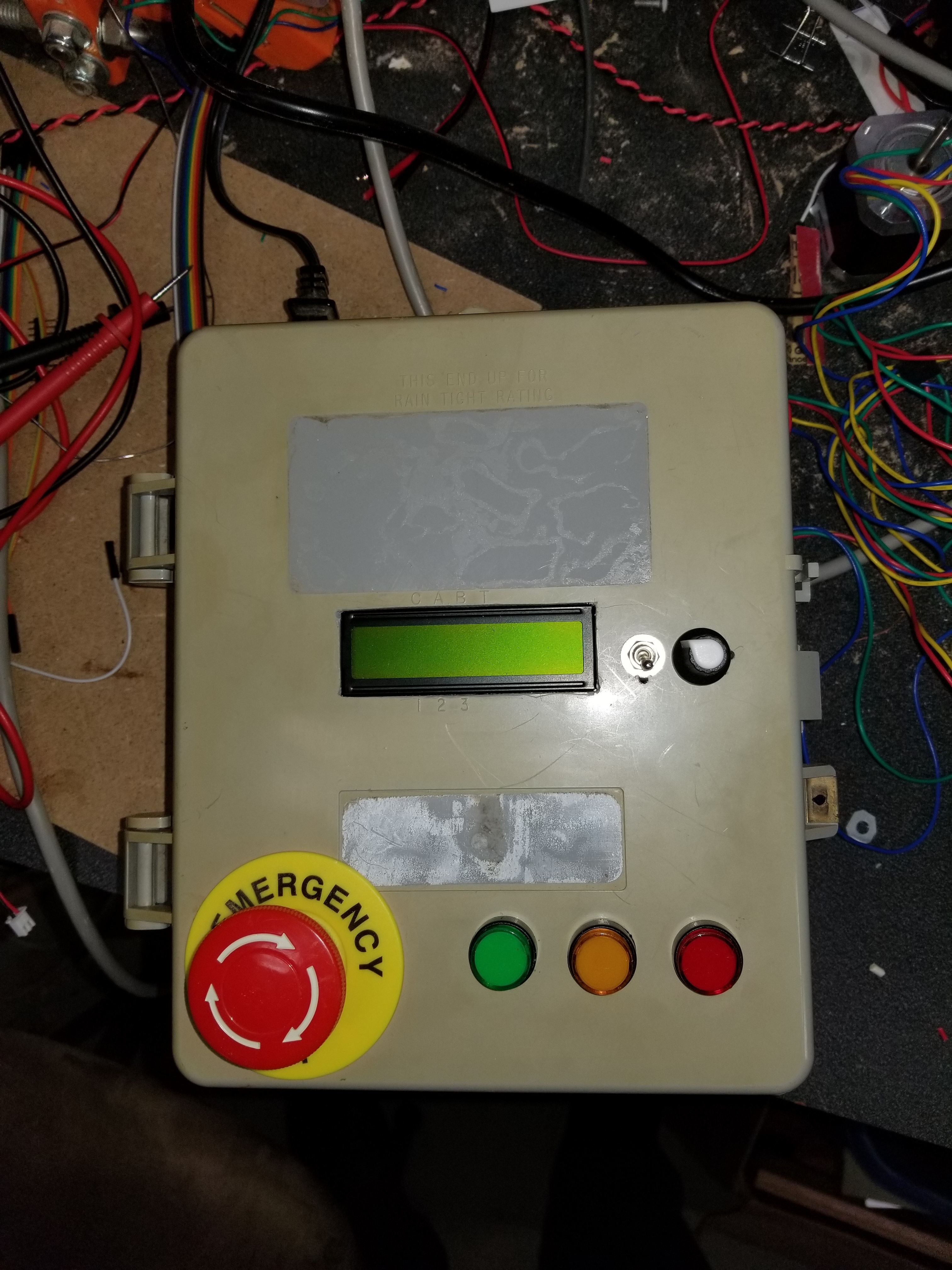
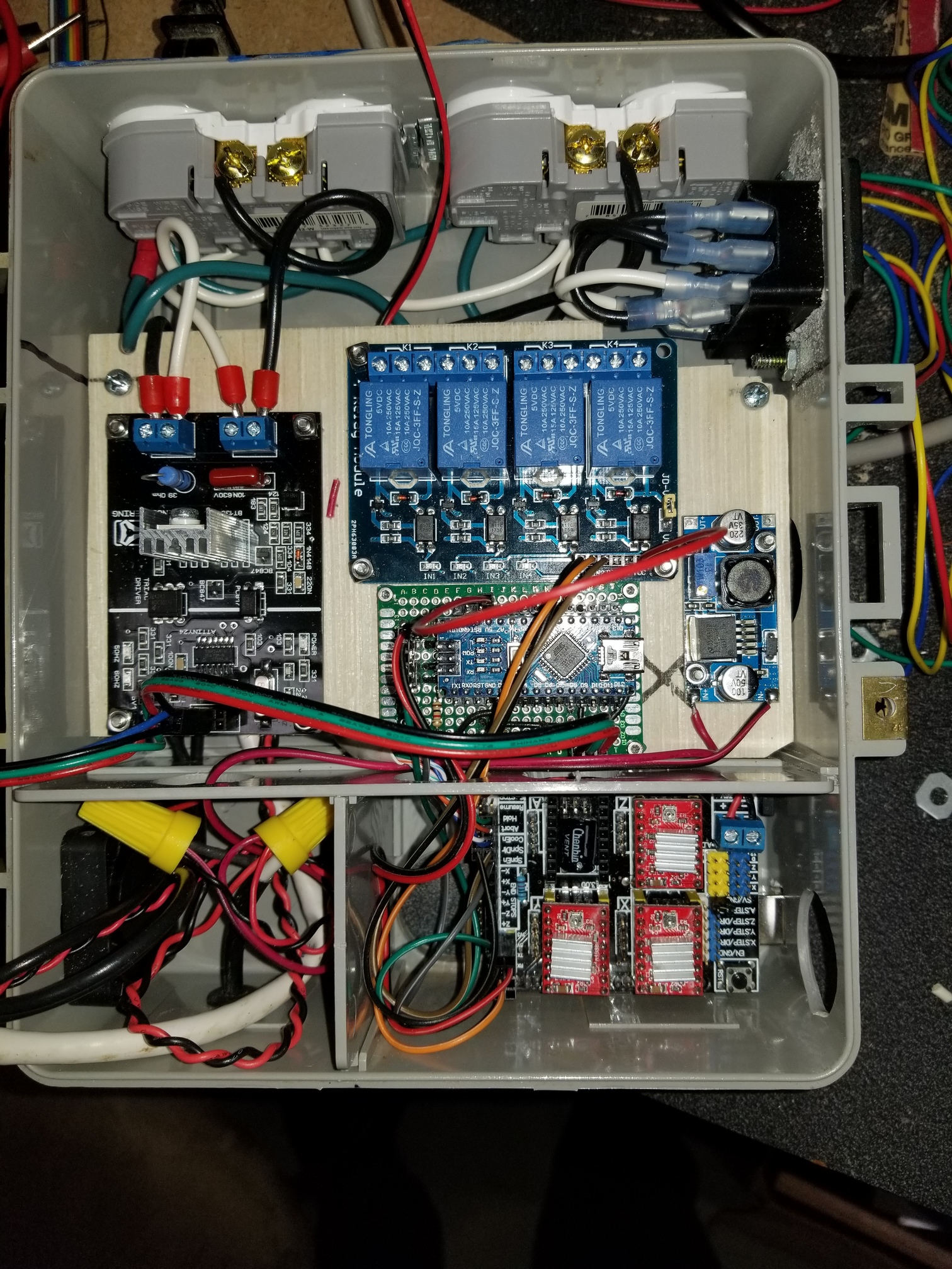
Steppers, limit switches, and RPM probe wires will feed through the left side of the box using some 6-conductor cabling that should make setting up modular wiring runs pretty easy.That’s a standard IEC fused power inlet on the right side, so I don’t need to use the E-stop as the main power switch. I will be putting protective coverings over the hot leads for the outlets along the top once the relay wiring is complete, and getting some slightly more elegant DC power connectors to replace the yellow wire nuts. Most of the power wiring runs beneath the plywood that the circuit boards are mounted to.

Now to figure out the table so I can get the whole machine put together.

5 Likes

You say that so nonchalantly… I’ve literally tried to restart my build at least four times before the frustration of the connector crimp caused me to ragequit. And I keep getting PTSD twitches every time I pass the basement door (where the in-progress carcass lays in wait).

Apologies to anyone who actually suffers from PTSD, I really don’t mean to make light of your trauma or suffering.

I had been putting off some of the wiring because I knew there would be a bunch of crimping, but last night I realized I had stranded breadboard jumper wires that already had ends crimped on them. I’d bought a collection that included male-male, male-female, and female-female so not only did they have ends, I had a rainbow of colors from which to choose. For many of the connections last night I just took off the single outer plastic end and slid the jumpers into the right slot in the bigger connector “jackets” from my dupont kit. I only had to crimp maybe half a dozen metal ends myself.

Unfortunately the LCD is about an inch and a half too far away for the jumpers I’ve got, so I’ll actually have to strip and crimp those.

I’ll probably do my motor serial harness at the same time once I’m “in the zone.”

Those have been hit or mids with me. Definitely useful (and the guy with the swedish accent on YT recommends them). But some have made me crazy because they should be connected, but inside the insulation had literally rusted through the wire.

I should record my method for crimping dupont. It is a bit of a pain, but it isn’t keeping me up at night.

My crimping method (given that I’m using an el-cheapo non-ratcheting crimping tool):

  1. Strip wire end
  2. Twist wire end
  3. Trim wire end (I always strip more than is needed for some reason, should probably invest in better strippers)
  4. Put wire in crimp end and use needle-nose pliers to squeeze crimp around insulation just enough so it doesn’t fall off when I put it in the crimping tool
  5. Line up in crimping too. Contortions required if I forget to turn the wire in the magic right direction which always feels backwards when I’m doing it.
  6. Crimp
  7. Examine crimp to make sure insulation is held and bare wire is crimped. Multi-meter continuity test if I’m worried.
  8. Trim excess wire at connector end of crimp. Yes, even though I trimmed it before I end up with too much poking out at this point.
  9. Insert into plastic outer connector housing
1 Like

Here. I made a video for it.

That’s the method I used to use (for hundreds of crimps). The stressful part is when you have the end on the wire, and not yet in the tool. It definitely works.

I left off the step of crawling around under the workbench, swearing at myself for not having swept the shop floor, while trying to find the end that has fallen off before you got the squeeze on.

2 Likes

Try leaving the “tail” of the connector attached until after you have done the crimping. Huge improvement in usability. https://www.instructables.com/id/Dupont-Crimp-Tool-Tutorial/

2 Likes

Whatttt that feels like cheating in solitary I LIKE it😇

Total Game Changer!

I just went from minutes per crimp to crimps per minute. You can pinch the wire and tab together while you put them in the crimping tool, hold them while you crimp, and (almost) see what you’re doing. I’ve retired the needle-nose pliers from this job.

Revised Technique:

  1. Strip Wire End (no twisting)
  2. Trim end to length
  3. Separate pin by cutting the strip between the pins, leaving the “tail.”
  4. Use the tail to pinch the wire and crimp together in my left hand.
  5. Hold the crimping tool in an “underhand” grip in my right hand so the slot lines up correctly with the pin.
  6. Squeeze.
  7. (Optional) Wipe away tear of joy.
  8. Remove tails after completing a set of crimped pins.
1 Like

Definitely trying that next time I have to crimp something! In fact I might just have to find a need to crimp something…

1 Like

Progress report. The “brain box” is about finished. I’ve added 6-pin “aviation” terminals for each axis’s motor and endstop connections (only doing single endstops, not dual, at least for now) and the PID sensor plus a 12-volt line for possible LED’s at the tool end of the Z.

Experimenting cost me a burnt-out triac, replacements are in the mail. Next step is to dry assemble the frame to get measurements for the table and for cable lengths.

1 Like

Getting close. Just resting on foam at the moment to rough cut cable lengths. Starting to feel like I might actually finish this thing. Measurements are spot on what the calculator predicted. Need to free up some space in the shop…

6 Likes

Successful crown!

Got tired of waiting for myself to get a table designed and shrunk the rails to fit an open spot in the shop. The planned short rails are now the longer Y axis.


DW 660 ran with the V1 “dev kit” speed control under grbl and cnc.js before i swapped it for the pen mount but didn’t try to cut anything yet.

Very excited to massacre some pink foam tomorrow.

1 Like

Your build is absolutely beautiful. I was afraid of white, but you found a nice stormtrooper white that looks great!

Thank you. I bought another forum user’s spare set of parts, so I can’t really take credit for the color, but I agree it did come out looking pretty sharp.

Just a few updates. Spent some time wrestling with end stop noise, finally defeated by slipping some “104” ceramic capacitors into the dupont connectors between the signal and ground pins. Found a slick solution to getting a Z max endstop in place, so now all axes have hard and soft limits set to protect the machine from itself (or from an operation giving bad instructions).

Decided to use the extra pair of wires I ran to the Z axis for the Tiny Touch Plate rather than LED lighting. That needed a noise supressing capacitor too.

Printed out Ryan’s drag knife holder and a pen mount that leverages the probe connection. Then decided I’d better invest in some reusable zip ties since I expect my daughter and I will play around with lots of different pens and markers.

Since I was ordering on Amazon anyway, got some nice long and flexible vacuum hose for dust collection, and a solenoid valve to try my hand at a compressed air chip blast too. My initial attempt at Z axis cable management sagged pretty quickly and my dual shielded cables overwhelmed the harbor freight cheapie I tried the tape measure trick with, so I printed up a wire support that I’m hoping will hold the vacuum and Z axis cables.

Now I need to start using it to make stuff, instead of just making stuff to add to it.