A bit of a long post, but I thought I would document my experience.
I was looking for a simple project to combine with my wood bowl turning hobby with the MPCNC and the work I’ve been doing on the Fusion 360 Flyfisher604 Post Processor.
When I finish a wood bowl I sign and date the bottom. Some day I want to etch a signature and date directly onto the bottom of the bowl, but not today. Today I decided the alternative was to make a curved button with my initials and the year engraved on it. This button would then be inlayed into a hollow I will turn in the bottom of the bowl.
In the past I had stayed away from Fusion 360’s 3D Milling operations and just played with 2D but today I decided to exploit them. It was pretty easy actually.
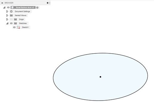
First I started with a sketch of a 40mm circle:
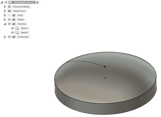
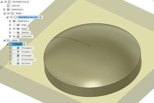
Then I extruded the circle down 5mm to form a stubby cylinder. Going the other way I defined a point 5mm above the top of the cylinder and did a loft from the circle at the top of the cylinder to the point. This gave me a dome and overall created my button.
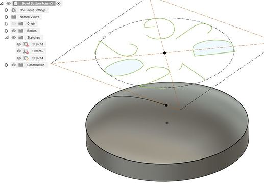
Next, on a new plane I defined my initials and the year and told F360 to make them follow the path of a circle. The only trick was to explode the text so it was just paths so I could do the next step.
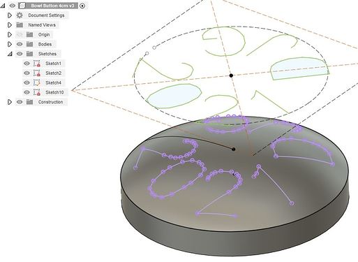
Next I created a projected sketch onto the face of the button using the paths of the text. This gave me 3D text that followed the surface of my model. The model was now complete.
I then switched from Fusion 360 Design mode to Manufacturing mode. Here I did a setup that did three things: (1) it defined my stock to be 10mm x 10mm larger then my model, (2) it put the origin on the top of the stock in the far left/front corner, and (3) it let me tell F360 to considered my model when it was generating 3D toolpaths.
The Flyfisher604 Post Processor (PP) I’ve been writing produces GCode from your F360 toolpaths. One of its features is to allow you to scale the feedrates used by F360 to ensure you don’t over tax the MPCNC’s Z axis, that can’t cut or travel as fast as its X and Y axis. I decided that I would use several different 3D milling operations to exercise the scaling functionality of the PP.
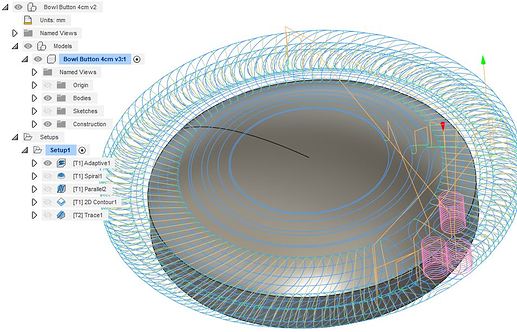
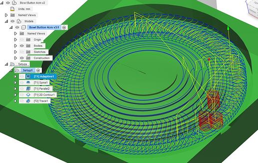
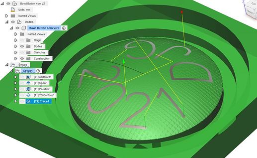
The first operation was a 3D Adaptive Clearing roughing operation with a 2mm stepdown and a 0.5mm material leave. I defined it by just selecting the first circle (just below the dome). F360 built all the operations and worked around my model. Here are two views: just the model with the toolpath and then the stock removed with the toolpath.
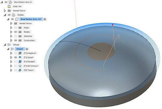
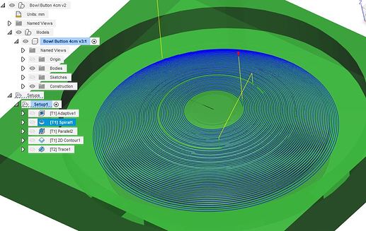
I then asked F360 to do a 3D Spiral finishing pass of the dome (0mm leave). Again I just selected the first circle below the dome. What I found amazing was that I was still just using the 1/8mm flat mill. I told F360 that it needed to consider the points of contact so it didn’t gouge the dome. You can see the travel path where it picked up the tool and reset it so that it started cutting on the inside edge of the tool.
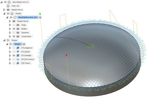
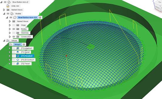
I then smoothed the dome with a 3D Parallel milling finishing operation and told F360 that it should leave 0mm above the model and that it should also do a perpendicular pass. Again this was on the curved dome’s surface and I defined this in a couple of clicks and it happened with a flat mill!
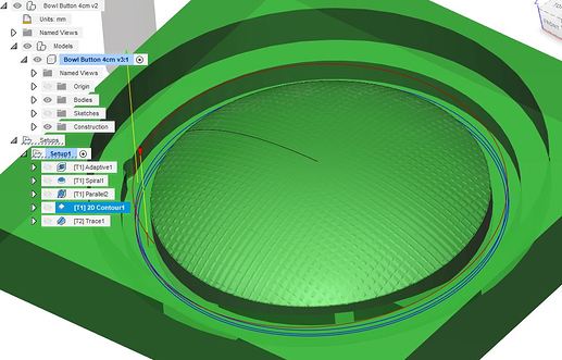
Next I did a 2D Contour operation and selected the circle below the dome and the bottom depth of the cut. I told F360 to do a roughing pass that left 0.5mm, to go down in 2mm steps, and to use a ramp to get there (I wanted Z changing at the same time to exercise the PP).
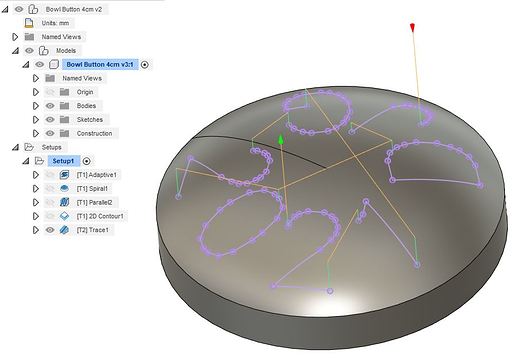
Finally I told F360 to do a Trace milling operation. A trace operation follows a path in 3D so it was perfect to engrave the text on the surface of the dome. To define the operation I selected the 7 paths that made up the text (remember I exploded the text into paths) and told it to offset the tool by -0.75mm axially so that it cut 0.75mm into the dome.
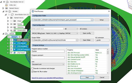
The final step before really cutting something was to run the Post Processor twice. Once for the first 4 operations that all use the 1/8in flat mill and then once more for the engraving operation that uses a v-bit (F360 Personal doesn’t allow a tool changes in a single PP run so two separate runs of the PP were needed).
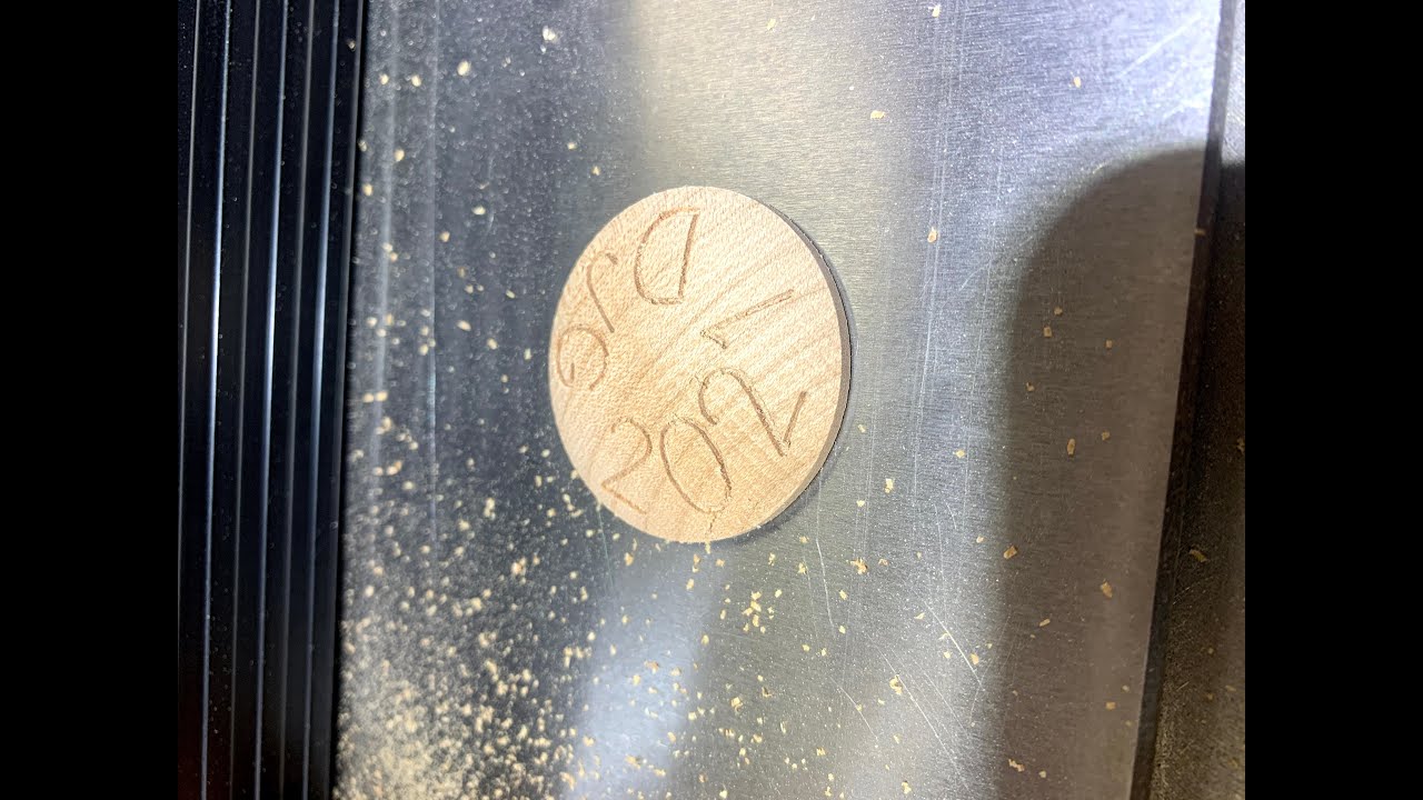
Then there was nothing left other then to put a waste piece of maple into the MPCNC and make some chips. The final disk was released from the block by making a bandsaw cut parallel to the surface.
All in all it was a fun little project that taught me the power of F360’s 3D milling operations and tested the Flyfisher604 PP’s ability to scale feedrates . When I reviewed the GCode generated by the PP I could clearly see the feedrates scaled many times to keep Z within its defined limits. During the cut I saw no issues. All around I’m happy with the results and the tools.
