Bow before Z

Hey,

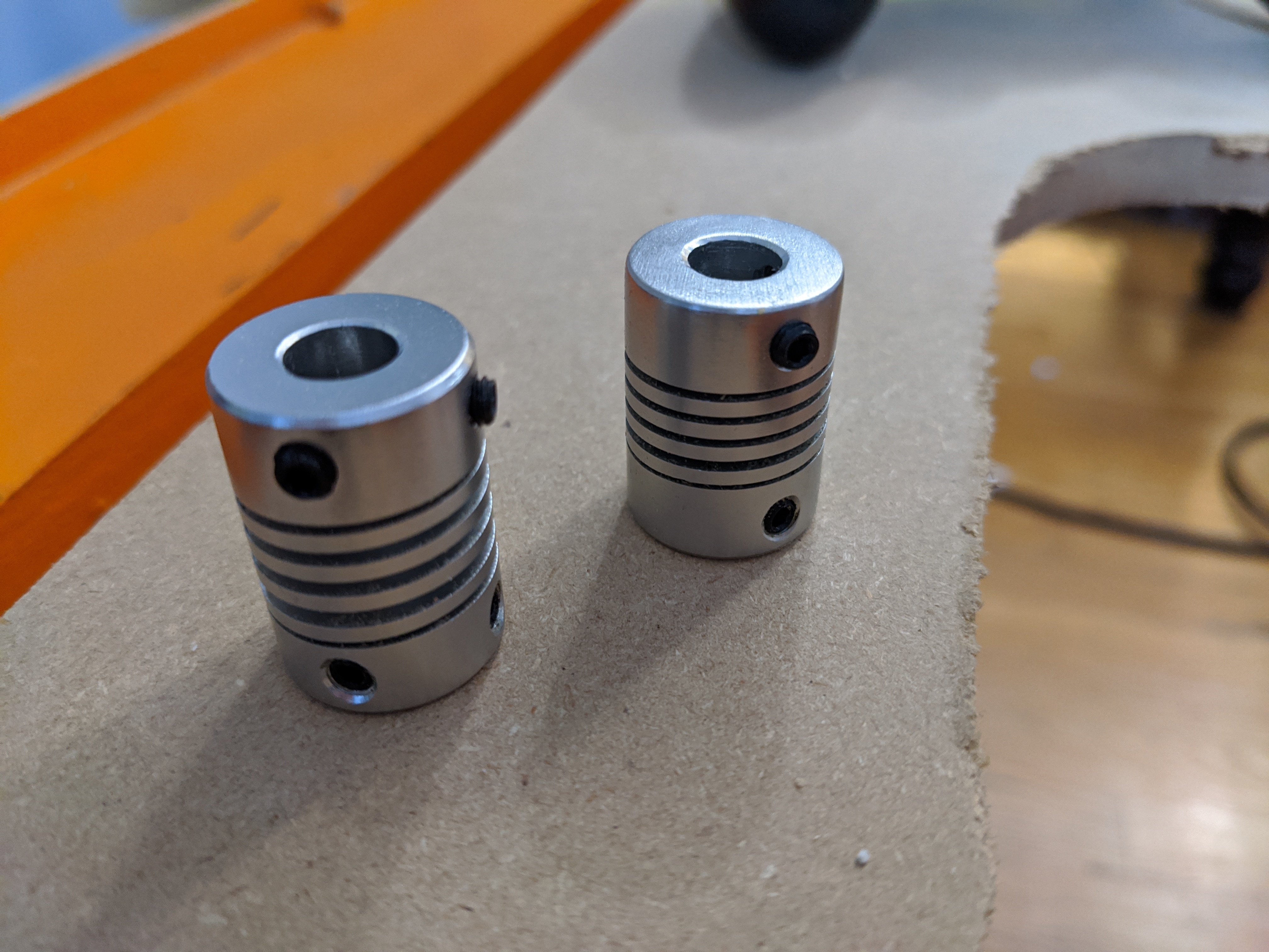
So, you cut power to the motors, one side plunges down, the other can be pushed down fairly easy. Both are touching the bottom. You jog Z back up and one side goes up before the other, what happened? The springy part of the coupler is a half to a quarter turn different on each side. OK, you cut power again, drop it, and turn each one until they look the same, now it rises in unison, but how accurate is that?

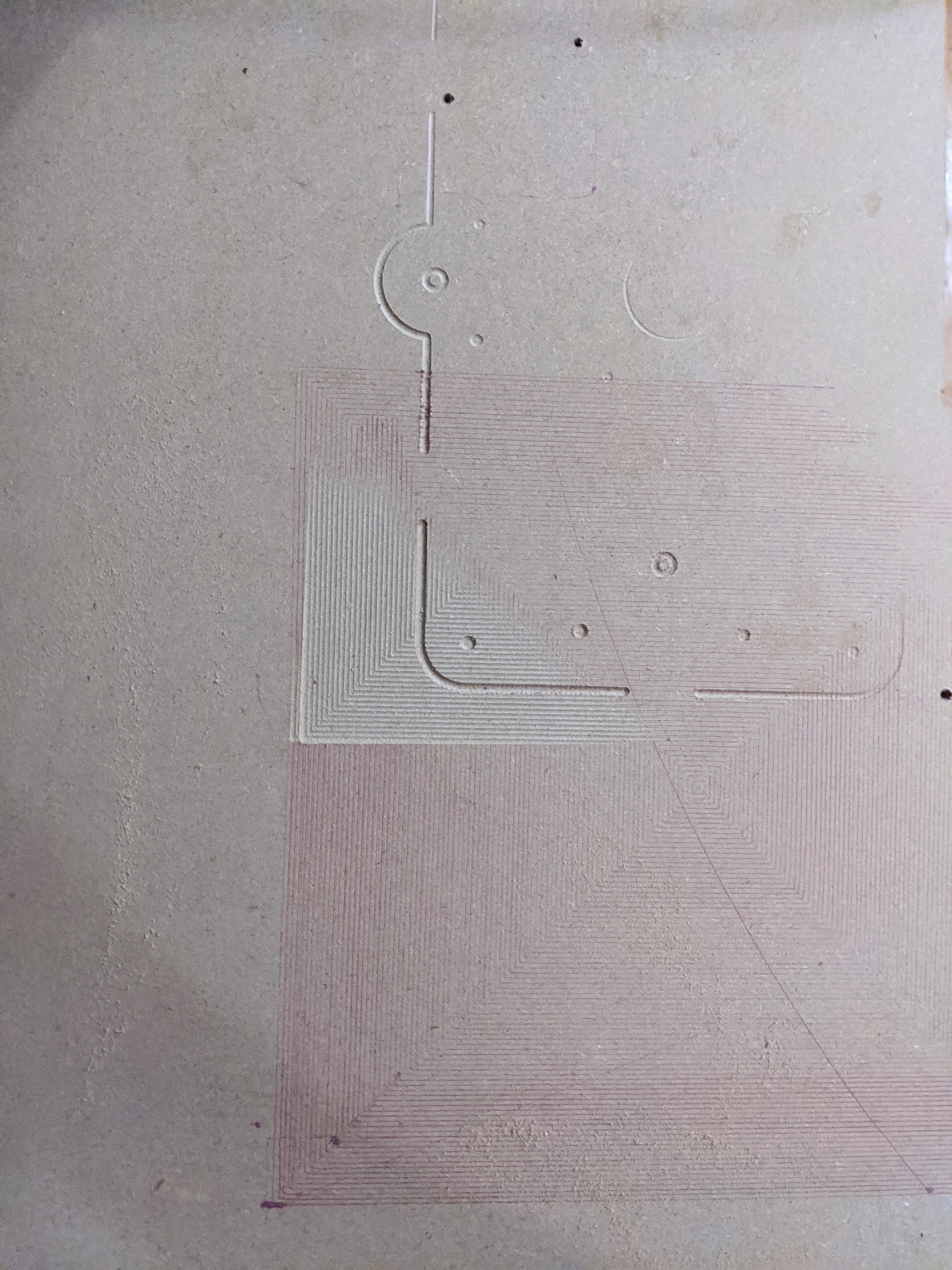
I did several hours worth of bed leveling with a 1/8" bit to see what the result would be (and to sort of stress test the accuracy and long run time of the machine before cutting good wood). I forgot to take my pen out and it ran out of ink, but it kept running over the same lines, so squares seem pretty accurate to the eye. There is a slight rise of a few mm near the edge, and slight sag because I need to do a proper table, I knew that, but I think I may need a better Z calibration or homing so that at least one source of inaccuracy is eliminated.

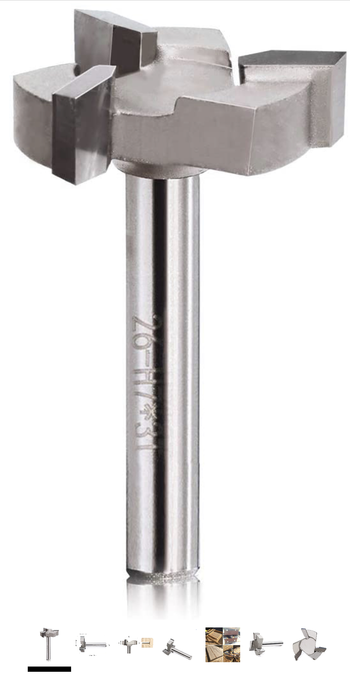
I have been putting a metal straight edge under the bit and lowering the router until it lands on it, the move z up 1, remove it, lower Z 2.1 and that is pretty close, the cutting part of the bit still not really in play. Regardless of how close I set Z it should be the same along X.

The cutout outline (through 1/4"" plywood) goes from no contact to a few mm deep in the space of a foot wide, I am thinking this isn’t all sag, but one end being slightly higher than the other when starting. I should probably re-tighten the brass ring a bit as well, the quest for simultaneous freefall isn’t worth losing accuracy, and that requires the router be centered for me.

Solutions?

Has anyone run the Z with the extruder motor (mini rambo)? Is that overkill, is there a better solution? Can you avoid stretch in the coupler so when the motor engages, there is immediate movement? Where does one place an end stop for the Z axis? I have momentary switches, reed switches and magnets, proximity sensors on the way, what solutions have you come up with?

Cheers!

Inside the couplers, the motor shaft should be resting on the screw. That gives you a good point of reference between those two and it won’t change as long as your grub screws stay tight.

Before I engage my Z motors, I give each one a 1/4 turn to lift that side up, and it falls down until the printed parts are touching. That is good enough for me.

You can do dual endstops on the Z. Set the extruders to zero, set the number of Z drivers to 2 and set the second Z endstop to xmax. If you set Z home dir to +1, you will use the zmax port. I’m not sure it is worth it on the LR. Because it is so quick to start it at the bottom.

I got one of those z probes from the shop that he’s got like $10 … https://shop.v1engineering.com/collections/miscellaneous/products/tiny-touch-plate … $6 bucks now.I was worried my bit would kill it cuz it’s a thin metal. But it works just have to set up, I don’t know how it is on the rambo board, but I just put it on one of the empty end stop ports on my cheapo cncshield. From my limited experience Cutting on the machine , I did get myself one of these…


and that helped level out the waste board in high spots in relation to the rails on its uneven points.

Hope that helps

1 Like

Glad to know I’m not the only one with the issue. I have a series of orders from aliexpress clogging up the postal system, a surface bit is one of them. :slight_smile: I am thinking though that surfacing the work piece is going to be go to, took forever to do a 250 x 250 square, granted a 3mm bit vs 1 inch is going to be slow.

Z-Probe, not too concerned about that yet, it’s just a clamp on the bit to complete the circuit, like you say, easy enough. I am still in macro land of mm’s not sub mms. :slight_smile: I’d buy it from Ryan, but shipping would kill that idea.

I know where the larger discrepancy is, the wood I screwed into the side of the table is slightly lower in that corner. Have to nudge it up ever so slightly. Or just make a better table.

Cheers!

The tightness is good until I goof and try to go too negative and it ends up stretching. I did follow the instructions and have the screw just at the bouncy border and the motor shaft lying on it.

Think I found the culprit, it was me all along. I just replaced the couplers, will see if it improves things. I know why then sell them in bunches now.

3 Likes

I think he’s out in Cali, I’m in Miami took 2 days to get here… I too have stuff waiting from Ali express… 3 months in the waiting game, atleast for us in the states a couple bucks to get stuff in acouple days is sometimes worth the 3-4$…

I did have issues with my couplers I think acouple people have, once you get them right then it’s smooth sailing also I noticed when I dry fitted it was kind of janky, until I added the lube on the lead screw, my lead screws are like 400mm like 2x the size of my rails, might look into cutting those to the right size may add additional stress on the nut, since it’s not held down anywhere else, food for thought if you got long lead screws

Also make sure your motor settings are right in whatever firmware your using if you got it set to high it’ll skip steps , I ran mine through a huge range, the motors can handle a lot if you got decent ones, but remember the feeds and speeds on the cutting is going to be your bottle neck, so no reason to have crazy motor control speeds, especially on the z-axis doesn’t move as much as the x-y axis .That helps keep that jitter of missteps out

Just found this looks accurate https://zalophusdokdo.github.io/StepperMotorsCalculator/en/index.html

If it’s not a hardware misalignment issue, but we have 2 separate motors on each side, if one is mis stepping on one side it will create an uneven effect over the range of the gantry…

I’m a bit embarrassed to admit that I have done this repeatedly.

It is possible to take the couplers off, squish them back together, and re-install them a time or two.

I do replace them after I’ve stretched them a couple of times, or If I REALLY stretch them.

I’ve started putting a tiny bit of “pre-load” on the couplers. By that I mean I tighten the coupler on the stepper, get the leadscrew in contact with the stepper shaft, and then stretch the coupler a tiny bit (like 1 mm) while tightening the coupler on the leadscrew.

This seems to result in slightly better consistency in my Z height settings.

1 Like

Unfortunately, I am in Canada, and the trucks have to be compensated for a large speed bump at the border, apparently if we all pitch in $50 per trip truckers can clean the resulting coffee stains off their tiki bobble heads.

I added lube, I think if you work piece is above the point where the plastic meets the plastic, if you drop down a few mm too far, the worst case is the wheels lift up. Mine are 400 mm, I don’t feel they are the problem right now, and having them has allowed me to raise the router up further, for maintenance like replacing the plate.

It’s more me forgetting to change the jog size or do a g92 at the proper height before starting.

I am using 16 tooth gt2 pulleys, and Ryan’s firmware, my tests seem accurate enough, after factoring in human error.

Cheers!

I had a package of 6, so still have a few spares left. :slight_smile: I tried squatting them, haven’t seem much difference really , still an uneven set, may need to add a heat gun to the mix. I may order a bag of 20 or so to keep in stock, but since I will never make a mistake again, everything is good. :slight_smile:

Chers!