Bigtreetech octopus on Lowrider V3

Hey @jamiek / anyone, are you using buck convertor to power your Pi, if so which? Or are you happily powering your Pi off the Octopus board, maybe that’s ok for Pi 3+. But for Pi 4, am less confident.

From Jamie’s build topic Outdoor IDEX build - #69 by jamiek

Octopus User Guide says…

  • Max 5V 8A on page 7
  • Board has 5V headers (J26) specifically to Power Pi on page 10. Can see J26 Header/Pins, but searching for J26 on Schematic didn’t reveal max current for the header. Am assuming it’s good for what ever the board and J26 dupont pins are capable of (3amp).

Planning to run Pi 4 (acquired during the before times) which consumes ~3.0A, currently leaning towards decided to give the precious Pi it’s own buck convertor power supply isolated from whatever is going on with the Octopus connected steppers/fans/lights/etc… Also thinking probably better (decoupled fate/cycling) for the Pi to not be harshly reset as frequently as how often I need to reset/abort Octopus job.

Yes, I am using a buck converter for the Pi (far left in the picture above).

I had seen the 5V for the Raspberry Pi connection but it was after I had already hooked up the buck converter. It does make me curious. If it’s intended for the Pi, I would hope it could deliver enough current. It would be nice if it worked. It’s worth an experiment. I’m not sure if I have a suitable resistor, but maybe I can gang a bunch together, or maybe even a stepper can act briefly as a low-value resistor.

Or even just hook up the Pi and run a cpu-intensive program and see if the brown-out indicator trips.

1 Like

Thanks for the info and ideas Jamie.

Planning to keep Pi power separate, at least until my LR3 is working again.

Found an unused DROK Buck Converter 12v to 5v max 5A among my unused adapters. Uses synchronous high efficiency rectification, great, when it works… Wondering if they can fail latched sending full input voltage to destroy target device. Will test before using, but, might end up just using official Pi power supply if/when I find it.

I use a buck/boost converter on my pi. I have one on my printer too.

The header 5V pins are after any psu filtering circuitry on the pi itself. So a usb connection is better. In the last install, I soldered directly to the pads on the bottom of the USB power in port. That is my favorite way to do it. The gpio pins seem to leave me with a lot of warnings.

1 Like

I prefer to cut a cheap USB cable to power my pi.

1 Like

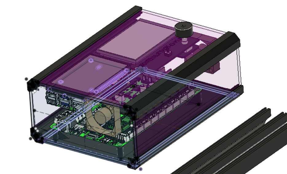
@niget2002, do you have an Octopus? Would love to see more examples of LR3’s powered by Octopus + Pi.

Feel like I’m reinventing the wheel here and someone’s already done this better already?

No. I’m running my pi attached to a MPCNC running a smaller controller.

1 Like

Anyone have Octopus based layouts/setups they’d like to share?

Currently wiring up, setting jumpers, firmware and such…

For TMC2209 Drivers looks like we set jumpers for UART mode. From 3.2 in Octopus User Guide.

For SKR Pro 1.2, for the PCB’s TFT connector, I removed the plastic female connector to help the Dupont cable make more secure connection. Anyone done the same for Octopus’s TFT connector?

EDIT: Ended up removing JST connector housings for steppers, endstops and tft. Yet to power up and figure out if I broke something…

1 Like

Boardkiller Aza. :sweat_smile: Wishing you luck.

@Antwanvb, thank you for creating and sharing these edits. btw - I like the custom “Wood Menu” you added.

Ran into small problem…
problem : I built sources you mentioned from Release Marlin 2.0.9.5 · MarlinFirmware/Marlin · GitHub, with your edits applied. But ran into build error with …/…/…/_Bootscreen.h not being found.
workaround : Copied snapshot from newer Marlin build I have, https://github.com/aaronse/marlin_2.1.1_515/raw/master/Marlin/_Bootscreen.h, after that was able to build and deploy (copy firmware.bin to SD card, etc…).

From Octopus User Guide, looks like we can deploy firmware directly to Octopus board over the USB cable via ‘DFU’ :man_shrugging: . However, that’ll wipe the bootloader that understands how to read firmware.bin from the SD Card. So, for now, am doing firmware updates via SD card, until if/when I know how to rollback/revert bootloader changes made by DFU USB firmware updates. Pointers appreciated if anyone’s figured that out already?

Currently seeing TFT3.0-E3 “TMC Connection Error”, this is expected because my board doesn’t have any power cables plugged in. No steppers, no endstops. Time to hook everything up…

Also, planning to reapply a diff of Antwan’s Octopus related Marlin 2.0.9.5 edits to my snapshot of Marlin 2.1.1 with V1E Lowrider Dual endstop edits applied by V1E MarlinBuilder. Maybe someone’s done this already (running Marlin 2.1.1 on Octopus)?

Need to figure out BTT’s ESP32 module next…

1 Like

Created separate topic getting BTT’s ESP32 module working with Octopus at Firmware for BigTreeTech ESP32U ESP32E Module for Octopus (or SKR3/ SKR 3 EZ/ SKR 2)

1 Like

“TMC Connection Error” was due to me not installing drivers correctly. Ignoring anything’s possible if you edit pins_BTT_OCTOPUS_V1_common.h… For stock LR3, the drivers should be installed next to each other, no gaps (the mistake I made). So, Driver0 thru to Driver4 should be installed. For my Octopus board, the drivers are very a tight fit (drivers are too wide for the pin headers with zero gap between the drivers). Worked around by inserting and pressing all drivers down at same time.

Output from M119 and M122 TMC Debugging helped me troubleshoot, found thanks to this and this topic.

Flashed ESP32U via Platform IO with ESP3D compiled to 32 bit. Can connect to ESP3D AP from laptop, but ESP3D terminal commands are not being processed by Marlin. Still debugging, guessing this is related to Marlin 2.0.9.5 being used instead of the new version that Ryan recommended in the Headless SKR thread. Planning to update my marlin_2.1.1_515 snapshot with Octopus related edits folks here applied to 2.0.9.5 so I can have it all :slight_smile: If someone’s done this already, please let me know…

5 Likes

I just got the pricing I was waiting for from BTT. I am 90% sure I will be moving to the octopus soon. I will get a test branch into the marlin builder this week I hope, the board is sitting on my desk ready for testing.

Hopefully that helps?

I hope that spurs me into writing up the headless guide. I have to look over the headless notes you posted awhile back Aza, that should get us rolling.

4 Likes

Cheers Ryan, that does help. I started digging into Marlin Builder, mainly out of curiosity, nice setup. Currently tinkering with that and the marlin_2.1.1_515 snapshot. Will contribute back if I can.

Planning to update my Octopus notes and ESP3D notes as I make progress. Currently in a rough skeleton state, expecting they’ll be refined as they’re fleshed out. You/others are welcome to reference/use/copy, but recommend ignoring them for the next few days while they’re churned into reality. Cheers!

Intentionally posting updates here incase someone’s done this stuff already… for example

1 Like

Short: Ran into, but fixed, ESP3D and touch plate issues. Shared Marlin 2.1.1 snapshot.

Long:
Currently pushing edits to a Marlin 2.1.1 snapshot to get my Octopus board working. Ideally, after figuring out correct settings, separate set of edits extending MarlinBuilder will happen.

Started out with Marlin 2.1.1 515DL snapshot generated by MarlinBuilder for SKR Pro dual endstop LR machine. Applied Octopus related edits shared earlier in this topic for Marlin 2.0.9.5. Currently builds and deploys, USB host can connect, send gcode and receive responses.

However… although ESP32U wifi module is running ESP3D, terminal gcode commands sent from the wifi module are not connecting/executing. Also, TFT isn’t displaying Wifi module messages, so digging into how they should be connecting (maybe serial and/or pinout changes needed?). Still learning/investigating…

2023/2/5 Edit: Fixed connectivity between Octopus and ESP3D, needed to edit configured serial ports and baudrate.

2023/2/11 Edit: Z probe isn’t working, no motion when G38.2 Z0. Strangely M119 reports ok before using G38.2, but then reports triggered afterwards, even though there’s no motion. Checked wiring, guessing firmware related, still investigating…

2023/2/12 Edit: Updated Marlin 2.1.1 snapshot with this commit

  • Fixed Z Probe, wrong Z probe pin was configured, should’ve been PB7 == 23.
  • Fixed Marlin serial2 wifi (3) baud rate back to 250000. Needed to update ESP3D settings to be the same rate (via ESP3D settings web ui).
  • Investigating why file upload to SD isn’t possible. #define for SD was enabled, so can read Octopus SD card, can read/write to flash (very small…) but can’t write to SD via ESP3D. Obviously this is very pants.

2023/2/16 Status: Z probe not working for me, guessing I messed up firmware edit. M119 reports expected trigger/ok for plate. actively investigating will provide update… No movement when G38.2 Z0. Am sharing incase anyone’s using the firmware snapshot I shared in this topic

2023/2/21 Status: Fixed Z Touch Plate Probe by using #define Z_MIN_PROBE_PIN PG11 which is for Diag 3 connector, see commit. Learnt about some of Marlin’s internals along the way, bonus!

Was unable to get V1E touch plate to with with PB7. Figured out by temporarily littering code with traces… diff_no_probe_temp_traces.zip (2.7 KB)

Observed inconsistent read values, seemed-like/suspected PB7 was floating. Double checked schematic and saw pullup and pulldown resistors marked “NC” (not connected?). So, don’t think there’s any pullup/pulldown resistor on my Octopus for PB7. Used scope to confirm voltage hovers around 0.

Where as the Diag 0 - Diag 7 connectors clearly have pullup resistors (per schematic), so am using those for endstops/touch-plate/switches.

If someone’s happily using PB7 for their touch plate, am curious to know how they wired up, did they add their own pullup resistor, or did I do something wrong, wiring/firmware?

4 Likes

Any ETA on when the Octopus Pro will be a standard store offering ?

Thanks much.

1 Like

No, I have not tested one yet and I think there is a revision in the works from them.

1 Like

It looks like the “BTT Octopus Max EZ” (using the “cardslot/blade” form factor drivers) is the replacement for the “Octopus Pro” giving the OP a very short lifespan.

I’m not sure the EZ factor will replace it. They cost more for almost no benefit.

1 Like

The major deltas appear to be the following. As to if they will all be used …

  • M4 168Mhz vs M7 550Mhz processor
  • 8 vs 8+2 drivers
  • Socket vs Blade drivers
  • [5,12]V fans vs [5,12,24]V fans
  • Reduced # of jumpers (to reduce pilot error)
  • Direct power for RaspPi
  • Added “eFuse”
  • CAN support
  • Accelerometer port

Octopus Pro:

【Main Control Chip】The main control board uses 32-bit ARM-level Cortex-M4 series STM32H723ZE/ STM32F429ZE / STM32F446ZE chip with a frequency of up to 168MHz and the flash is 1MB.

【Support 60V Input】Supports up to 8 3D printer motherboards with a maximum 60V stepper motor. The motor drive power supply supports up to 60V input (only for the motor drive power supply).

【6 Controllable Fans】Up to 6 controllable fans, two normally open fans, and both support power supply voltage, 12V, 5V options.

【Update Firmware: Klipper/Marlin/RRF】Supports firmware update via DFU mode. This is where the firmware is sent to the board directly from the PC and does not require a bootloader however this method is not recommended for novice users as discussed later in this document.

【Level conversion IC】Supports proximity sensor, jumper optional pull-up resistor, supports more models, supports BL Touch.

Octopus Max EZ:

  1. 32-bit 550 MHz ARM Cortex-M7 series STM32H723ZET6 MCU
  2. Onboard BOOT button to enable DFU mode to update the bootloader
  3. The thermistor circuit is protected to prevent MCU damage from shorted heated bed and heater cartridge connections
  4. Selectable voltage (24V, 12V, 5V) for CNC fan, no more need for external stepdown
    thus preventing board damage from user error
  5. Upgraded with eFuse protection, which response faster with strong protection,
    effectively protecting the motherboard from being damaged caused by short circuits,
    over-current, electric spark, etc.
  6. MCU firmware can be upgraded via SD card, or use DFU via Klipper’s make flash
    command
  7. 10 EZ driver sockets, working with the pinless driver, safer to use; Onboard SPI and
    UART, can be used by simply setting in the firmware, no need for a jumper
  8. Support power loss recovery, filament runout sensor, CAN, auto power-off, BL Touch, RGB, etc
  9. Replaceable fuse for easy maintenance
  10. 3 x 4 pins fan ports, also for connecting the water cooling system
  11. Onboard proximity switch port, supports NPN and PNP types, 24V, 12V, and 5V voltage selectable
  12. Onboard SPI interface for connecting acceleration sensor to enable Klipper’s input shaping

Update:

2 Likes