Hi all. I’ve encountered the issues with big circles again. I’ve looked through old threads and tried all the different solutions. (reducing speed, turning arcs off and on and back again, running the code just to see if it’s the viewers fault, etc)
Here is the svg:
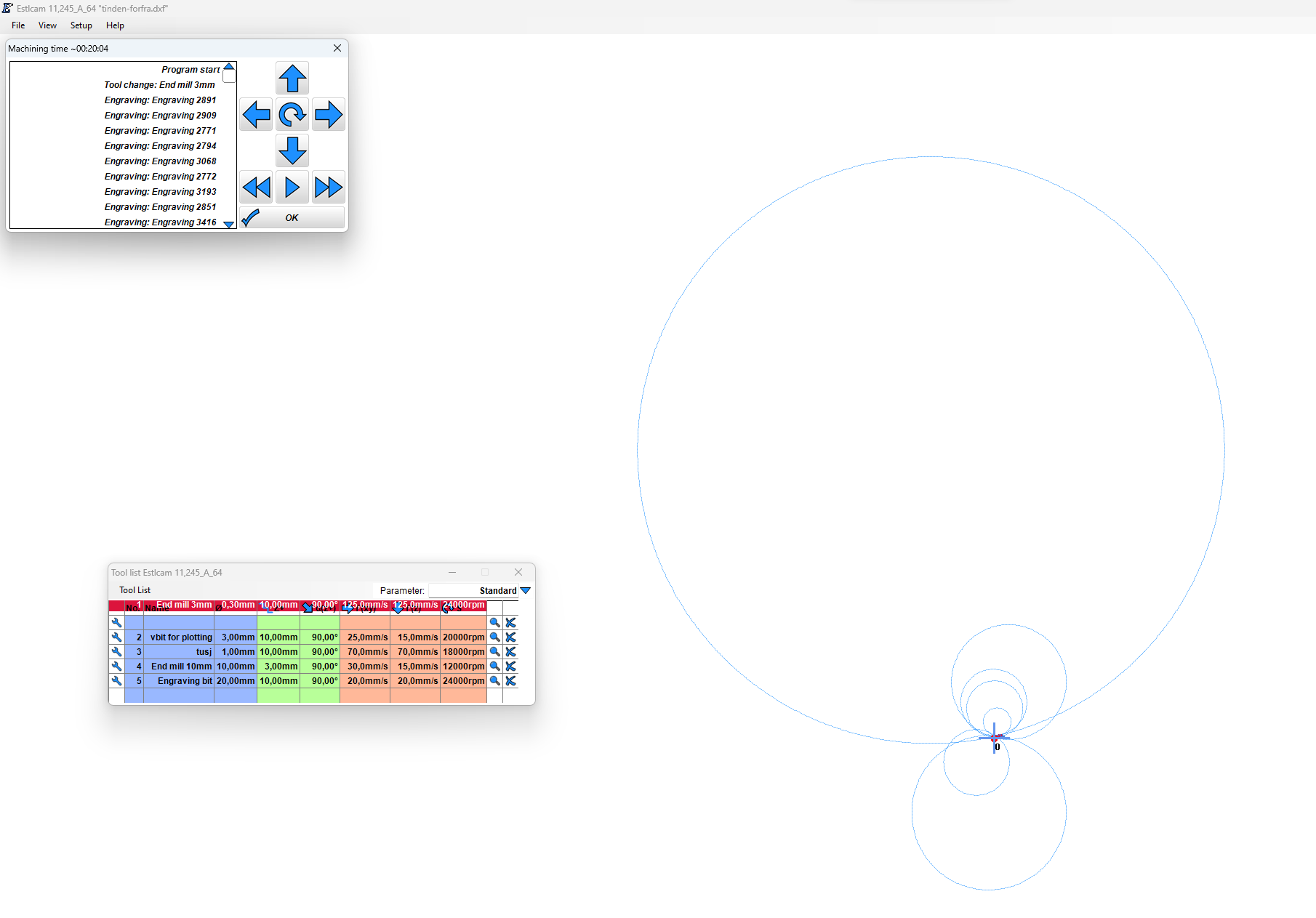
And here is how it looks like in Estlcam (v. 11.245)
Hmm, the usual “the lines are not closed” might not work directly, but did you try loading the stl into Prusa Slicer, checking whether it throws any errors and offering to fix it? Then you’d know it’s the models fault.
For those that don’t know, zooming in at the origin will show that the (presumably auto-selected open… and closed) engrave paths are all there. I don’t know what caused those circles, the drawing does have some odd (doubled) straight line bits, but using the Inkscape Path : Simplify function on the SVG was all it took to get a circle free Preview.
… v12.042 chokes on the original file, but does fine with the simplified one (pretty much the same paths/estimated time)… when set to pixels. The v11 image/time was with my default millimeters (huge, ~1900mm wide) and worked fine, but the same file/setting in v12 had zoom issues - the edit screen drawing/paths were only visible for one or two zoom clicks (blank otherwise).
…
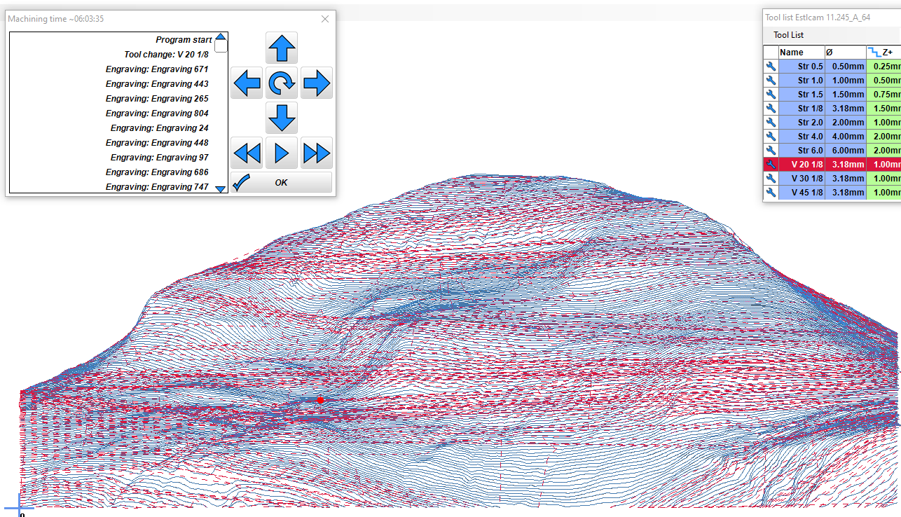
While the paths in the main/edit window are not always accurate, the Preview tool paths are extremely accurate and reliable. With the exception of any tool change paths, the Preview is a what you see is what you’ll get in the controller window. I’m not aware of any configuration changes (speed, arcs, etc.) that will have any effect on the Preview paths.
I’ve corrected it for version 12 and just uploaded an update.
(but it still says 12.042 from 17th January - I haven’t increased the version number yet).
Old affected files are not automatically repaired - press Alt + F5 to force a recalculation.
Version 11 unfortunately cannot be updated anymore. Any changes there would mean losing support for older windows versions which is something I want to avoid.
Big, misplaced circles can however also be caused by mismatching arc format settings in the CAM and control software setup. Most controllers use relative I/J coordinates, but some require absolute coordinates. This setting can be changed in Estlcam in the CNC Program settings dialog.
This wasn’t the issue in this case, but if all arcs are wrong it is usually this setting.
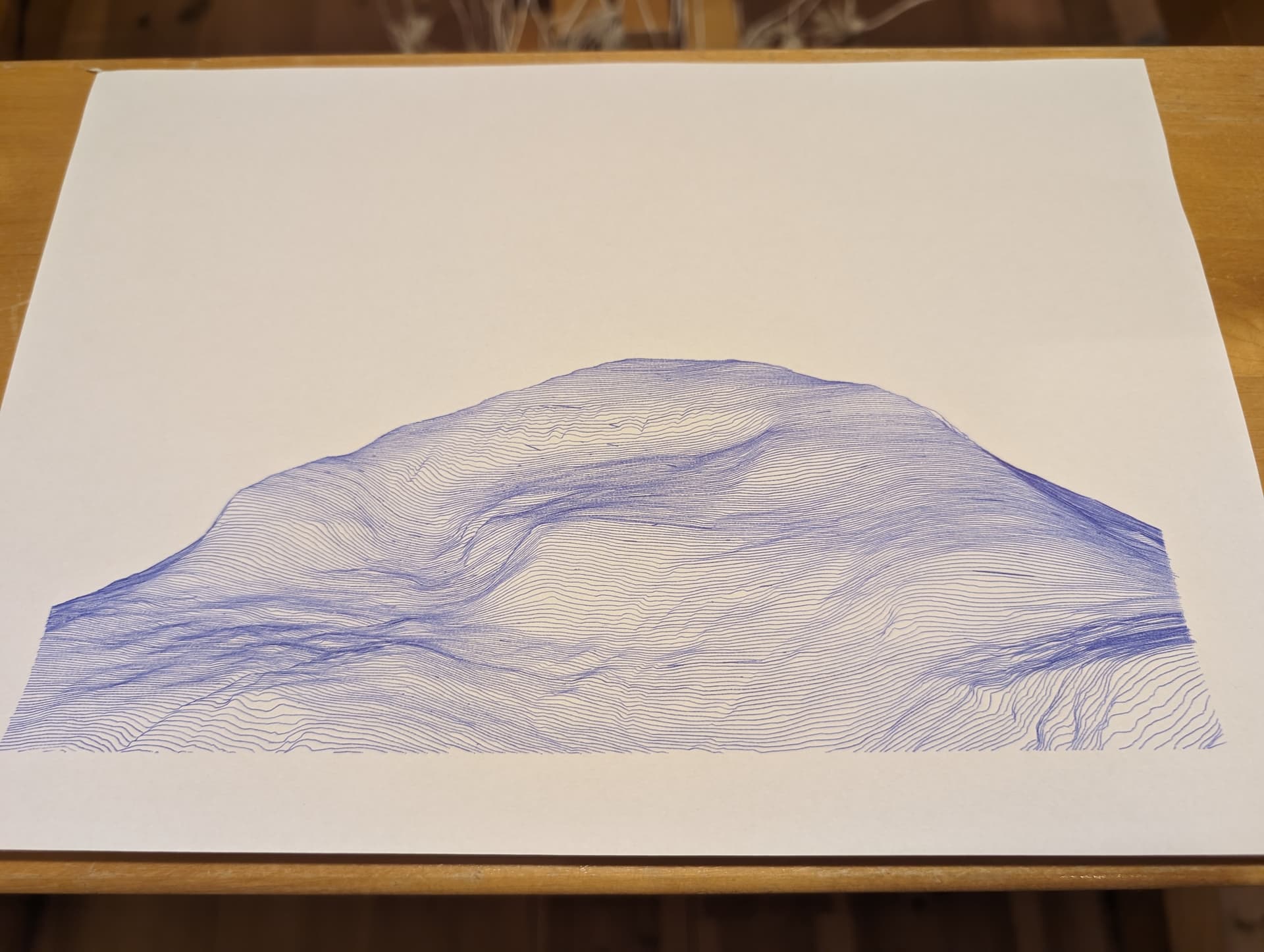
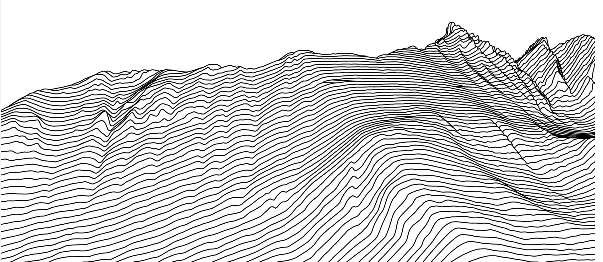
I did the same as you did - and it worked. No exploding circles anymore. Thanks! But - simplify does alter the impression a little bit, the whole mountain seems more smooth. The ragged (and accurate) original lines gave somehow a more realistic appearance.
I did try v12(from monday!), but resizing the dxf didn’t work(the program hung). Trying to autocreate the engraving paths didn’t work either. In hindsight I could have resized the vector file in Inkscape before importing in Estlcam. But I’ll keep it in mind next time! Thanks for chiming in!
That’s pretty cool. Is there a tool for that, e.g. could I make one of Mt Baker?
If you have Setup : Basic : Units import set to ‘Ask each time’ you can set the width you want before opening the file.
Using the Select menu tools has changed in v12 (hover over the Select icon for details). In this case click on the Select tool, press/hold the D key and left-click on the drawing to select it and then click the Resize tool.
…to clarify, both drawing resize methods and auto-create worked for me using the Monday v12 and the original image.
The autocreate has been fixed, too yesterday.
Resizing should also work (just tried) - but it is a lot of lines, and may appear stuck sometimes until it catches up.
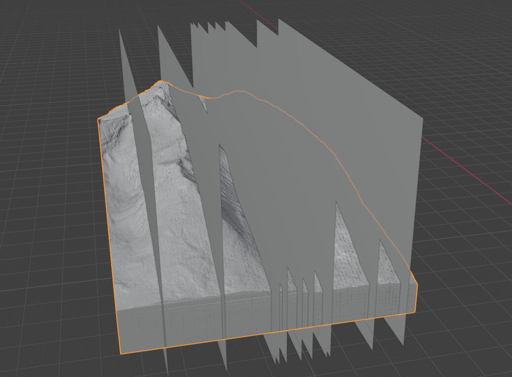
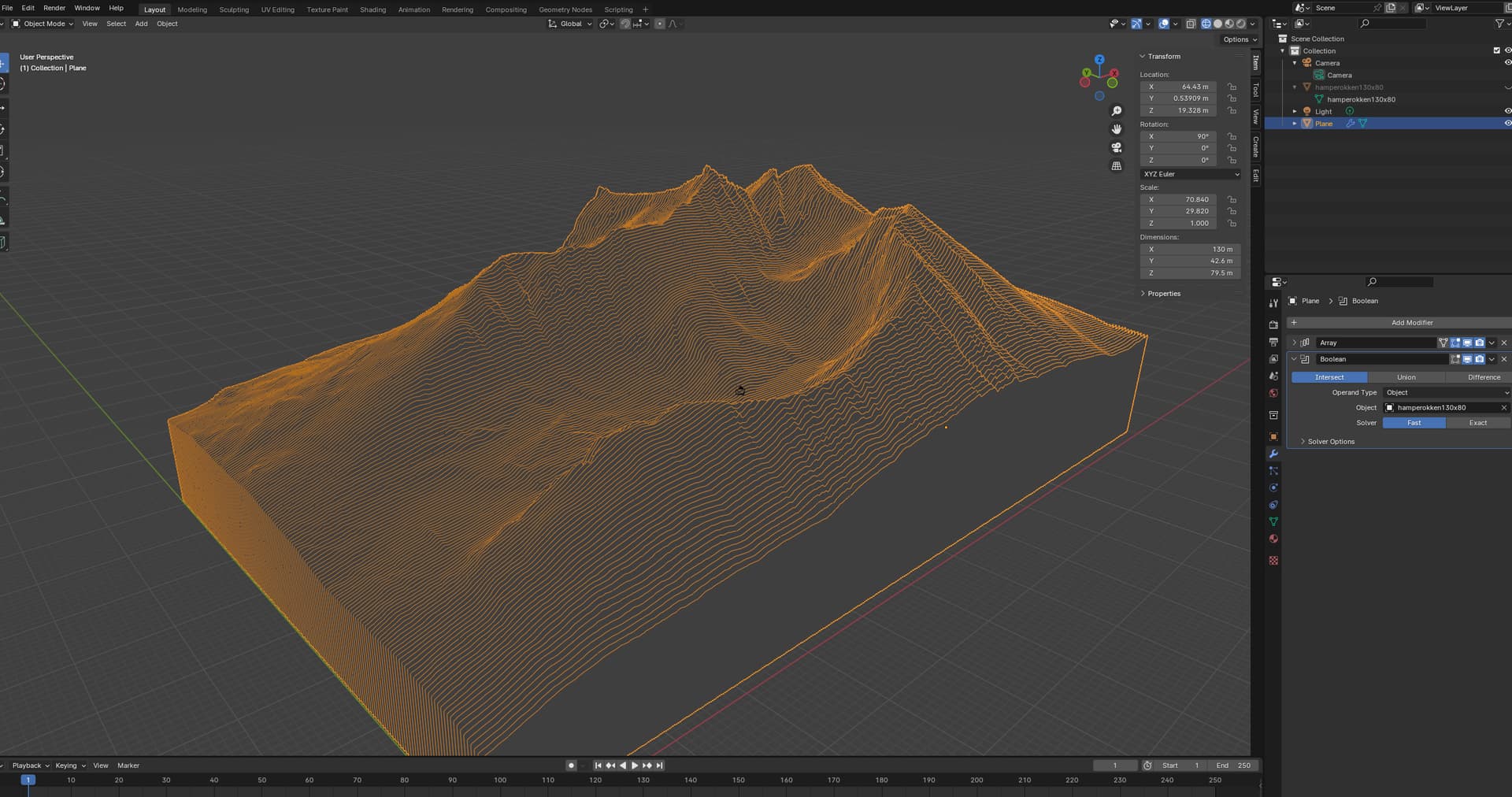
Sorry, there are no automated tools for this. You need to get a 3d model of said landscape. (terrain2stl is a great tool). Then you have to import it in blender and use plane->array->boolean intersect. This method is quite messy, intersecting the planes with the 3d model can be really difficult to accomplish in a nice way. Here is a mountain that I’m working on now:
You’ll see how there are several planes that havent intersected, and God knows why… I’ve tried solidifying the model and the planes, welding and what not. Blender is a mouthful!
Update edit: I figured out the planes with broken intersecting. I don’t know what PRECISELY made the difference, but I used solidify, weld and remesh on the 3dmodel. I guess it should close any holes and issues with the mesh.
Thanks a lot for keeping in touch with users and improving based on feedback and input! I guess I’ll take the leap and figure v12 out, especially since you are on the ball