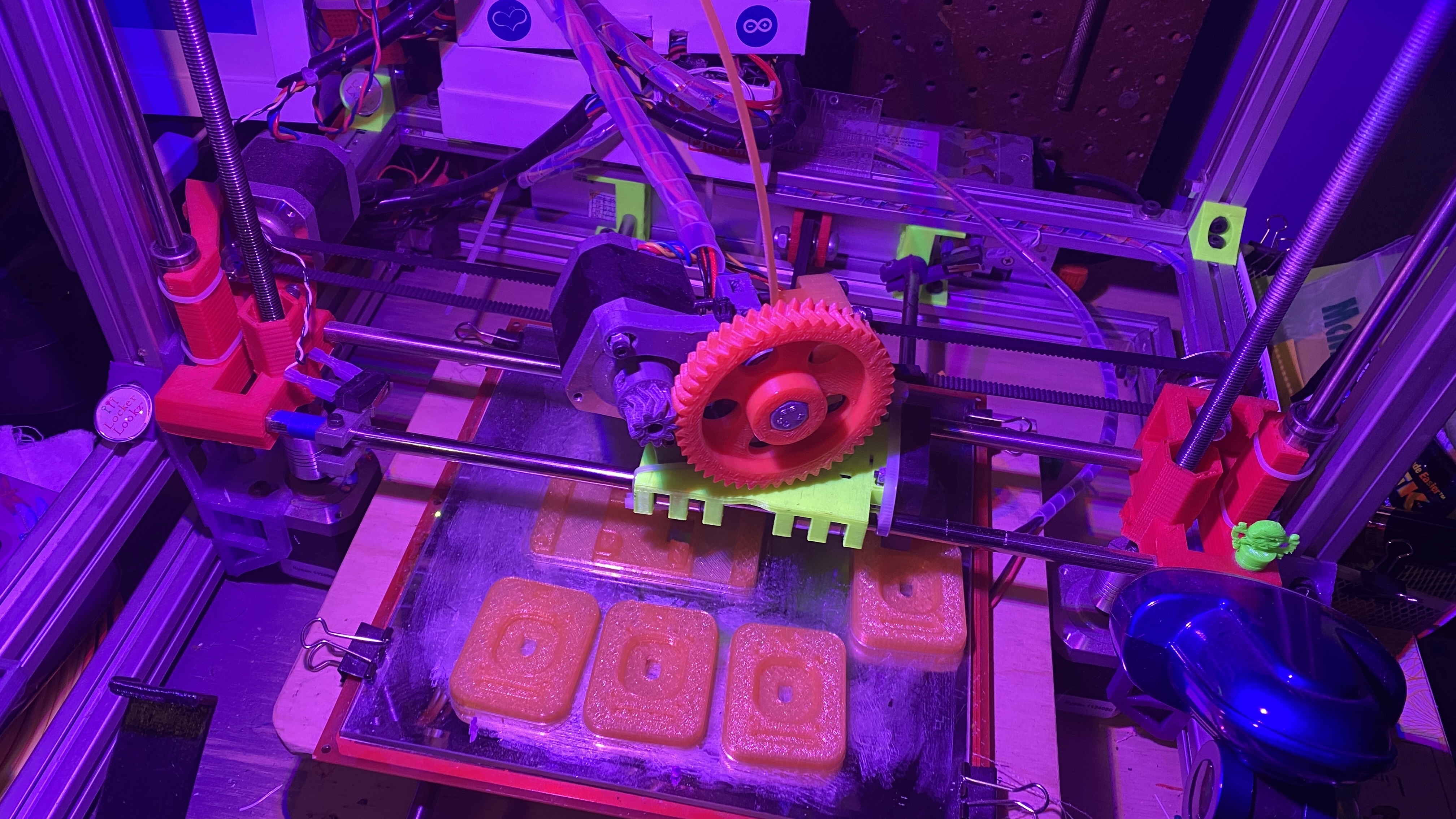
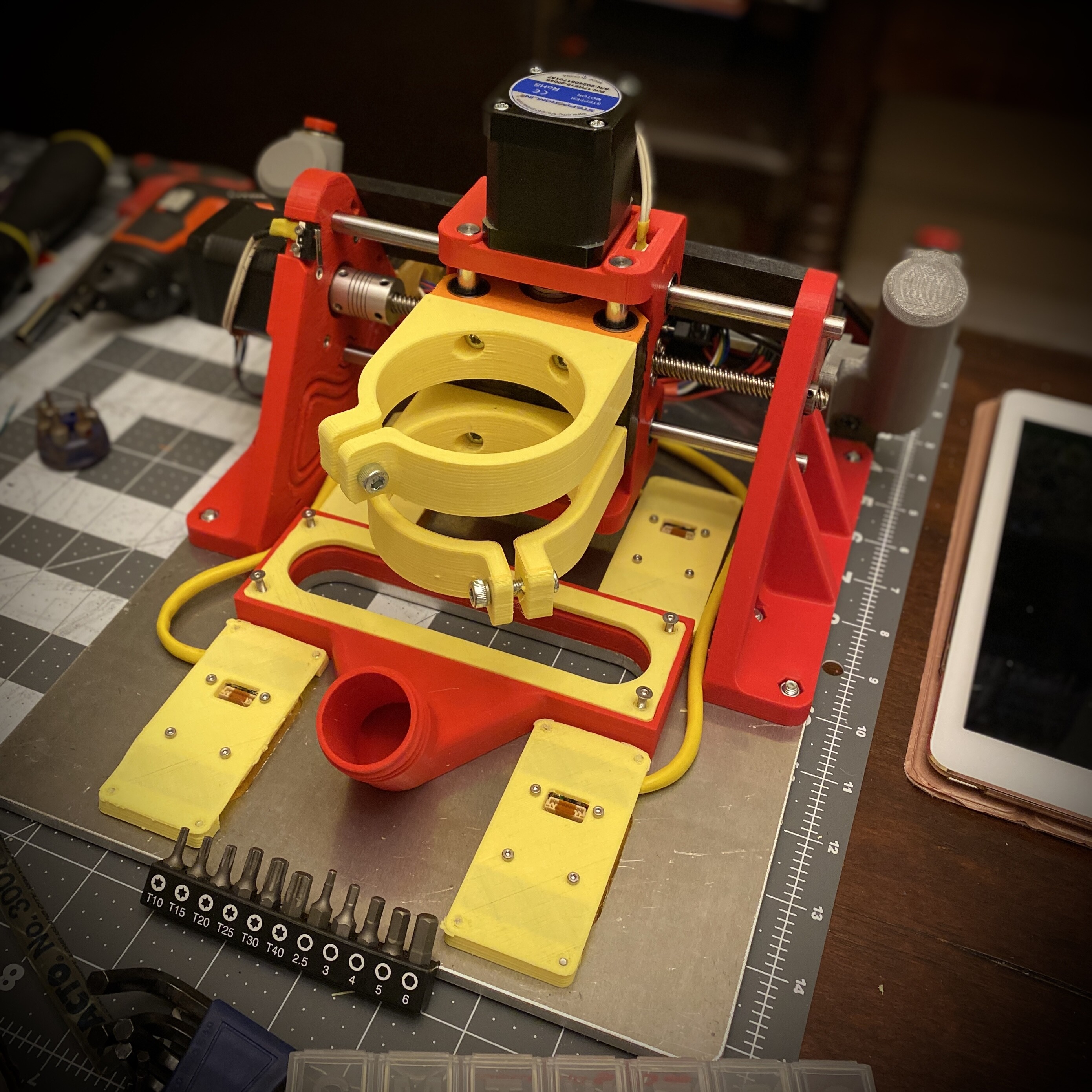
I’ve gone ahead bought a spindle and started 3D printing parts today. I dusted off my old RepRap printer and pleasantly surprised it worked without much effort… it has been collecting dust for the past few years. Nevertheless I’ve got the springMounts and sensor sleds printed tonight. And planning to print the bigger pieces at my local library.
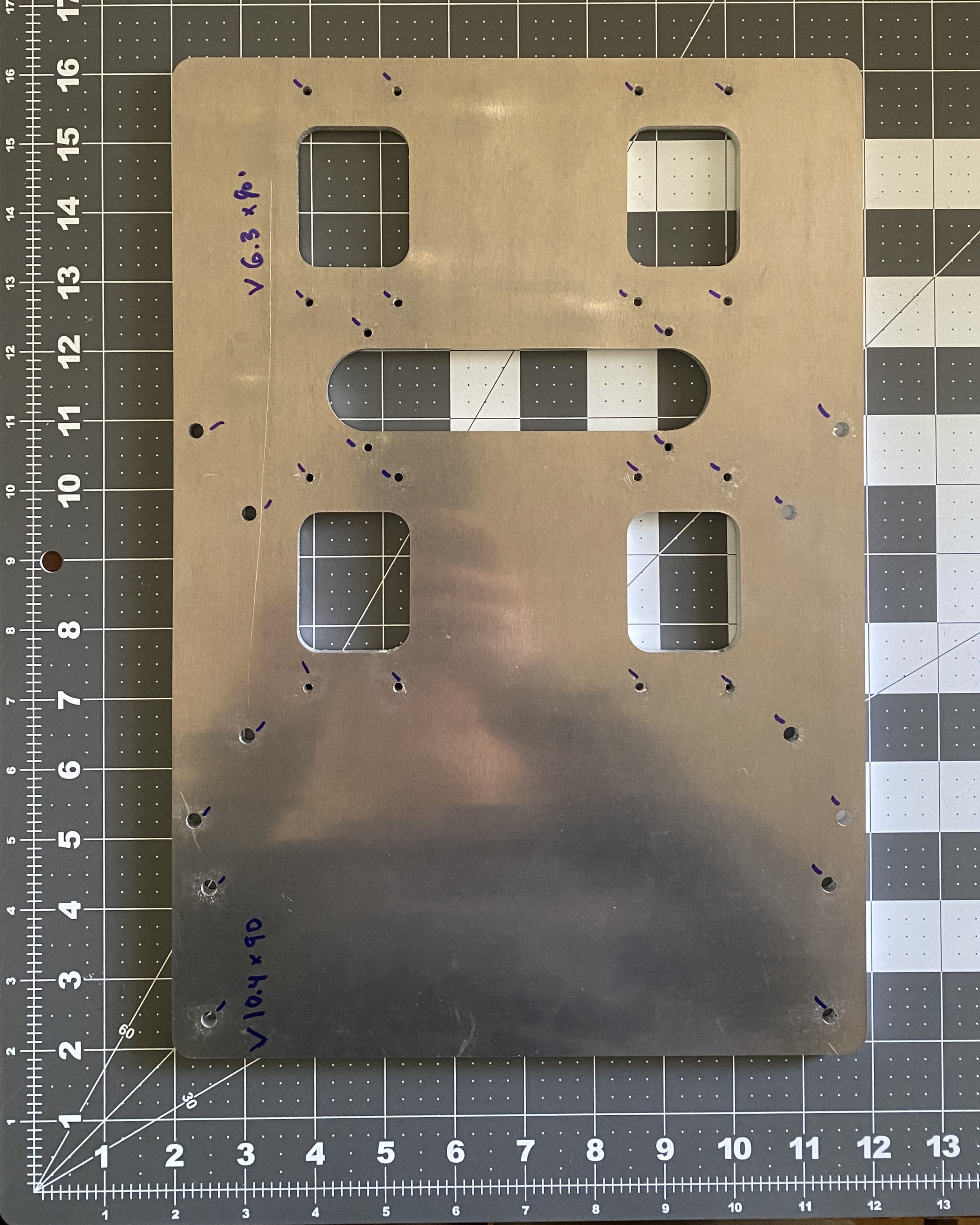
I ordered a custom fab of the baseplate from Xometry for a great price of $80 and it was cut semi-locally in the USA.
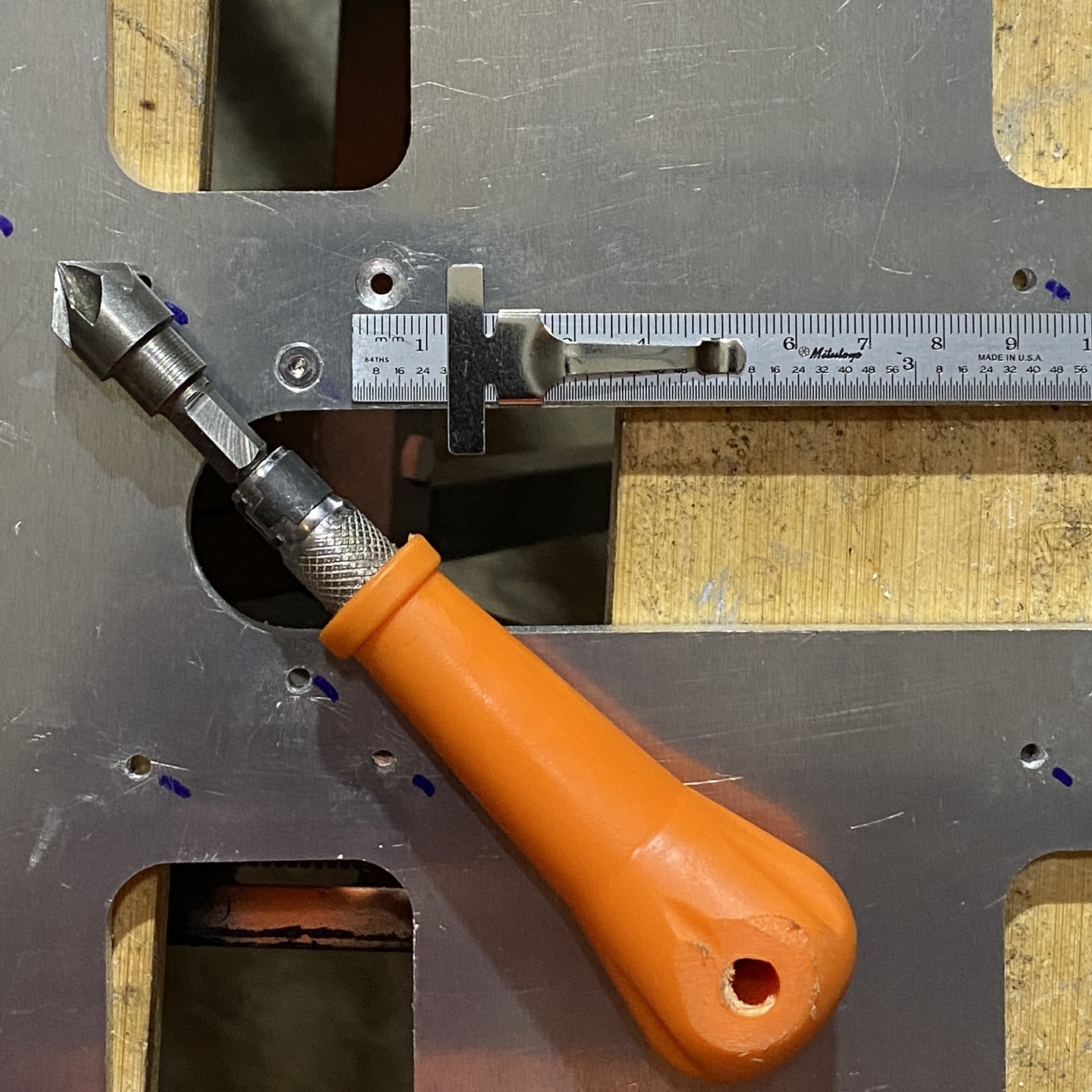
But I didn’t notice that the dxf file doesn’t include the countersink call-outs for the holes… so now I’m gonna attempt to counter sink them here at home with my hand drill and countersink bit.
Feeling a bit nervous about it, now idea how to get the needed countersink diameter other than drill a little at a time and test the fit with actual head of the screw bolt
Countersinks complete.
I took my time wasn’t too bad. Able to eyeball with the drill and just periodically clean the aluminum chip/boogers off the bit’s cutting edges. A few of them I had to finish the last couple fraction of millimeters by hand.
Thanks for the comment because it will help me stay motivated to take the time to document and share.
I’m anticipating that the build will not be too difficult for anyone that is compelled to be using a handheld router. And that individual likely has a sufficient level of carpentry skills meaning they at least understand concepts of precision and have some amount of patience and grit as personality traits
But I don’t know yet, I could be wrong…
Good stuff! I did the countersink holes for all the baseplates in the kits and went about it in a similar process. I got a drill press which I imagine probably made things quite a bit easier . Make sure that those bottom edges are nice and free of burrs too. Any burrs can prevent the machine from sliding well.
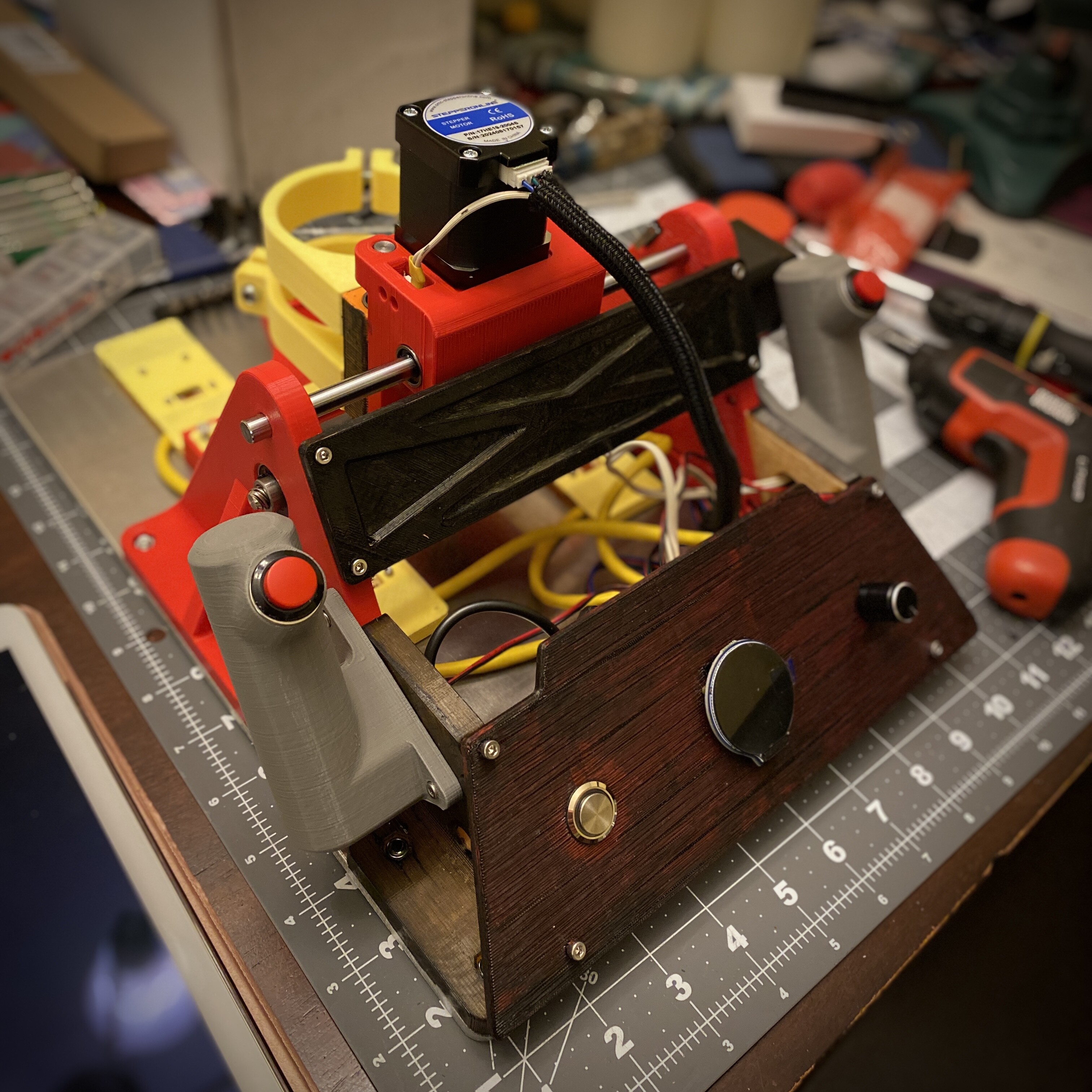
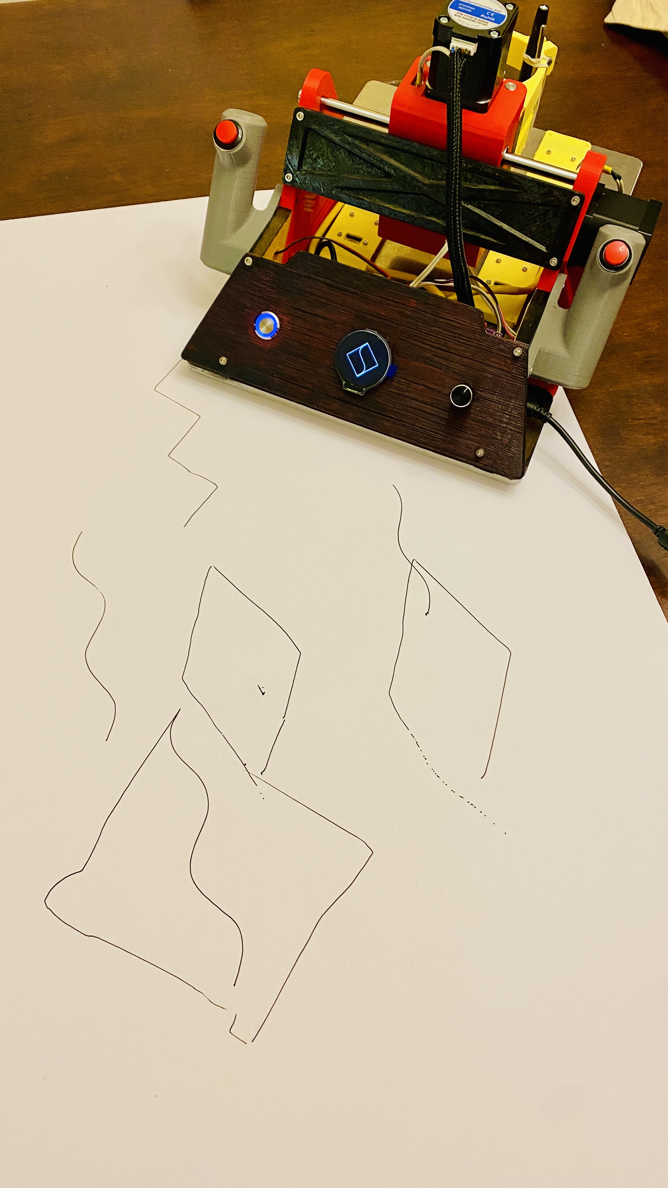
Fug Yeah! Mechanical and electrical assembly is complete.
It feels like all the screw, nut, and shaft penetrations could benefit from being about 0.5mm bigger… except for one nut penetration on the x-carriage that was a little loose and I had to macgyver some tooling to secure the nut so that I could thread the spindle mounting bracket screw.
Perhaps setting the 3D printing scale to 101-102% would help… anyone reading this may want to consider doing some test prints to test the fit of the hardware before printing everything.
I had to do a lot of reaming, shaving, and pressing to get all my hardware installed.
Also the amount of soldering is not trivial. I didn’t count but it felt like at least 150 solders maybe more. In the end my soldering skills leveled up from pretty bad to meh-marginally ok. However I haven’t fired anything up yet to confirm, other than that I was successful in setting the Vref for the stepper motor drivers.