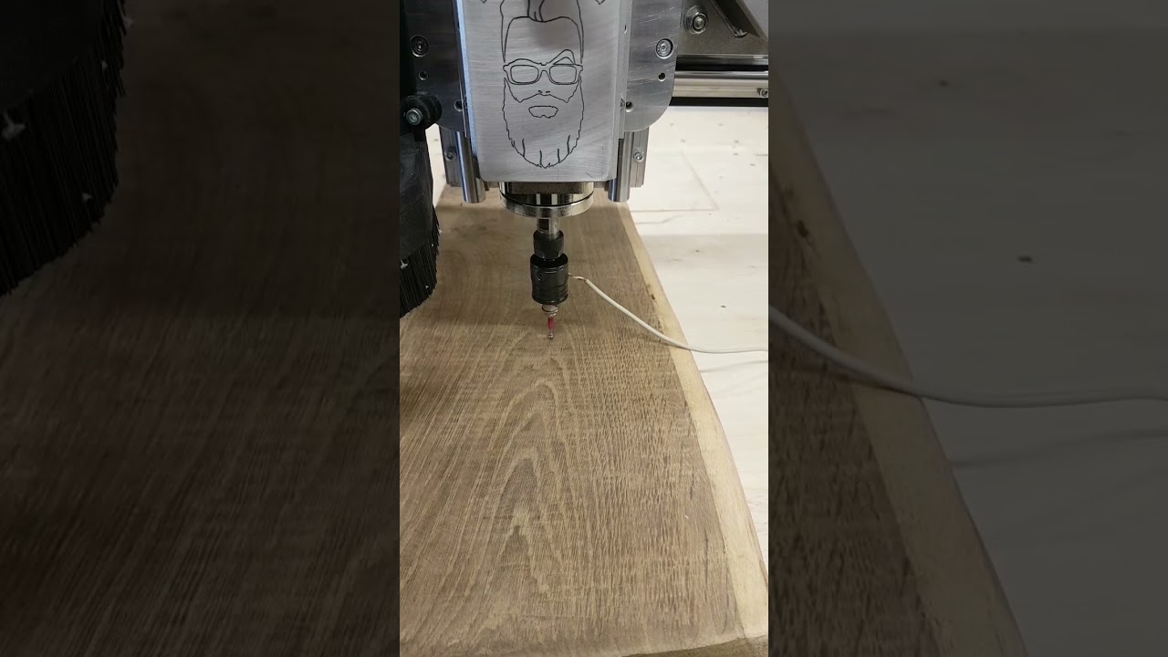
This is probably a stupid question.
But on the lowrider v3. Is it possible to do some form of bed scan where it it scans multiple points of the bed for level and/or adjusts Z0 accordingly.
I guess it would need some probe added to the gantry, but this would eliminate surfacing the bed as much(if any) and also allow for them little bit of deviations in the spoil board when placing material on top.
Just a thought, I’m sure someone would of thought of this so it maybe already answered?
If you recompile the firmware, you can add in the bed size (default, IIRC is 600mm by 600mm) and add in a mesh grid, you shoumd be able to do this. A close grid of 100mm could take a while on a full sheet bed. 1.2m by 2.4m at 100mm intervals would be 13×25 probe points, I don’t think the firmware will deal with 325 probe point mesh level. Plus, I just would not want to do it.
But make it 300mm points and then that becomes 4 by 7 which it will do just fine. I did do a 250mm mesh grid (smaller than full sheet) with mine, but different firmware. The visualization looks terrible because it’s meant for less than 0.5mm variance, and I have way more than that, but… it works.
Interesting.
Where in the firmware is this?
My bed is 3.2M by 1.5M. I wouldn’t go 100mm that would take forever. But 300mm sounds reasonable.
As I use vectric, I don’t have any visual, but could a visual be shown on the tft screen?
What level of precision are you looking for, and over how large an area? I’d probably add a known-flat filler under a workpiece and “shim” it to be parallel to Z if I needed to mount over an area where I knew the spoilboard wasn’t flat enough.
Well that’s what I’m thinking in regards to shimming.
So was thinking if a can do a bed scan that can maybe identify the points I need to shim to take a bit of the guess work out?
There are no stupid questions…
Yes, it is possible, but it isn’t trivial
Your question tells me that you need to spend a bit of time doing some research. I mean that in a nice way, just telling you that there is a lot involved, and reading articles, delving into the Marlin firmware documentation, and watching a few (or several) YouTube videos will probably be required.
Bed levelling is a fairly complicated section of the Marlin firmware, with changes to both configuration.h and configuration_adv.h files in the Marlin firmware. The changes that need to be made are a bit beyond that which can easily be described here, and once you make the required changes, then you need to compile the firmware and load it into the controller. None of those items is something that should be attempted without at least a basic understanding of what you are doing.
That isn’t to say that you couldn’t, or shouldn’t do it. Learning and messing around with the equipment is in some ways the most satisfying part of this hobby (at least that has been my experience).
This is probably something that you could easily do without having to go through the whole firmware editing process. Just set Z = 0 at the origin, and then manually move the machine (using the LCD commands or repetier-host) around your cut-able area. Slowly lower the Z axis at each point on a grid, and note the Z location at those points when the bit touches the surface (you could use a piece of paper like they do on a 3D printer to determine when the bit is close).
I’m not sure because I don’t speak German, but it appears that the first video relies on a probe.
The second video uses the touch plate and some aluminum foil, which is brilliant!
Thanks for the links!
so I was going to do this, but that relies SOLELY on using something that Estlcam controls. Like an arduino with Estlcam controller software. You cannot use anything but Estlcam controller for Contours!
Correct. ![]()
Yes, but the key you have to hit in Estlcam is the same. Just the other way round, basically, so you don’t need the aluminum foil. ![]()
I’m a bit late to the party, but wouldn’t it be just a whole lot easier to surface your spoil board instead of trying to calculate a bed leveling mesh?
Yeah, but not if you have uneven wood. ![]()
must be you do not polish it regularly, LOL
I adjusted my volume 3 times trying to understand it… then realized it wasn’t in English. its been a long day. LOL
sure if you are doing the same exact thing over and over. the scan allows for dropping the same file on any shape of surface within reason of course.

