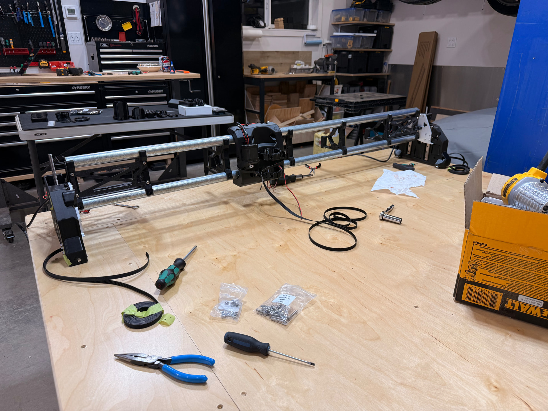
I’ve made lots of progress with my first build. I’m wondering if I’m getting binding on the (I think it’s the max) side of the assembly that rides along the Y rail.
On that side, the lead screw is more difficult to turn and the Z Stub doesn’t lower easily when I push it down. On the other hand, the opposite side lowers almost on its own, without being pushed at all.
Are both Z Stubs supposed to freely move and lower on their own without being pushed? If so, I’d appreciate some tips on what to do to get it moving freely.
What I’ve tried so far without luck:
Loosen all rail screws, move the Z Stub up and down a few times, tightened the rail screws.
Loosened the lead screw set screws and endured the lead screw is fully seated into the coupler, tightened the set screws
As I was packing up in the garage for the night, I realized I was shipped 4 Z Stubs, two of each type, and I used the ones with the slots on both sides of the assembly. So I’m planning on switching the ZStub on the max side to the other type the next time I’m in the garages working on it. Could the fact I used the wrong ZStub be causing this issue?
Usually… An unpowered, fully assembled, lubed, gantry will slowly fall under it’s own weight when the Core+Router are parked on that side.
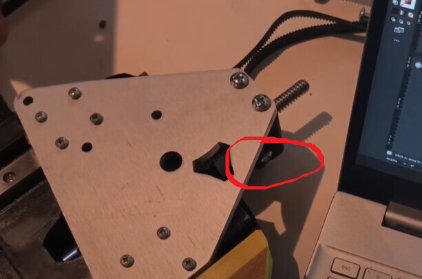
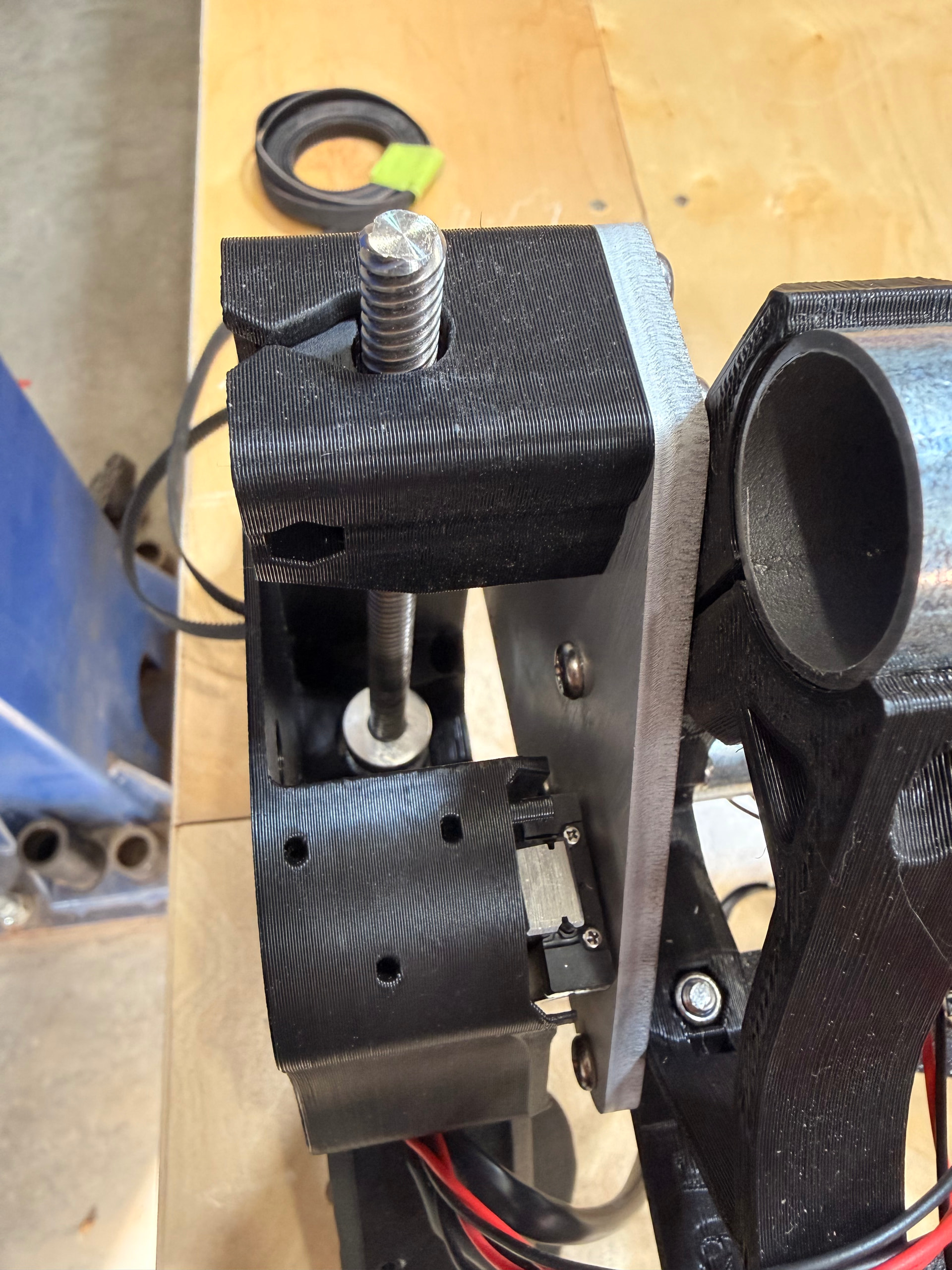
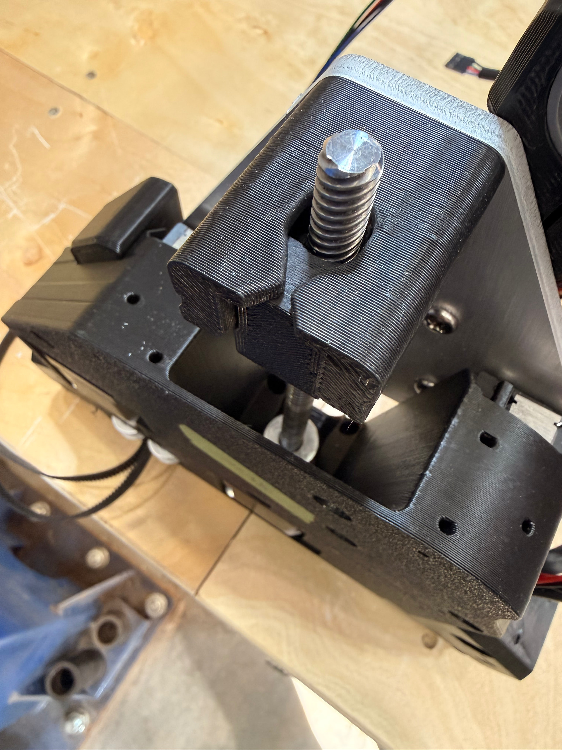
Maybe . Z-Stub for Xmax side (EMT Rail) is solid, unlike the Z-Stub for Xmin side which has a slot for the bolt secured belt.
Before Z-Stubs are attached… the sub-assembly of {YZ plates} + {Linear Rails} + {Alu XZ Plates} should be able to slide nice and freely, with absolutely no binding or resistance. XZ should glide down like a guillotine… So, watch out for what’s left of your fingers.
Below’s a 2mins vid how to check and fix if Z-nut and Z-stub are binding with each other. This info’s for people self printing parts. Since, kits from Ryan are coming off his nicely tuned/maintained printers. Am sharing in-case helps you/others…
Vaguely recall there info/tips somewhere about moving gantry low as possible before snugging up things (so that there’s minimal flexing/resistance on the connections between leadscrew, coupler and stepper shaft).
Well lit focused close up pictures might help if you’re still struggling.
If I was the one that shipped it, I apologize. I noticed after the third or so that I had some parts on two printer plates… Should not change anything though.
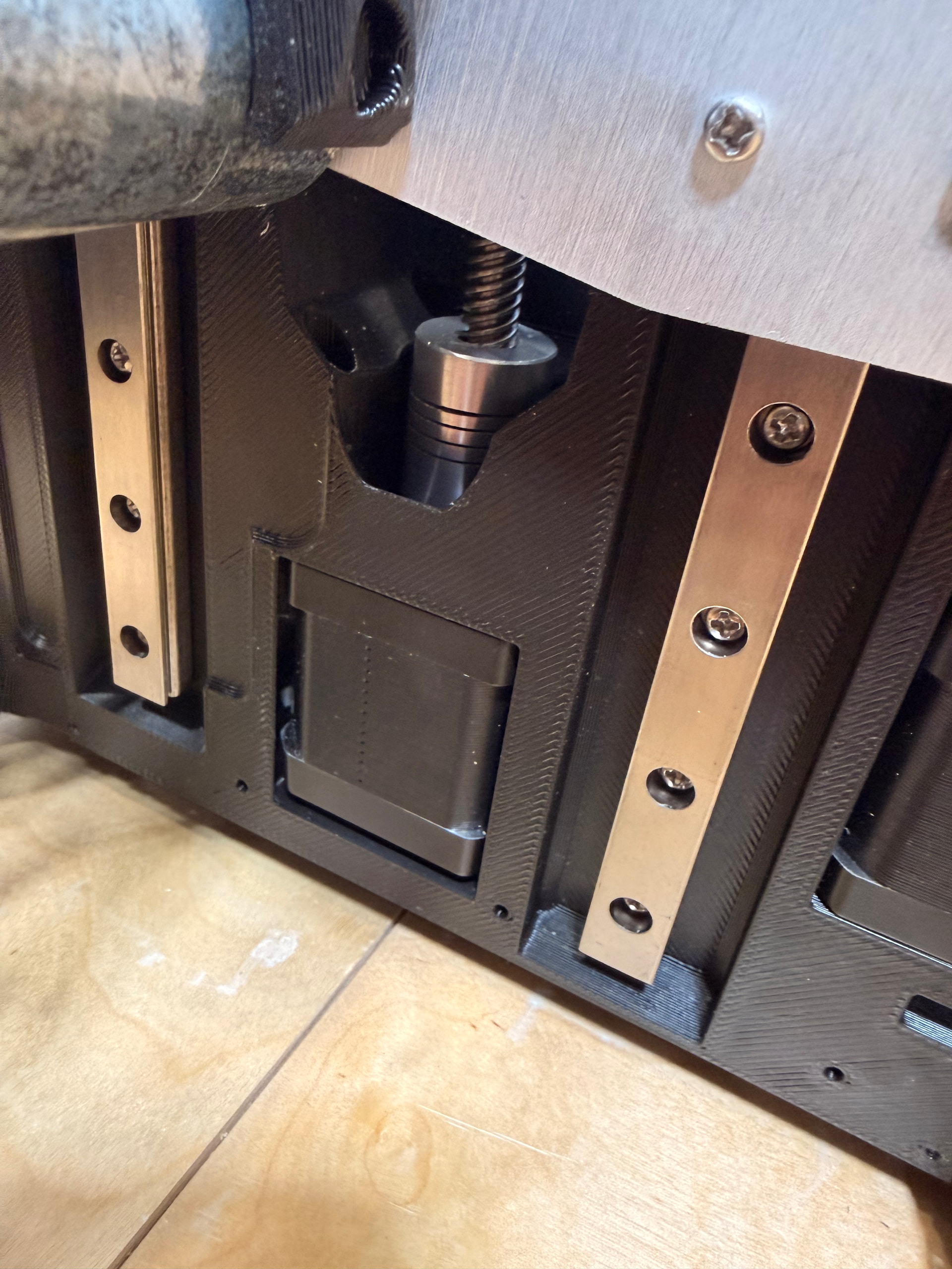
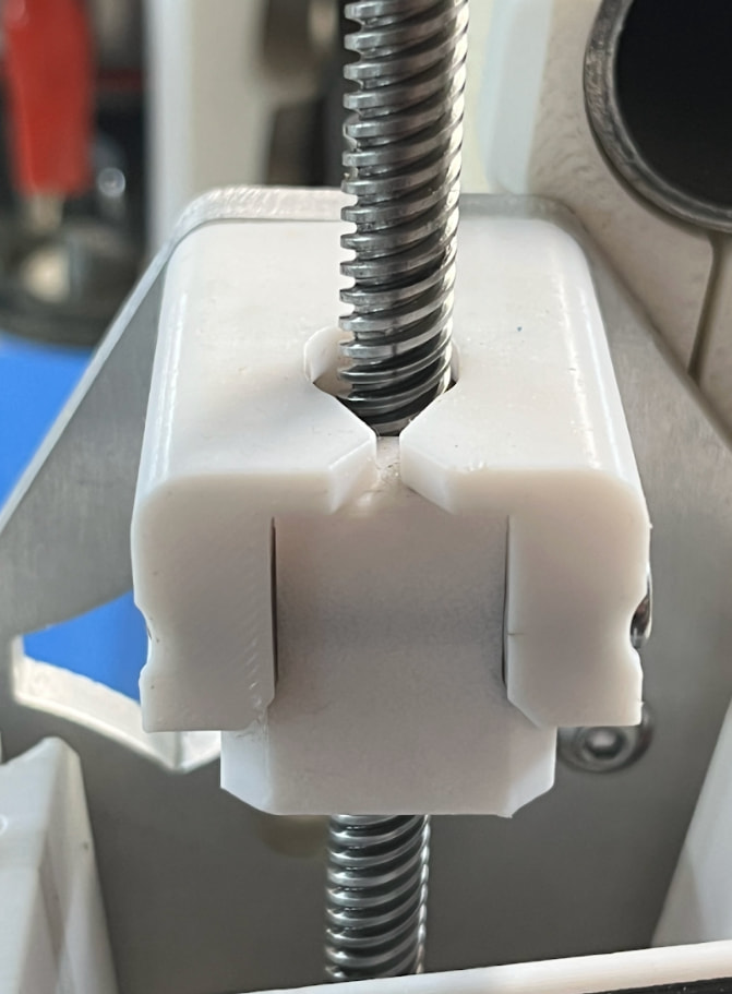
The most important things are, as mentioned before, to take the screw out (see above) and, even more important in my eyes, that the stub isn’t twisted. Loosen the two screws that connect the stub to the alu plate and rotate it a little bit so that the hole of the stub and the leadscrew are perpendicular.
Thank you all for your input. I did everything as suggested in your replies and think I’m still having difficulty with the Max side lowering on its own, is this functional as intended? Please see linked videos below:
Thank you all for your input. I did everything as suggested in your replies and think I’m still having difficulty with the Max side lowering on its own, is this functional as intended? Please see linked videos below:
Can you determine if it’s still binding based on what’s visible in the videos?
I’ve sanded the inside of the Z Stub and outside of the Z Nut, and lubed the screw with silicone grease. My next idea is to disassemble the plate, rails, and screw and reassemble from scratch.
I will try this. Hope this is my issue. Look at lead screw how it is so leaning toward the Ymax side while sitting in the Zmax stub. Hoping this is causing my Z1 binding issue because now I think I know how to solve.
He did not call it out explicitly but I can see that @rsabboud is having the same issue by looking at his pics. Z screw is shifted laterally toward one Y side or the other.
I ended up switching the nuts to the opposite side and it’s working much better now for whatever reason. I haven’t been able to finish assembly but it’s close, and if there are issues when I start using the machine I’ll order a new nut and try that.
I am still getting some binding on Z1 screw. I can get it to work by increasing motor current from 0.8A to 1.0A, but I’d rather not this be my fix since it feels like a band-aid.
I fixed the twisted stub, it’s straight as an arrow now
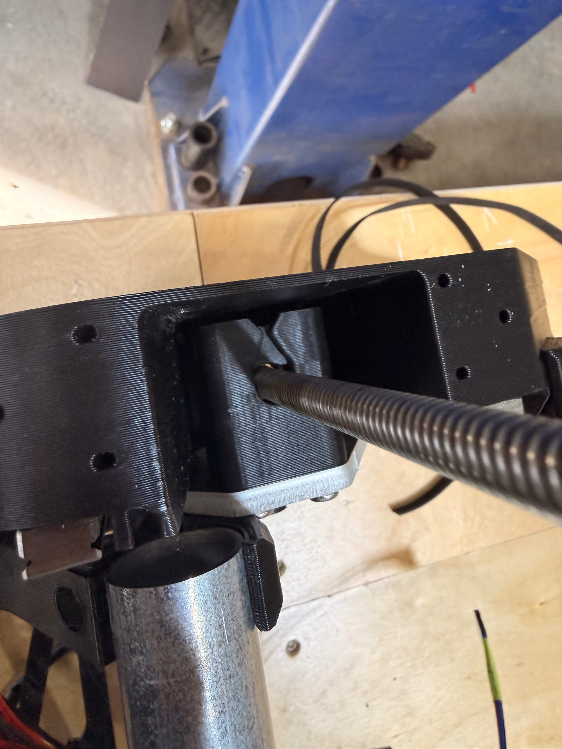
I made sure there was around 2-3mm of space between the motor shaft and z-screw when connecting via coupler
I loosened the linear rails and moved Z up and down and then retightened to make sure they are parallel with each other.
Screws are lubed up well
Next step is to just replace the dang z-screw and nut with new ones. Even though I see no damage on the screw or nut, maybe I damaged them somehow.
Are you still tracking down what’s contributing to friction/resistance?
Already checked fit of your Z nut and Z stub parts are not too tight, there’s no friction contributing to overall binding?
I don’t think perfect leadscrews are needed. For example, top of my z-axis lead screw has some wobble when rotating, but machine still lifts and drops fine because Z nut and stub are loose fit, aligned, lubed and not overly constrained.
Is binding happening more when gantry is raised, or, when gantry is low as possible? If binding is happening more at specific height(s), that may provide a clue on cause(s).
Yea thanks for your input. I actually did watch you video which causes me to print new parts on my newly calibrated Bambu P1S with 0.8mm layer height. Parts move a lot better than before but still, binding. The interface moves about as smoothly as possible lol.
It pretty consistently binds when about 0.75” (19mm) from the limit switch.
Trying to narrow it down but having a hard time.
Any issues with increasing current to motors from 0.8A to 1.0A to solve the problem?