It seems to make a ton of sense designing things like the ZenXY, MP3DP, or even the Low Rider. You start with making “blobs” for each component to define the outer bounds of each part to make sure everything fits. Then when you design the parts and make a final assembly, everything can be in the right place to begin with.
Ok that’s cool! CAD is something I very much want to get better at. But I just don’t use it enough to really get there like I would like. I do not have a mind for “designing” things like so many here do. But I still try lol.
One thing I wish they talked about a little more in the beginning was how they decided the size of the “blobs”. Do they need to be real close to the size of what you are wanting to end up with or as long as your close that’s all that matters? Stuff like that. And maybe they did and I just missed it.
It is super tough. Each project is kinda different. If a master part or sketch will work you should always use it. Sub assemblies really help things. I am still trying to work out the best way to use onshape.
In that video in particular he gets to one point and says “disregard the standard planes”. That means you have to make all new ones in relation to your part…that is a bummer. I prefer sub assemblies instead. I can’t see myself doing it the way they show, the blobs do not seem helpful to me at all. If that were me I would make each drum, with standard planes, make a drum sub assembly and use that in a master blob assembly maybe. That does force a little back and forth but seems more useful.
I am going to into the docs they reference a bit more but I am definitely not doing things the ideal way.
For my stuff it is harder as each thing has several references to the next thing.
The MP3DP I did in onshape was horrible to work with, I made it all in one document. The LR is better, I made it in separate docs, the next things will be a little better still.
His previous video he went through a bunch of design criteria for this machine, and considerations for different configurations.
In this design method, you make the space allocation in the first drawing to make sure everything has enough room. But if there is a problem you discover later, everything is dependent. So you can go back to the main drawing and change the size of those blobs. Then you have to fix any downstream problems that creates.
It seems like this stage of design is focused on finding as many problems as you can as early as you can. Those problems will be there. The earlier you find them, the “cheaper” they are to fix. He says in the beginning something about “fighting the problems instead of fighting the software”. That’s exactly why we learn new techniques like this. Finding a way to lubricate the software, so we can focus our energy on fixing problems in the design.
Wasnt he just saying that for the individual part studios with single parts? He used the faces of the part and never had to make a new plane. It was already made and inserted into the final assembly at the correct orientation he set in the first part.
Or I am missing something lol
I need to do some reading on this so I understand what you mean here.
They call the first sketch “Space Claim”. So the purpose seems to be to assign different volumes to each sub assembly or part (I mean those as common terms, not onshape terms). The benefit is that you can more easily focus on that part, or how it fits into the whole machine, and not have to work on all the parts and all their connections at once.
For something like the ZXY, I would imagine things like the corners being blobs, and having some mating interface decided in the first drawing (like the belt paths). Once you start modeling things in more detail, you might find that you need to allocate more space or flip something around in the Space Claim to make it work. In the individual Part Studios, you may need to import more than one blob to get critical dimensions figured out. You would then assemble everything at the end to make sure things work.
Where I think this method gets really tough is where you have blobs that really nest together. If you really have coupled parts, then you need to draw them at the same time. Something like the MP3DPv5 might be tricky because something like the print head is so tightly dependent on cables, rails, belts, etc.
Yeah but I use the standard planes a lot. So for a part that comes in at an angle I would have to define a new set of at least three planes. I would rather build the part as normal, and angle it later.
I guess I build things as they are going to be built, so I tend to think of things in standard machining / printing planes.
I am very interested to see if this helps him with the new design. That machine is extremely complex with a lot of artsy flowing lines and angles. It is a super hard thing to do in CAD, He almost needs to be in Blender.
I think that’s only because he made some arbitrary and weird alignment decisions with the drums. And everything stays relative to the original origin. So you can still use those planes, or import multiple blobs, and use the origin to align parts in the final assembly.
The alternative is to make a super detailed design of a drum oriented to an arbitrary origin on the drum, then assemble a ton of detailed objects together to make a final assembly, only to find out they don’t fit and you have 500 objects in your file and no way for that dependency to connect back upstream.
For me, this is how it works in my head. The master sketch can set all the variables and tolerances, not just an actual sketch. Then each parts studio has its own relevant master sketch.
So for the LR the master might be a router, work plane, as I progress I would go back in and add like the X belt position. So maybe I already do it that way I just don’t bother with the primitive shapes…I should try that. Primitive belt shape instead of a sketch point reference. That would help with the Zen or MP3DP when I refence both sides of a belt and can get lost otherwise.
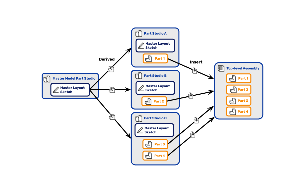
I think that’s what they are doing. He’s emphasizing that the master sketch is a “blob” or “Space Claim”, but that’s not well defined by that flow diagram.
To me, you are defining how the objects interact or line up in the first Part Studio. The “information” that document holds is that high level design. It doesn’t focus on GT6 vs GT9 or nema17 vs nem23. It doesn’t know what orientation parts are printed at.
It only enforces relationships like, there are three Z axis actuators. They are allocated this space to fit into. The motors will be in the front left/right corners. The frame is outside the mechanical parts…
Then in the individual Part Studios, you draw the pulleys and the leadscrews and how they mount to the frame.
At some point, you realize you have a problem with one of the endstops and you need more space. So you go back to the first drawing and add in that new constraint. Maybe you have to give up another constraint to make it fit. Most of the downstream parts are fine. But now you can solve the issue in the endstop part.
Assemble everything in the end and you can check fit, assembly, motion, etc.
At any rate. There’s no reason to follow any of these methods explicitly. I hope to use bits and pieces of that process in the future. But it will be adapted to my project needs.
The information flow in onshape is a bit different to any other CAD I have used. So seeing the one way flow is a new thing for me. That is a skill I can use for sure.
This way of doing things would have 100% worked when I made the CYD pendant box. The fit was so Tight I had to nudge things around a lot. This way would have been a better way.
I wonder if that is my lack of experience with CAD or my experience with software development that having that one way flow of depencencies is the only way I could think of doing it.
Another reason I probably think this is so cool is because I didn’t really know a structured way to do it before. Maybe you have better tricks already.
Well it just depends on how you link / or import them. You can have it two ways by “editing in context” or you can lock that specify way by “versioning”, you can even just use a thing as a reference as a one time reference. So you can get lost with how something is referenced or if it is even up to date. So if I make edits I do not usually version them, I make a full copy and edit the new one That way I know something is current or not or if the info is one way or two.
While I’ve used and abused Onshape pretty extensively for MPR&P V1 and V2 and other machines… I’m never sure what the final machine should look like. And my Onshape design documents always wind up a real mess… full of sketches that are not fully constrained and are often easily broken as it continues to evolve.
More typically I want to incorporate a new mechanism or drive method like R&P rather than envision what the final machine should look like. So, I usually start with the parts… i.e. rack, pinion, and mount points. And everything else then grows around it. One part then has to fit another and another… and I wind up with a Part Studio that eventually looks like a sub-assembly. Hardly “top-down” but more “bottom up”… a collection of parts that hopefully fit together. My Assembly comes last… inserting whole Part Studios and/or individual parts as necessary and joining them with mate connectors.
I try to start with parts that are strategically located around the origin and initially use the standard planes… following a similar flow to how TooTallToby speed competitions and tutorials usually go. And I always try to take advantage of symmetry where possible.
I am a long way from being an onshape expert , and having followed Martin avidly since before the first viral video, I can assure you he is eight years into learning stuff the hard way!
I doo have (cough!) quite a bit of experience in the design process however Siam happy to contribute- I will think about this and get back later when I have my computer to hand!
There is no @ one size fits all’ process, but nevertheless the principals are the same whether planning a rocket ship or a drum kit!
No, I hadn’t been drinking and it was early morning and I hate typing on my phone!
Firstly, I find it interesting that a lot of YouTube guys seem to be switching from F360 to Onshape, and that there seems to be a lot of help for them on the way.
I am happy that Martin has some super help now as he has certainly been floundering without a proper design methodology guidance. His last eight years may well have been finished in four if he’d spent three of them at design school instead of having to learn the hard way! (But we wouldn’t have had eight years of being drawn to his stuff like a bunch of moths to a flame!)
My fear is that eventually some of the really cool new features will be throttled for free users, but that is of course a digression.
The design methodology outlined is not too far from a standard analogue model except that Onshape makes it super easy to iterate changes through the various assemblies. Hence Martin’s amazement, and my own every time I have to make a change - using the outline shapes as a “tool” that do not need to be kept is a very cool trick that I only stumbled across a few projects ago.
If you can get your head around organising yourself the methodology outlined is super cool.
One key IMHO is to sort yourself out on paper before even starting - you don’t need any particular talent to do that - bubble diagrams are fine. The process is almost exactly the same as outlined above but fiddling pencil or pen on paper (or napkin) actually gives your brain a better chance to sort out the problem before the machine takes over.
Work out how the structure might work, what wiring or plumbing cables might be, think about how you want things to fit and work together. Just doodle to give you the basis for the “boxes” you need to draw, and what goes in them at a later date. Nut out the sub assemblies if you wish.
Once you have a clear idea of what it is you are trying to do. Make a new set of “bubbles” for each component on paper, see if it all fits within whatever envelope you need it to fit within, and then you have some parameters to begin your CAD outline. My “bubbles” are often fairly detailed sketches - I have books full of them - but they don’t need to be.
Having lots of sub assemblies is great if you have a monster project or there are logical breaks in the project, but don’t forget if you find you have to amend your base outline, if you derive your base sub assemblies from there - if you find something is not fitting in detail, you have to go back and alter the base which, if you have thought it through will then flow the rest of the components. That’s probably the magic sauce that takes experience more than anything, but it’s so worth it to persevere.
Sorry this is a bit of a ramble, which is kind of repeating what has already been said!
Watching design methodology in industry is fascinating.
Many things iterate as they go through product development lifecycles for a whole bunch of reasons. The end result may look very similar, almost identical, to an untrained eye while the design elements and components may have undergone radical redesign.
Things get really wild when moving between proprietary software and other alternatives.
This is really pronounced in educational environments where there is also a production capability. One may have access to educational licenses that make it easy to evaluate all kinds of tools, and yet still be locked in to a specific software ecosystem for production work.
One interesting trait that I’ve observed about some of the best designers I’ve watched is they were really good at “fiddling” around in their CAD/CAM environments and being able to really quickly respond to ‘what if’ scenarios or to wild change suggestions.
I’ve seen wild suggestions turned into a rough model and even then put through analysis tools in the span of a few hours.
I’ll bet if we query Ryan, he spends a fair amount of time just fiddling with his machine designs.
The concept of keep in and keep out areas for a machine are very common, but the amorphous blobs isn’t an approach I’d say I’ve seen employed.
That said, it’s because often times these requirements come with the delivery of a CAD model of the component or system that the design interfaces with. Instead of vague restrictions the actual mechanical interfaces can be placed directly into a design.
I’ll bet that most of the community here that post remixes do so by using the released STLs and fitting them into their own mock-up of the system, then using those to create thier parts.
That would be a fun discussion for the contributors: How do you go about creating add-ons or mods to a V1 machine?
I’m late to the party. This is going to be a bit rambley as I try to catch up on sub-threads in the thread
Blob size doesn’t matter. If you use the edges of the blobs as constraints for other parts, then if the final design of that blob is too big, you just adjust the blob and everything expands… Assuming you constrained properly and the design doesn’t hit some weird constraint that breaks everything.
A lot of my designs have done something similar, I just never knew I was doing it or had a name for it. I’ll design a lot of parts out of basic shapes. I’ll even toss in holes for where I know I want mounting points on those parts. Then I’ll design the rest of the parts that attach to the original basic shapes.
This also works really well when designing things that have to mount to stuff you didn’t design or make. Don’t bother reverse engineering the entire part. Just get the max constraints of the part and align the mounting holes in the correct spots. Electronic parts turn into big rectangles. Hoses or pipes are just cylinders (sometimes with a hole down the center if I’m feeling spicy or I need the inner diameter).
I’ve, sadly, stopped watching this particular guy. He lost me a few years back.
(this is where I start playing catchup to the rest of the thread)
I typically do sub-assembly modeling. One design will have multiple parts that all have to interact with each other. Then, I’ll link whatever part of that sub-assembly that needs to align with the next into the next one. In the end, I’ll make one final assembly where I pull all the sub-assemblies into it. The sub-assemblies are only ever linked directly to the other sub-assemblies it touches. I’m not sure if this would work with something like the MCPCNC or the MP3DP. I’ll be honest in that I haven’t tried designing something to that extent.
I’ve never used OnShape. I recently started trying FreeCAD again. FreeCAD you can link a part or even just a single sketch into another part as a sub-assembly link.
The latest version of Fusion360 seems to be forcing this one-way flow idea too. I noticed the last time I used it, you couldn’t create multiple components in the same design file anymore. They wanted everything pushed into a separate assembly file. It’s why I started looking at leaving F360. People with the ‘free’ version of f360 are going to start hitting the 10 file limit really fast if they’re working on an assembly with 11 parts and trying to work on all the components at once.
Onshape has been approaching a lot of these people with free ‘full’ access if they’ll use it in their videos. Most have even had little kick-backs if people join through their affiliate links. If onshape ever starts pulling back on what ‘free’ gets you, it’s going to start upsetting a lot of users just like F360 did.
Agreed. I still have a sketch book in the shop where I pre-design a lot of stuff. A lot of my designs never even make it into CAD unless it’s being printed.
One thing I was taught in college when designing things is to think of the design in the order of how you’d make it. That’s a little different when everything is 3d printed, but it can help there too. For instance… chamfering is always done last when making a part. When designing things in CAD, don’t do any chamfers until the very end. Chamfers like to break. Same with round-overs. Few of my parts even have those in them unless I need a fillet to help strengthen an interface. A lot of my designs are more function over form, though.